sensors Article
Easy Handling of Sensors and Actuators over TCP/IP Networks by Open Source Hardware/Software Andrés Mejías 1, *, Reyes S. Herrera 2 , Marco A. Márquez 3 , Antonio José Calderón 4 , Isaías González 4 and José Manuel Andújar 1 1 2 3 4
*
Department of Electronic, Computer Science and Automation Engineering, University of Huelva, Escuela Técnica Superior de Ingeniería, Ctra. Huelva-Palos de la Fra, 21819 Huelva, Spain;
[email protected] Department of Electrical Engineering, University of Huelva, Escuela Técnica Superior de Ingeniería, Ctra. Huelva-Palos de la Fra, 21819 Huelva, Spain;
[email protected] Control and Robotics Research Group, University of Huelva, Escuela Técnica Superior de Ingeniería, Ctra. Huelva-Palos de la Fra, 21819 Huelva, Spain;
[email protected] Department of Electrical Engineering, Electronics and Automation, University of Extremadura, Avenida de Elvas, s/n, 06006 Badajoz, Spain;
[email protected] (A.J.C.);
[email protected] (I.G.) Correspondence:
[email protected]; Tel.: +34-959-217-680
Academic Editor: Gonzalo Pajares Martinsanz Received: 14 November 2016; Accepted: 30 December 2016; Published: 5 January 2017
Abstract: There are several specific solutions for accessing sensors and actuators present in any process or system through a TCP/IP network, either local or a wide area type like the Internet. The usage of sensors and actuators of different nature and diverse interfaces (SPI, I2C, analogue, etc.) makes access to them from a network in a homogeneous and secure way more complex. A framework, including both software and hardware resources, is necessary to simplify and unify networked access to these devices. In this paper, a set of open-source software tools, specifically designed to cover the different issues concerning the access to sensors and actuators, and two proposed low-cost hardware architectures to operate with the abovementioned software tools are presented. They allow integrated and easy access to local or remote sensors and actuators. The software tools, integrated in the free authoring tool Easy Java and Javascript Simulations (EJS) solve the interaction issues between the subsystem that integrates sensors and actuators into the network, called convergence subsystem in this paper, and the Human Machine Interface (HMI)—this one designed using the intuitive graphical system of EJS—located on the user’s computer. The proposed hardware architectures and software tools are described and experimental implementations with the proposed tools are presented. Keywords: Modbus; remote access; open source hardware/software; collaborative access; EJS; Arduino; data acquisition; Internet-of-Things; HMI
1. Introduction Network-based communications allow the interconnection of sensors, actuators, control units, and computers under diverse topologies, from point-to-point connection to complex networks composed by hundreds of nodes or devices. Information transmission over a network provides important benefits in terms of reliability, reconfigurability, enhanced resource utilization, reduced wiring, and easier diagnosis and maintenance. In addition, networked communication allows taking advantage of modern data platforms and cloud-hosted services [1]. Continuous improvements in Information and Communication Technologies (ICT) are increasing the connectivity in every aspect of the modern world. A new version of the Internet Protocol (version 6, IPv6) has even been specified in order to overcome the address shortage of the traditional IPv4 addressing [2]. On the other hand, advances in sensor and communication technologies can provide
Sensors 2017, 17, 94; doi:10.3390/s17010094
www.mdpi.com/journal/sensors
Sensors 2017, 17, 94
2 of 23
the foundations for linking the physical facilities to the cyber world of Internet applications and the software world [3]. As a consequence, the concept of the Internet-of-Things (IoT) has emerged and constitutes a current promising research field. IoT deals with the interconnection of all types of embedded computing devices [4]. In other words, IoT could be described as the pervasive and global network, which provides a system for the monitoring and control of the physical world through the collection, processing and analysis of generated data by IoT devices [5]. Within this context, another dawning concept is the Cyber-Physical Systems (CPS) scenario in which machines have advanced communication capabilities. In CPS various embedded devices are networked to sense, monitor and actuate physical elements in the real world [6]. In the industry, the migration to IP for monitoring and automation is becoming increasingly popular, as Transmission Control Protocol/Internet Protocol (TCP/IP) connections offer real-time monitoring and maintenance processes, peer-to-peer communication between Remote Terminal Units (RTUs), multiple sessions, concurrency and security services [7]. In fact, in the industrial domain, the IoT is expected to bring about a fourth industrial revolution based on the industry-wide adoption of CPS [8]. By means of communication modules, TCP/IP-based solutions (hard and soft) may contribute to make remotely accessible the legacy commercial equipment that does not support Internet connectivity [1]. Concerning the adoption of IoT-based systems, in recent years, there has been a shift from systems based around the interconnection of physical components in which transmitted data has been used to facilitate control, to systems in which information is at the heart of the system and serviced by smart objects [9]. The intelligent networks of power generation and distribution, called Smart Grids (SGs) constitute another modern research arena where TCP/IP networks are applied. SGs are also inside the CPS concept since they are a special example of a cyber-physical infrastructure [10]. A particular case of application of networked communications that has attracted a lot of attention during last years is engineering education. From the point of view of engineering education, small/lab scale plants, that have a similar operation in their fundamental aspects to plants or industrial systems, constitute an essential tool for students to acquire skills for their professional future [11,12]. In many cases, these educational plants contain sensors and actuators similar to those that can be found in most of the common industrial systems. Besides, they cover many fields in engineering, such as building management, electrical power, renewable energies, electronics, electrical machines, hydraulics, etc. Some examples of these products can be seen at [13–15]. Access to these educational plants can be carried out basically in two ways: locally and remotely. Local access assumes that the user attends in person lab classes where can program and/or configure these plants. Several limitations arise when they are used in this way: the number of plants is reduced because of their high cost, and some plants can mean dangerous to the student if they are improperly operated, such as motors and generators of some power. Time availability of educators is also an aspect to be taken into account. Conversely, remote access is emerging as one of the most important trends in the use of laboratories [16–19]. This kind of access may improve some shortcomings of local access, such as safety aspect of users and the possibility that plants can be used 24 h a day, without being limited to the university schedule. However, access to these plants constitutes a major technological challenge, due to the many aspects that need to be addressed (communications, design of user interfaces, access to different sensors, performing actions on the actuators, communications security, etc.). Various works perform in-depth reviews of virtual and remote labs in engineering education emphasizing the benefits of their use [18,20–22]. Particularly for control education, a recent survey is reported in [19]. Regardless of the context, IoT, CPS, etc., the handling of sensors and actuators and, hence, the associated data is performed over TCP/IP networks. This kind of communication needs special attention from the scientific community to resolve some pending challenges among which remote access [7]. Nowadays, there are several specific solutions to access different kinds of sensors and actuators through a TCP/IP network, either local (Local Area Network, LAN) or wide area type (Wide Area Network, WAN). The usage of sensors and actuators with different interfaces (SPI, I2C,
Sensors 2017, 17, 94
3 of 23
analogue, digital, serial . . . ) make the access to them from a network in a homogeneous way more complicated. If secure access to these devices is required (by encrypting communications), the design of the entire system becomes more and more complex. Taking into account these requirements, a framework, including both software and hardware resources, is necessary to simplify and unify networked access of diverse sensors and actuators. Such a framework constitutes a tool that would greatly simplify the design of management systems, monitoring interfaces, alarm systems, etc. One of the main problems that often arise when implementing remote access to a system (usually including actions on actuators, implementation of control strategies, design of sensors monitoring systems, etc.) is the lack of software and hardware tools to approach the design of the whole scenario that is necessary to fulfill. Moreover, in many cases, only commercial software tools are available, which means an expense that is unaffordable in several applications. In the literature we can find many examples of access to remote systems where implementation is performed using commercial software, ad hoc designs or a mixture of both solutions [23–33]. In this regard, in the path towards the future generation of technological processes, there is a trend to replace proprietary approaches with open and standardized solutions [34]. In this sense, Botta et al. [35] assert that research efforts must be done in the direction of defining standard protocols, libraries, languages, and methodologies for enabling the full potential of IoT. Open source platforms are a viable alternative to commercial packages. The first ones offer benefits like more control over the system and data, more low-level configurability to the developer, and the collected data does not have to reside on third party databases [1]. Easy Java/Javascript Simulations (EJS) [36] is an open-source tool created by Esquembre [37] to build discrete simulations. Based on Java, this software provides an environment for rapid development of interactive virtual laboratories. In addition, EJS also allows designing remote laboratories thanks to the continuously released extensions that enable connection with software and hardware entities. In fact, it has been broadly used to construct such educational resources for universities all around the world. Some examples for engineering education cover several scopes like automatic control [29,30,38,39], robotics [25,40], automation [26,33], photovoltaic systems [41], supervisory systems [42]. Regarding the extensions, EJS can connect with external software widely used in academic and research laboratories, namely Java-Internet-LabVIEW (JIL) [43] and Java-Internet-Matlab (JIM) [44]. Some other tools recently released are related to robotics [40], augmented reality [45], integration and booking in Moodle [46,47], collaborative support [48], Reader Apps for Android and iOS [21], use of Javascript [49]. An emerging trend within this scope is the use of low-cost and open-source platforms such as Arduino [50], Phidget [51] or Raspberry Pi [52]. These devices provide easy-to-use hardware and software environments to develop different implementations in the fields of data acquisition, automation and engineering in general. Open-source code is a critical benefit. This feature implies that there is an increasing amount of shared information available all around the world about academic, scientific and non-professional projects. Some examples of recent applications based on these devices are now discussed. Real-time monitoring of fuel cells using LabVIEW [53] and Arduino is reported in [54,55]. Applications in solar energy facilities are presented in [56,57]. Developments related to IoT are described in [58,59]. Utilization to control in robotic applications can be found in [60] (humanoid robot) and [61] (mobile robot). They are also used for data transmission through ZigBee protocol building Wireless Sensor Networks (WSNs) [62–67]. For educational purposes, in recent years some approaches have taken advantage of these platforms. For instance, a hardware-in-the-loop scheme with educational orientation is proposed in [68]. Within the remotely accessible labs, integration of EJS with Raspberry Pi and Arduino is reported in [69–71]. As it has been previously mentioned, networked sensors and actuators is an active field of research concerning issues related to security [7], smart devices development [66,72], data storage and processing [35,73], architectures [74–77], software applications [58]. A noteworthy research trend is the standardization of interfaces for smart network transducers according to the IEEE 1451.0 standard [78]. This protocol aims at simplifying the connectivity of smart sensors and actuators to the communication networks. Namely, it has proven to be a useful framework to develop remote educational labs [79–82].
Sensors 2017, 17, 94
4 of 23
This paper presents a set of open-source software tools, specifically designed to cover the different issues concerning the access to sensors and actuators, which have been integrated in the authoring tool EJS. Furthermore, low-cost hardware architectures are proposed to operate with the abovementioned software tools allowing an integrated and easy access to local or remote sensors and actuators. Likewise, real application cases entirely developed with these tools, without use of commercial software, are presented. The outline of the remainder of the paper is as follows: Section 2 gives an overview of the main features of the system. Section 3 deals with the proposal of hardware architectures and software approach for the convergence subsystem. In Section 4, a solution for unifying the communications is highlighted. Demonstrative results are presented in Section 5. Finally, the main conclusions of the work and future guidelines are addressed in Section 6. 2. System Overview The design of a complete system that controls a process (plant) from the network should include two main parts or subsystems. On the one hand, a subsystem which allows sensors and actuators to be accessed from a remote network location. This subsystem must integrate sensors and actuators into the network, usually using the TCP/IP protocol, and is called convergence subsystem in this paper. The convergence subsystem is also a requirement to make accessible any other device—like cameras, measurement equipment, control system, etc.—of the remote plant from the network. On the other hand, in order to make the plant accessible from the network, a Human-Machine Interface (HMI) that allows the interaction between the user and the process is necessary. This interaction is carried out through the corresponding control elements available on the HMI. It also allows the user to track the process evolution through the corresponding flow of information (video streams, parameter evolution graphics, position of an actuator, etc.). The HMI, running on the user’s computer—PC, tablet, etc.—must have network access. Some of the requirements imposed on every HMI for proper working are: rich and informative visual resources, a high level of interactivity, easy-to-use, friendly and intuitive user interface, flexibility to accept changes and so on. Also, there are various desirable features such as connectivity with other software packages, rapid design, low computational requirements and easy management of data. Therefore, the HMI and the convergence subsystem have to be implemented to achieve the remote use of a plant of any type—experimental, development or research plant. Figure 1 shows the complete diagram that integrates the convergence subsystem, the HMI and the rest of the parts involved in a remote access to a plant. Sensors 2017, 17, 94 5 of 21
Figure 1. 1. Simplified Simplified block block diagram diagram of of aa remotely remotely accessed accessed plant. plant. Figure
However, the aforementioned commercial packages do not provide a general methodology for developing the convergence subsystem and a great economic effort is required to use them to make a process accessible from the network. As an alternative to LabVIEW and MATLAB/Simulink, there is an interesting free authoring tool called Easy Java/Javascript Simulations (EJS). Its validity for implementing user interfaces has
Sensors 2017, 17, 94
5 of 23
In addition to proprietary solutions provided by the manufacturers of some of the devices in a plant sensors, valves, motors, measurements devices, etc., there are other solutions that enable the integration in a network of any of these devices. Indeed, there are different applications to develop the convergence subsystem and the HMI. Among the most used in the scientific field (both educational and research-development), LabVIEW and MATLAB/Simulink [83] are very common. LabVIEW provides particular solutions to develop convergence subsystems for processes of any nature (electric, electronics, hydraulic, energy, etc.). MALTLAB/Simulink also offers hardware support for receiving and sending data directly from MATLAB/Simulink to lab instruments, data acquisition systems, image and video acquisition modules. Both products, LabVIEW and MATLAB/Simulink, are suitable to implement the HMI and the convergence subsystem in any type of process. Another option relies on developing the HMI using general purpose languages like Java, C, Python, etc. This case requires advanced expertise and programming skills for designing the communication interfaces with devices, data formatting and transmission, and visualization. These factors may constitute an extra effort when the purpose is to develop and deploy the networked system in a rapid and effective manner. However, the aforementioned commercial packages do not provide a general methodology for developing the convergence subsystem and a great economic effort is required to use them to make a process accessible from the network. As an alternative to LabVIEW and MATLAB/Simulink, there is an interesting free authoring tool called Easy Java/Javascript Simulations (EJS). Its validity for implementing user interfaces has been widely contrasted with processes of different nature in the educational field. In fact, EJS successfully fulfills the above mentioned HMI requirements. However, EJS has not been used to implement convergence subsystems so far, since it did not include the necessary tools to connect with hardware devices. Thus, until now, the access to hardware devices from EJS was done using connections to applications such as those mentioned above. For example, in [29] the authors shows the design of a remote plant using MATLAB, LabVIEW and EJS. In [44] a networked control lab is designed using EJS and MATLAB/Simulink. A fuzzy controller is applied by a Programmable Logic Controller (PLC) using EJS to implement the remote HMI whereas a LabVIEW application communicates such interface with the PLC via Object-Linking and Embedding for Process Control (OPC) in [33]. To provide EJS with the ability to connect directly to hardware devices, this paper presents a set of software tools, called elements. All of them are integrated in EJS. These elements provide EJS the functionality of developing convergence subsystems in a simple way, dragging and dropping them using the EJS environment, Figure 2. In addition, they solve the interaction issues between the devices connected to the convergence subsystem and the HMI—this one designed using the intuitive graphical system of EJS. All these elements are based on open software and low cost hardware platforms, and are designed by developers from different origins (universities, non-professional people) according to the open source philosophy.
connections to applications such as those mentioned above. For example, in [29] the authors shows the design of a remote plant using MATLAB, LabVIEW and EJS. In [44] a networked control lab is designed using EJS and MATLAB/Simulink. A fuzzy controller is applied by a Programmable Logic Controller (PLC) using EJS to implement the remote HMI whereas a LabVIEW application communicates Sensors 2017, 17, 94 such interface with the PLC via Object-Linking and Embedding for Process Control 6 of 23 (OPC) in [33].
Figure 2. Some elements developed for EJS to access hardware platforms. Figure 2. Some elements developed for EJS to access hardware platforms.
3. The Convergence Subsystem In this section, two different architectures are presented to design the hardware of the convergence 7 of 21 subsystem. They are general architectures, depending on the complexity of the device/plant that requires being accessible from included a network. The overall system is presented in Finally, Figure 3,inwhich will Both architectures have been in Figure 3 (framed with black lines). Section 3.4 explained from now on. the software developed to implement the convergence subsystem is presented. Sensors 2017, 17, 94
Figure 3. General diagram proposed to implement the convergence subsystem. Figure 3. General diagram proposed to implement the convergence subsystem.
3.1. Layer of Level Adaptation With respect to the plant and taken into account that it can include devices with very different This out the as voltage range adaptation plant inputs/outputs and the data nature, thelayer plantcarries is considered a black box with a set ofbetween n input variables and m output variables, acquisition layer. Regarding digital signals, the logic levels of actuators and sensors could be different from those of the data acquisition layer. Therefore, the ranges must be adapted to appropriate levels (for example from 0/3.3 V to 0/5 V or vice versa). Bidirectional low cost devices are included to perform this adaptation. In the case of analog signals, their adaptation to the most commonly used digital levels in A/D devices (0/3.3 V or 0/5 V) is necessary.
Sensors 2017, 17, 94
7 of 23
as can be seen at the bottom of Figure 3. The outputs are signals coming from sensors located in the plant to monitor the evolution of the process or the behavior of the plant. The inputs are signals applied to the actuators coming from a controller. Before developing the complete convergence subsystem, the different functional layers must be established. They are required to access the plant from any TCP/IP network. The necessary layers of the proposed convergence subsystem are (top of Figure 3):
• •
•
•
The network interface, that is, the layer that provides access to a TCP/IP network. The layer of data processing/computing. It provides: TPC/IP protocol, the capability of processing to allow the establishment of network communications, and the capability of data computing. This layer also establishes the indispensable safety actions. An example of a safety action is to prevent overspeeding of an electric machine or its overheating. The data acquisition layer. This one provides the interface which allows the layer of data processing/computing to receive and send the information required for following the process evolution. In fact, input and output signals should be adapted according to the characteristics of the Data Acquisition System (DAQ), which should enable the processing of signals with the most common values. In addition, the DAQ usually allows digital inputs and outputs buses, such as RS232, I2C, SPI and DALLAS, among others. Finally, the layer of level adaptation has been introduced. Indeed, the digital and analog outputs to be processed from the plant by the DAQ need to be properly conditioned—amplification, filtering, linearization, optocoupling. This is the mission of this layer.
This structure, combined with the software tools that have been designed, has the following characteristics:
• • • •
Generality. It consists of using components with scalability and modularity. Thus, the proposed solution is adapted to plants with different data processing needs. Economic viability. It consists of using open hardware platforms and open source software. Easy design. The designer does not have to be trained on advanced knowledge in communications and electronics neither programming expertise. Rapid development and deployment. Due to the previous features, the time devoted to develop and implement the convergence subsystem is reduced.
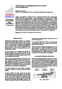
The rest of this section is organized as follows: in Section 3.1 the layer of level adaptation is developed. This layer is common to both architectures proposed in this paper. The first one has been developed for processes with low complexity. It is presented in Section 3.2. The second architecture has been developed for processes with medium/high complexity and it is presented in Section 3.3. Both architectures have been included in Figure 3 (framed with black lines). Finally, in Section 3.4 the software developed to implement the convergence subsystem is presented. 3.1. Layer of Level Adaptation This layer carries out the voltage range adaptation between plant inputs/outputs and the data acquisition layer. Regarding digital signals, the logic levels of actuators and sensors could be different from those of the data acquisition layer. Therefore, the ranges must be adapted to appropriate levels (for example from 0/3.3 V to 0/5 V or vice versa). Bidirectional low cost devices are included to perform this adaptation. In the case of analog signals, their adaptation to the most commonly used digital levels in A/D devices (0/3.3 V or 0/5 V) is necessary. To carry out this levels adaptation (mapping), the designed adapter is shown in Figure 4 (Mapping Circuit of Level Adaptation Layer, MCLAL). This circuit, besides mapping voltages, converts currents to voltages. For example, the mapping of signals 4/20 mA to 0.4/2 V or 0/20 mA to 0/2 V is possible only closing the jumper JP3. Furthermore, this circuit has two advantages over the commercial devices
included to perform this adaptation. In the case of analog signals, their adaptation to the most commonly used digital levels in A/D devices (0/3.3 V or 0/5 V) is necessary. To carry out this levels adaptation (mapping), the designed adapter is shown in Figure 4 (Mapping Circuit of Level Adaptation Layer, MCLAL). This circuit, besides mapping voltages, converts currents to voltages. For example, the mapping of signals 4/20 mA to 0.4/2 V or 0/20 mA to Sensors 2017, 17, 94 8 of 23 0/2 V is possible only closing the jumper JP3. Furthermore, this circuit has two advantages over the commercial devices most commonly used for this purpose. Firstly, it is only fed with 5 V versus symmetric powerused supply needed by many of the independent setting for most commonly for this purpose. Firstly, it isother. only Secondly, fed with 5 itVhas versus symmetricgain power supply each channel. needed by many of the other. Secondly, it has independent gain setting for each channel.
Sensors 2017, 17, 94
Figure 4. 4. MCLAL MCLAL circuit circuit from from 0/3.3 0/3.3 V Figure V to to 0/5 0/5V. V.
8 of 21
The layer layerofoflevel level adaptation should the output from the D/A converters The adaptation should alsoalso mapmap the output signalssignals from the D/A converters located located at the input of the plant. The actuators usually need voltages at the input of 0/10 V or −10/10 at the input of the plant. The actuators usually need voltages at the input of 0/10 V or −10/10 V. V. The output voltages the converters D/A converters are usually V V. orTo 0/5 V. To out this The output voltages fromfrom the D/A are usually 0/3.3 V0/3.3 or 0/5 carry outcarry this mapping, a been circuit has beenFigure designed, Figure This circuit includes, the single previous one,supply single amapping, circuit has designed, 5. This circuit5.includes, as the previousasone, voltage voltage supply and independent setting (forR10, negative values R10, R11 or R8 fordepending positive values, and independent setting (for negative values and R11 or R8 forand positive values, on the depending on the position of jumpers JP1 and JP2). Figure 6 shows a prototype of athis circuit position of jumpers JP1 and JP2). Figure 6 shows a prototype of this circuit realized with perfboard realized with a perfboard (DOT PCB). (DOT PCB).
Figure5.5.MCLAL MCLALcircuit circuitfrom from0/10 0/10VVto to− −10/10 Figure 10/10VVor, or,in ingeneral, general, to to –V/+V. –V/+V.
Once the implementation of this layer has been solved, the next step is to deploy the remaining three layers (network interface, data processing/computing and data acquisition). Next two sections deal with the implementation of these layers for low complexity and medium/high complexity processes.
Figure 6. Prototype of the MCLAL circuit of Figure 5.
Sensors 2017, 17, 94
9 of 23
Figure 5. MCLAL circuit from 0/10 V to −10/10 V or, in general, to –V/+V.
Figure 6. Prototype of the MCLAL circuit of Figure 5. Figure 6. Prototype of the MCLAL circuit of Figure 5.
Once the implementation of this layer has been solved, the next step is to deploy the remaining 3.2. Architecture for Processes with Low Complexity three layers (network interface, data processing/computing and data acquisition). Next two sections low complexity need layers simplefor actions the convergence subsystem, for example, deal Processes with the with implementation of these low of complexity and medium/high complexity to turn the process on or to impose a certain voltage level in response to a signal generated by the processes. user. In all these cases, the need of data processing is low. Thus, the corresponding algorithm is very 3.2. Architecture Processes with Low Complexity simple. Also, thefor process security is frequently very easy to implement. Therefore a single component is proposed to complete the architecture of the remaining three layers of the convergence subsystem: Processes with low complexity need simple actions of the convergence subsystem, for example, a development board based on low cost microcontrollers (as can be seen at the top in the middle of to turn the process on or to impose a certain voltage level in response to a signal generated by the Figure 3). These devices have digital inputs and outputs, analog inputs and outputs and digital serial user. In all these cases, the need of data processing is low. Thus, the corresponding algorithm is very communication buses, as well as processing power and network interfaces. simple. Also, the process security is frequently very easy to implement. Therefore a single The development board chosen for this first architecture, among many others available in the component is proposed to complete the architecture of the remaining three layers of the convergence market, is the free Arduino hardware platform. In recent years, Arduino has become one of the most subsystem: a development board based on low cost microcontrollers (as can be seen at the top in the commonly used platforms. In terms of technical specifications, Arduino development boards provide analog inputs and digital outputs. Depending on the model, the voltage ranges are 0/5 V or 0/3.3 V. They also have available serial buses with I2C, SPI and RS232 protocols. There are also cards with an Ethernet interface. The extension modules (shields) can be plugged on top of the Arduino extending its capabilities (Ethernet interface, motor control, GPS, etc.). Arduino boards also have a large number of libraries that allow the implementation of the TCP/IP protocol and the functions of data acquisition and processing in an easy way. All these characteristics of Arduino boards make them suitable for developing the layers of data acquisition, data processing/computing and the network interface. Thus, the proposed architecture consists of an Arduino Ethernet board or a Mega board with an Ethernet shield. This architecture is an easy and cheap (under $50) solution for cases in which the need for data processing is low. 3.3. Architecture for Processes with Medium/High Complexity Arduino boards allow the development of complex software. However, they neither support a high number of concurrent accesses from the network nor massive data storage/processing. Therefore, in the case of applications with these requirements, an alternative architecture is proposed for the implementation of the remaining three layers of the convergence subsystem. In this alternative architecture, an embedded operating system has been included to manage the data storage and to increase the number of concurrent accesses from the network. In addition, it allows the use of fast development tools to design the applications needed to control the plant. This operating system must meet the characteristics listed above for the general solution. Therefore,
Sensors 2017, 17, 94
10 of 23
the use of Linux, the free operating system most widely used, is proposed. The next step is to choose a hardware platform for Linux and to develop the remaining layers of the convergence subsystem. The use of i86 and ARM based boards is proposed for this kind of processes (at the top in the right of Figure 3). The main advantages of these architectures versus others existing in the market are their adaptability and scalability. They are also the most commonly used in industrial applications. The i86 family (32 and 64 bits) has a large number of motherboards with different form factors, as for example Mini-ITX (17 × 17 cm), Nano-ITX (12 × 12 cm), Pico-ITX (10 × 7.2 cm), NUC (10 × 10 cm), etc. and a wide range of processing capabilities. From 32-bit processors up to 64 bits multi-core processors can be used, like the Intel Atom, i3, i5 and i7 processors. In the same way, there is a high number of motherboards for the ARM processor and for industrial uses with the same form factors as the i86 boards. They can also be used to implement this second architecture. In addition, there are boards based on this processor with reduced sizes and prices, such as PhidgetSBC3 and Raspberry Pi. These boards are capable of running embedded Linux operating system and they are an intermediate solution between Arduino-based and i86/ARM boards. All the mentioned boards have a network interface and at least one USB port. With that, all of them are suitable for developing the layers of network interface and data processing/computing. Moreover, the layer of data acquisition must be implemented to complete the structure of the convergence subsystem. There are low cost data acquisition boards connected by USB which can be used to implement the data acquisition layer. Among all the possibilities, Phidget boards have been chosen. Several elements developed for EJS provide access to different USB cards from Phidget. This manufacturer offers a wide range of drivers for Windows, Linux and OS X operating systems for all its products. It also offers libraries for developing applications in any programming language (including Java). This last feature constitutes an advantage versus other alternatives. Phidget also provides acquisition boards with digital I/O and analog inputs, boards with digital outputs −10/10 V, PWM outputs, etc. These boards can be connected to any architecture based on i86 or ARM processors running Linux operating system. The complete system provides the processing capability necessary in the process, and allows the implementation of the data acquisition layer of the convergence subsystem. In addition, Phidget also offers a board, PhidgetSBC3 [84], based on an ARM processor with embedded Linux, which incorporates an interface with eight digital inputs, eight digital outputs, eight analog inputs and six USB ports, to which any other board needed to develop the complete structure of the convergence subsystem can be connected. Arduino boards can be also connected to an USB port for data acquisition. To do this, the Arduino board must be programmed with the Firmata sketch, available in the integrated development environment (IDE) of Arduino. This sketch allows the communication between the computer that implements the layer of data processing/computing and the Arduino board. An element developed for EJS (see Figure 2) provides complete access to Arduino boards connected to an USB port of an i86/ARM board. 3.4. Software of the Convergence Subsystem Once analyzed the different configurations of the hardware architecture, in this subsection the software to develop and implement the convergence subsystem is shown. Besides the primary functions mentioned beforehand, the convergence subsystem must also implement the three next functions:
• • •
Communications between the convergence subsystem and the user interface. Control of the process behavior. Process safety.
The first function is responsible for the exchange of information between the user interface and the convergence subsystem. The function to control the evolution of the process is in charge of processing
Sensors 2017, 17, 94
11 of 23
the information received from the plant. The safety function prevents the mishandling of the physical devices located in the laboratory. Each process presents specific security requirements and control needs. These characteristics depend on the nature of each process and they cannot be generalized and included in a general model. However, the complexity of these two functions is the characteristic that discriminates the choice of one of the two architectures proposed for the convergence subsystem. In this sense, the first one, Arduino-based option, will only be used in cases where the safety and control requirements are very basic or non-existent. In fact, in these cases, Arduino is only necessary to provide connectivity between the user interface and the plant. For all these reasons, regarding the safety and control evolution of the plant, the only functionality proposed is a procedure of general assistance to the designer for the development of the remote plant through the application of EJS. The i86 and ARM architectures allow the use of the Linux operating system and Java language. With the software elements designed and integrated in EJS, the user can access to the hardware devices with high-level functions. Thus, the connection to hardware devices from EJS is achieved by means of a software element for each device, represented by icons in EJS (see Figure 2). Therefore, the access to one device from EJS only consists of a drag and drop task and the configuration of the corresponding software element (port number, IP of the server, etc.). The remote access to the plant from the network, achieved with the developed software elements/HMI, guarantees the communications with the sensors and the actuators. In addition, EJS facilitates the creation of the safety and control functions of the process evolution, because this tool provides its own mechanism for describing models of scientific and control engineering phenomena and it can be used to create the software part of a remote plant in a very simple and efficient way. 4. Unification of Communications Using the Industrial Modbus Protocol In a general case, a remote plant consists of several devices that share information through a communication network, usually a fieldbus. All of these devices must be accessible remotely by other network either LAN or WAN, like the Internet. So, the communications protocols must be unified to assure interoperability between them and an effective information flow. In this regard, although the TCP/IP protocol unifies communications at transport level, the communications at application level have to be also unified. In order to tackle the last task, it is proposed the use of an open standard protocol, namely Modbus [85], which is mainly devoted to industrial communications. Figure 7 shows the complete hardware-software structure/architecture for processes with medium/high complexity of a convergence subsystem based on an i86/ARM computer, low cost data acquisition boards, integrated Modbus protocol and EJS like an authoring tool to develop the software needed in the convergence subsystem. The Modbus protocol keeps a data vector for each set of input-output pins of the data acquisition hardware. Each position inside each vector is constantly updated with the current value of the corresponding pin. Since Modbus is a master-slave protocol, the communications are initiated by the master, who is responsible for giving orders to the slaves. Slaves have only to fulfill orders received from masters. This approach requires placing the slaves on the plant side (see the lower left of Figure 7) and the master on the user interface side. Several elements have been developed in EJS to provide Modbus support both in the plant and in the remote user computer. Figure 8 shows the slave and master Modbus elements (in this case, two master Modbus elements has been added to the developed application, named master and master2). For example, to add a Master Modbus it is necessary set, in the configuration dialog box of the element, the following properties:
• • •
IP address of the server. Port used by the server. Identifier for the slave.
open standard protocol, namely Modbus [85], which is mainly devoted to industrial communications. Figure 7 shows the complete hardware-software structure/architecture for processes with medium/high complexity of a convergence subsystem based on an i86/ARM computer, low cost data acquisition integrated Modbus protocol and EJS like an authoring tool to develop Sensors 2017, 17,boards, 94 12 ofthe 23 software needed in the convergence subsystem.
Sensors 2017, 17, 94
12 of 21
•
M2M (machine to machine) applications can be used to make the corresponding connections between the plant components (topological control). • The implementation becomes easier because the communications are developed in the same way in all of the plants components. • Different industrial components such as PLCs, digital controllers, etc., that support standard Modbus communication can be used in the plants. Figure 7. Diagram of a convergence subsystem based on i86/ARM computer, low cost data 7. Diagram of a convergence subsystem based • Figure Monitoring software can be easily integrated in on thei86/ARM system.computer, low cost data acquisition acquisition boards and EJS. and simulators EJS. • boards There are that allow the developed applications to be debugged. • The development of the communications application is performed at a high level. The Modbus protocol keeps a data vector for each set of input-output pins of the data acquisition hardware. Each position inside each vector is constantly updated with the current value of the corresponding pin. Since Modbus is a master-slave protocol, the communications are initiated by the master, who is responsible for giving orders to the slaves. Slaves have only to fulfill orders received from masters. This approach requires placing the slaves on the plant side (see the lower left of Figure 7) and the master on the user interface side. Several elements have been developed in EJS to provide Modbus support both in the plant and in the remote user computer. Figure 8 shows the slave and master Modbus elements (in this case, two master Modbus elements has been added to the developed application, named master and master2). For example, to add a Master Modbus it is necessary set, in the configuration dialog box of the element, the following properties: • • •
IP address of the server. Port used by the server. Identifier for the slave.
These properties are introduced in a popup window that can be accessed with a double click over the Master Modbus icon, which includes a help page for the element (see Figure 8). The use of Modbus to make a plant accessible from the network presents the following advantages: •
Within a master-slave model and in a communications unified scenario, all the elements can connect to any other element. On the contrary, the connection of all the elements is very difficult to achieve with several designers of client-server structures working independently.
Figure 8. Available Elements and List of Elements added to an an application application in in EJS. EJS.
The application layer provided by Modbus solves the information exchange between the user These properties are convergence introduced insubsystem. a popup window be accessed click over interface/HMI and the Thus, that the can designer only with has atodouble implement the the Master Modbus icon,master. which The includes page read for the 8). function calls from the calleda help functions orelement write in(see the Figure slave process image. Some examples of these function calls, to be included in the Initialization page of EJS, are: •
connect(): open the connection to the master. If the name of the master is, for example, myMaster, the user only needs to write myMaster.connect() to access the master. Other methods are specified in the same way.
Sensors 2017, 17, 94
13 of 23
The use of Modbus to make a plant accessible from the network presents the following advantages:
•
• • • • • •
Within a master-slave model and in a communications unified scenario, all the elements can connect to any other element. On the contrary, the connection of all the elements is very difficult to achieve with several designers of client-server structures working independently. M2M (machine to machine) applications can be used to make the corresponding connections between the plant components (topological control). The implementation becomes easier because the communications are developed in the same way in all of the plants components. Different industrial components such as PLCs, digital controllers, etc., that support standard Modbus communication can be used in the plants. Monitoring software can be easily integrated in the system. There are simulators that allow the developed applications to be debugged. The development of the communications application is performed at a high level.
The application layer provided by Modbus solves the information exchange between the user interface/HMI and the convergence subsystem. Thus, the designer only has to implement the function calls from the master. The called functions read or write in the slave process image. Some examples of these function calls, to be included in the Initialization page of EJS, are:
•
• • • • •
connect(): open the connection to the master. If the name of the master is, for example, myMaster, the user only needs to write myMaster.connect() to access the master. Other methods are specified in the same way. writeCoil(int slaveId, int index, boolean value): write a boolean value to a specific slave in index position. writeAnalogRegister(int SlaveId, int index, int value): write an analog value to a specific slave in index position. close(): close the connection to the master. monitorInit(): This function creates a graphical monitor to make easiest the test of all the functions calls included in the Master Modbus element. etc.
The designer does not have to develop the establishment, the evolution and the end of communications. This software layer hides the details of the communications technology. And so, it makes easier the development of applications when the designer has little knowledge of the development of network-based applications. For example, the inclusion of the Slave software element (in the convergence subsystem) and the Master software element (in the user interface) simply consists of dragging them from the development environment (EJS) and dropping where appropriate (Figure 8). As mentioned, the physical implementation of the Modbus protocol has been solved with the development of two software elements in EJS: the Master element, to be included in the user interface, and the Slave element, to be included within the convergence subsystem to access each data acquisition and control board. The developed Slave element allows several concurrent connections. This ability has been exploited to implement a capability of collaborative access. Thus, once a user connects to the plant, he/she can generate a pair user/password which makes possible that other users connect to the same plant. With this collaborative capability, all the users connected to a plant can interact with the different plant devices. The collaborative actions are supervised by the Modbus software elements developed for EJS. 5. Results Finally, in this section two real use cases are presented, in Sections 5.1 and 5.2. They demonstrate the suitability of the architectures proposed in this paper to implement the convergence subsystem.
Sensors 2017, 17, 94
14 of 23
The user interface/HMI, as well as the convergence subsystem, has been fully developed with EJS and the Modbus, Arduino and Phidget elements. 5.1. A Use Case of a Process with Low Complexity A plant to test photovoltaic panels is presented as an implementation of the architecture proposed for the processes with low complexity, Figure 9. The plant allows the obtaining of the characteristic curve of a single panel, as well as of two panels connected in series or in parallel (selectable options on the HMI, item A in Figure 9). In addition, the plant allows the variation of the radiation conditions (item B). The HMI includes an Augmented Reality system (also developed in EJS) to visualize the connections between the photovoltaic panels and the intensity and voltage of the load in real time (item C). Different loads can be selected from the HMI (item D). With this interface, the user analyzes the effects of all these parameters on the characteristic curve of the photovoltaic panels. Sensors 2017, 17, 94 14 of 21
Figure photovoltaic panels. panels. Figure 9. 9. HMI HMI designed designed in in EJS EJS to to test test the the behavior behavior of of remote remote photovoltaic
In this case, the convergence subsystem has been developed using Arduino Mega boards, because it is not necessary an elevated processing speed on the side of the convergence subsystem. Figure 10 shows the structure of the convergence subsystem corresponding to this process, according to the layers indicated in Figure 3. As can be seen in the figure, the layers Networks Interface, Digital Computer/Processor and Data Acquisition have been implemented using two Arduino boards. An Arduino Mega board with an Ethernet Shield has been used to control the load connected to the photovoltaic panels and an Arduino Ethernet board to control the power of the luminaries which light the panels.
Sensors 2017, 17, 94
15 of 23
Figure 9. HMI designed in EJS to test the behavior of remote photovoltaic panels.
Figure 10. Layer structure of the convergence subsystem corresponding to the photovoltaic system. Figure 10. Layer structure of the convergence subsystem corresponding to the photovoltaic system.
Figure 11a shows the code introduced for the initialization in EJS: two master Modbus elements and a communications core, SARLAB. This software tool guarantees the necessary network links to communicate the user computer with the remote photovoltaic system. SARLAB is integrated in EJS like an element, and it has been developed to provide, automatically, the necessary connections to a remote system. All communications packets are encrypted by SARLAB, thus ensuring security in the information sent Sensors 2017, 17, 94 and received with the remote plant. 15 of 21
(a)
(b)
Figure 11. (a) Initialization code included in the HMI sources; (b) View panel in EJS with some Figure 11. (a) Initialization code included in the HMI sources; (b) View panel in EJS with some graphical items defining the user interface. graphical items defining the user interface.
5.2. A Use Case of a Process with Medium Complexity A plant to perform tests with commercial electric machines is presented as an implementation of the architecture proposed for a processes of medium complexity, Figure 9. By means of this system, the equivalent circuit of a synchronous machine can be obtained according to the linear or Behn-Eschenburg model.
Sensors 2017, 17, 94
16 of 23
Figure 11b shows the View panel of EJS (the graphical user interface is defined by dragging and dropping graphical items—Augmented Reality system, windows, camera, texts, buttons, switches and Sensors 2017, 17, 94 15 of 21 so on. The HMI and its connection to the remote plant are designed entirely with EJS, without any other software tool. 5.2. A Use Case of a Process with Medium Complexity A plant to perform tests with commercial electric machines is presented as an implementation of the architecture proposed for a processes of medium complexity, Figure 9. By means of this system, the equivalent circuit of a synchronous machine can be obtained according to the linear or Behn-Eschenburg model. The core of the experiment is the engine bench, which is constituted by a synchronous generator, item D in Figure 12, driven by a dc engine, item E. Both electrical machines are coupled to an analog tachometer, item F, which sends the rotational speed signal to a Phidget I/O board, item G, with analog inputs and digital outputs. This I/O board is directly connected to an USB port of the ARM processor (b)functions are: board. This I/O board (a) is connected to several sensors and actuators and its Figure 11. (a) Initialization codespeed. included in the HMI sources; (b) View panel in EJS with some Measurement of the rotation graphical items defining the user interface. Measurement of the field current from the current source which supplies it, item H. Switching on/off current source H. 5.2. A Use Case of a Process with Medium Complexity Turning on/off the plant supply, according to the instructions received from the ARM board, A plant to perform tests with relays, commercial through a set of optocoupled item I.electric machines is presented as an implementation of the architecture proposed for a processes of medium Figure 9. Bythrough means aofrelay, this Configuring the connections suitable for each test of thecomplexity, synchronous generator, system, the item J. equivalent circuit of a synchronous machine can be obtained according to the linear or Behn-Eschenburg model.
Figure 12. A plant to test commercial electric machines remotely. Figure 12. A plant to test commercial electric machines remotely.
The core of the experiment is the engine bench, which is constituted by a synchronous The current going into the DC engine rotor is supplied by a current source, item K, which is generator, item D in Figure 12, driven by a dc engine, item E. Both electrical machines are coupled to controlled by a Phidget analog output board, item L. This device is also the controller of the field current an analog tachometer, item F, which sends the rotational speed signal to a Phidget I/O board, item G, supplied by the current source H and is connected via USB to the ARM board. Finally, a voltmeter is with analog inputs and digital outputs. This I/O board is directly connected to an USB port of the used to show the measure of vacuum voltage in the vacuum test, item M, and an ampermeter is used ARM processor board. This I/O board is connected to several sensors and actuators and its functions to show the short circuit current in the short circuit test, item N. are: In a plant with commercial electrical machines, the safety issues become drastically important. Measurement the rotation The fact of using a of remote access speed. deletes the danger for the user. However, the safety of machines -goes Measurement of the field current the current source supplies it, item on being necessary to consider. from In order to preserve thewhich physical elements, theH.convergence Switching on/off current source H. Turning on/off the plant supply, according to the instructions received from the ARM board, through a set of optocoupled relays, item I. Configuring the connections suitable for each test of the synchronous generator, through a relay, item J.
controlled by a Phidget analog output board, item L. This device is also the controller of the field current supplied by the current source H and is connected via USB to the ARM board. Finally, a voltmeter is used to show the measure of vacuum voltage in the vacuum test, item M, and an ampermeter is used to show the short circuit current in the short circuit test, item N. a plant SensorsIn2017, 17, 94 with commercial electrical machines, the safety issues become drastically important. 17 of 23 The fact of using a remote access deletes the danger for the user. However, the safety of machines goes on being necessary to consider. In order to preserve the physical elements, the convergence subsystem needs needs to to implement implement the the safety safety algorithms algorithms with with aa fast On the the one one hand, hand, subsystem fast response response time. time. On several protective measures have been implemented related to the machines rotational speed. These several protective measures have been implemented related to the machines rotational speed. These consist basically basically of of avoiding avoiding an an abrupt abrupt increase increase of of this this parameter, parameter, whose with the the consist whose control control is is available available with HMI, and stopping the rotational speed from rising above 1700 rpm either by a direct command or HMI, and stopping the rotational speed from rising above 1700 rpm either by a direct command by or an abrupt decrease of theoffield On theOn other second that can bethat controlled by an abrupt decrease the current. field current. thehand, otherthe hand, theparameter second parameter can be by the userby from HMI, thethe field current, has been alsohas involved in order to avoiding abrupt swings. controlled thethe user from HMI, the field current, been also involved in order to avoiding Notice that a sudden drop in this parameter can result in a sharp rise in rotational speed. Figure 13 abrupt swings. Notice that a sudden drop in this parameter can result in a sharp rise in rotational shows the safety controlthe algorithm implemented to protect the remote DC engine. speed. Figure 13 shows safety control algorithm implemented to protect the remote DC engine.
Figure 13. Safety algorithm for the DC engine. Figure 13. Safety algorithm for the DC engine.
In this case, the convergence subsystem has been developed using a board based on an ARM In thisObviously, case, the convergence subsystem has been running developed a board based on an ARM processor. the use of this kind of processor EJSusing to implement the computer part processor. Obviously, the use of this kind of processor running EJS to implement the computer of the convergence subsystem facilitates the development of the safety algorithms. Thereby, allpart the of the convergence subsystem facilitates the development of the safety Thereby, all the software part of the convergence subsystem is developed with EJS algorithms. and the included software software part of the convergence subsystem developed with EJS and included elements, elements, which allow Modbus support andiscontrol of the Phidget I/Othe and analogsoftware boards. Figure 14 which allow Modbus support and control of the Phidget I/O and analog boards. Figure 14 shows the structure of the convergence subsystem corresponding to this process, according shows to the the structure of the convergence subsystem corresponding this of process, to the layers layers indicated in Figure 3. The HMI is also shown at the toptoright Figureaccording 14. indicated in Figure 3. The HMI is also shown at the top right of Figure 14.
Sensors 2017, 17, 94
Sensors 2017, 17, 94
18 of 23
17 of 21
Figure 14. Layer structure of the convergence subsystem corresponding to the system of electric Figure 14. Layer structure of the convergence subsystem corresponding to the system of machines. electric machines.
6. Conclusions 6. Conclusions In the recent years there is an increasing number of devices, plants and processes accessible In the recent years there is an increasing number of devices, plants and processes accessible from Internet. In this scenario, the implementation of two interconnected parts is necessary: the user from Internet. In this scenario, the implementation of two interconnected parts is necessary: the user interface and a subsystem that must integrate sensors and actuators into the network, the interface and a subsystem that must integrate sensors and actuators into the network, the convergence convergence subsystem. This paper has presented a set of tools to implement the convergence subsystem. This paper has presented a set of tools to implement the convergence subsystem, based subsystem, based on a set of new capabilities included in the free authoring tool EJS for both local on a set of new capabilities included in the free authoring tool EJS for both local and remote access. and remote access. The validity of EJS for implementing the user interface/HMI has already been The validity of EJS for implementing the user interface/HMI has already been widely proven in widely proven in scientific and educational environments. With the method proposed in this paper, scientific and educational environments. With the method proposed in this paper, the two required the two required parts (user interface and convergence subsystem) can be implemented within the parts (user interface and convergence subsystem) can be implemented within the same authoring tool, same authoring tool, using only open hardware platforms and free software. In addition, a solution using only open hardware platforms and free software. In addition, a solution based on the use of the based on the use of the Modbus protocol for implementing the communications between those two Modbus protocol for implementing the communications between those two parts through the network parts through the network has been proposed in this paper. Finally, two physical architectures have has been proposed in this paper. Finally, two physical architectures have been defined for developing been defined for developing the convergence subsystem according to the different requirements of the convergence subsystem according to the different requirements of data processing needed by the data processing needed by the remote plant. The simplest one is based on Arduino boards, when remote plant. The simplest one is based on Arduino boards, when processing needs are not high, and processing needs are not high, and the most complex on devices based on i86 or ARM architectures, the most complex on devices based on i86 or ARM architectures, allowing easily implement complex allowing easily implement complex algorithms to control a greater number of sensors and actuators algorithms to control a greater number of sensors and actuators through different data acquisition through different data acquisition boards. To demonstrate the suitability and effectiveness of the boards. To demonstrate the suitability and effectiveness of the proposed approach, two real use cases proposed approach, two real use cases have been exposed. The tools here presented contribute to have been exposed. The tools here presented contribute to ease the development and deployment ease the development and deployment of network-based systems. Improvements to the reported of network-based systems. Improvements to the reported work rely on the development of new work rely on the development of new elements for EJS that incorporate new functionalities, such as the use of the IEEE 1415.0 standard, support for new hardware platforms and the inclusion of PID
Sensors 2017, 17, 94
19 of 23
elements for EJS that incorporate new functionalities, such as the use of the IEEE 1415.0 standard, support for new hardware platforms and the inclusion of PID controllers in EJS like an element, which would facilitate a control loop feedback mechanism in the experimental plant from the layer of data processing/computing. Author Contributions: A.M. and M.A.M. conceived and developed the software tools (elements for Modbus, Arduino, Phidgets and communications, all of them now integrated in EJS); A.M., M.R.S. and M.A.M. built the practical systems; A.M., M.R.S., A.J.C., I.G. and J.M.A. designed the HMI for the practical cases; M.A.M., A.J.C., J.M.A. and I.G. conceived and developed the Mapping Circuits of Level Adaptation Layer; A.M., M.R.S., A.J.C., I.G. and J.M.A. wrote the paper. All authors have seen and approved the manuscript. Conflicts of Interest: The authors declare no conflict of interest.
Abbreviations The following abbreviations are used in this manuscript: CPS DAQ EJS HMI I2C ICT IDE IoT IPv6 LAN M2M MCLAL OPC PLC SG SPI TCP/IP WAN
Cyber-Physical System Data Acquisition System Easy Java/JavaScript Simulations Human Machine Interface Inter-Integrated Circuit Information and Communication Technologies Integrated Development Environment Internet of Things Internet Protocol version 6 Local Area Network Machine to Machine Mapping Circuit of Level Adaptation Layer Object-Linking and Embedding for Process Control Programmable Logic Controller Smart Grid Serial Peripheral Interface Transmission Control Protocol/Internet Protocol Wide Area Network
References 1. 2. 3. 4. 5. 6. 7. 8. 9. 10.
Wong, B.P.; Kerkez, B. Real-time environmental sensor data: An application to water quality using web services. Environ. Model. Softw. 2016, 84, 505–517. [CrossRef] Hermann, S.; Fabian, B. A comparison of Internet Protocol (IPv6) security guidelines. Futur. Internet 2014, 6, 1–60. [CrossRef] Babiceanu, R.F.; Seker, R. Big Data and virtualization for manufacturing cyber-physical systems: A survey on the current status and future work. Comput. Ind. 2016, 81, 128–137. [CrossRef] Sadok, D.F.H.; Gomes, L.L.; Eisenhauer, M.; Kelner, J. A middleware for industry. Comput. Ind. 2015, 71, 58–76. [CrossRef] Airehrour, D.; Gutierrez, J.; Ray, S.K. Secure routing for internet of things: A survey. J. Netw. Comput. Appl. 2016, 66, 198–213. [CrossRef] Monostori, L.; Kádár, B.; Bauernhansl, T.; Kondoh, S.; Kumara, S.; Reinhart, G.; Sauer, O.; Schuh, G.; Sihn, W.; Ueda, K. Cyber-physical systems in manufacturing. CIRP Ann. Manuf. Technol. 2016, 65, 621–641. [CrossRef] Alcaraz, C.; Roman, R.; Najera, P.; Lopez, J. Security of industrial sensor network-based remote substations in the context of the Internet of Things. Ad Hoc Netw. 2013, 11, 1091–1104. [CrossRef] Ismail, A.; Kastner, W. A middleware architecture for vertical integration. In Proceedings of the 1st International Workshop on Cyber Physical Production Systems (CPPS), Vienna, Austria, 12 April 2016. Bradley, D.; Russell, D.; Ferguson, I.; Isaacs, J.; MacLeod, A.; White, R. The Internet of Things—The future or the end of mechatronics. Mechatronics 2015, 27, 57–74. [CrossRef] Yoo, H.; Shon, T. Challenges and research directions for heterogeneous cyber-physical system based on IEC 61850: Vulnerabilities, security requirements, and security architecture. Future Gener. Comput. Syst. 2016, 61, 128–136. [CrossRef]
Sensors 2017, 17, 94
11. 12. 13. 14. 15. 16. 17. 18. 19. 20. 21. 22. 23. 24.
25. 26. 27. 28. 29. 30. 31.
32. 33.
34.
35. 36.
20 of 23
Feisel, L.D.; Rosa, A.J. The role of the laboratory in undergraduate engineering education. Int. J. Eng. Educ. 2005, 94, 121–130. [CrossRef] Litzinger, T.; Lattuca, L.R.; Hadgraft, R.; Newstetter, W. Engineering education and the development of expertise. Int. J. Eng. Educ. 2011, 100, 123–150. [CrossRef] Lucas-Nuelle. Available online: https://www.lucas-nuelle.us (accessed on 10 August 2016). Edibon. Technical Teaching Equipment. Available online: http://www.edibon.com/ (accessed on 9 April 2016). Tecequipment. Technical Teaching Equipment for Engineering. Available online: http://www.tecquipment. com/ (accessed on 9 August 2016). Gomes, L.; Bogosyan, S. Current trends in remote laboratories. IEEE Trans. Ind. Electron. 2009, 56, 4744–4756. [CrossRef] García-Zubia, J.; Alves, G.R. Using Remote Labs in Education: Two Little Ducks in Remote Experimentation; University of Deusto: Bilbao, Spain, 2012. Maiti, A.; Maxwell, A.D.; Kist, A.A. Features, trends and characteristics of remote access laboratory management systems. Int. J. Online Eng. 2014, 10, 30–37. [CrossRef] Heradio, R.; de la Torre, L.; Dormido, S. Virtual and remote labs in control education: A survey. Annu. Rev. Control 2016, 42, 1–10. [CrossRef] Dormido, S. Control learning: Present and future. Annu. Rev. Control 2004, 28, 115–136. Esquembre, F. Facilitating the creation of virtual and remote laboratories for science and engineering education. IFAC PapersOnLine 2015, 48, 49–58. [CrossRef] Potkonjak, V.; Gardner, M.; Callaghan, V.; Mattila, P.; Guetl, C.; Petrovic, V.; Jovanovi´c, K. Virtual laboratories for education in science, technology and engineering: A review. Comput. Educ. 2016, 95, 309–327. [CrossRef] Andújar, J.M.; Mejías, A.; Marquez, M.A. Augmented reality for the improvement of remote laboratories: An augmented remote laboratory. IEEE Trans. Educ. 2011, 54, 492–500. [CrossRef] Tawfik, M.; Sancristobal, E.; Martin, S.; Gil, R.; Diaz, G.; Colmenar, A.; Peire, J.; Castro, M.; Nilsson, K.; Zackrisson, J.; et al. Virtual instrument systems in reality (VISIR) for remote wiring and measurement of electronic circuits on breadboard. IEEE Trans. Learn. Technol. 2013, 6, 60–72. [CrossRef] Chaos, D.; Chacón, J.; Lopez-Orozco, J.A.; Dormido, S. Virtual and remote robotic laboratory using EJS, MATLAB and LabVIEW. Sensors 2013, 13, 2595–2612. [CrossRef] [PubMed] Besada-Portas, E.; Lopez-Orozco, J.A.; de la Torre, L.; Jesus, M. Remote control laboratory using ejs applets and twincat programmable logic controllers. IEEE Trans. Educ. 2013, 56, 156–164. [CrossRef] Mejías Borrero, A.; Andújar Márquez, J.M.; Márquez Sánchez, M.A. digital electronics augmented remote laboratory: DEARLab. Int. J. Eng. Educ. 2014, 30, 950–963. De la Torre, L.; Guinaldo, M.; Heradio, R.; Dormido, S. The ball and beam system: A case study of virtual and remote lab enhancement with Moodle. IEEE Trans. Ind. Inform. 2015, 11, 934–945. [CrossRef] Chacón, J.; Vargas, H.; Farias, G.; Sánchez, J.; Dormido, S. EJS, JiL and LabVIEW: How to build a remote lab in the blink of an eye. IEEE Trans. Learn. Technol. 2015, 8, 393–401. [CrossRef] Chacón, J.; Farias, G.; Vargas, H.; Visioli, A.; Dormido, S. Remote interoperability protocol: A bridge between interactive interfaces and engineering systems. IFAC PapersOnLine 2015, 48, 247–252. [CrossRef] Prada, M.A.; Fuertes, J.J.; Alonso, S.; García, S.; Domínguez, M. Challenges and solutions in remote laboratories. Application to a remote laboratory of an electro-pneumatic classification cell. Comput. Educ. 2015, 85, 180–190. [CrossRef] Hernández-Jayo, U.; García-Zubia, J. Remote measurement and instrumentation laboratory for training in real analog electronic experiments. Measurement 2016, 82, 123–134. [CrossRef] González, I.; Calderón, A.J.; Mejías, A.; Andújar, J.M. Novel networked remote laboratory architecture for open connectivity based on PLC-OPC-LabVIEW-EJS integration. Application to remote fuzzy control and sensors data acquisition. Sensors 2016, 16, 1822. Weyer, S.; Schmitt, M.; Ohmer, M.; Gorecky, D. Towards Industry 4.0—Standardization as the crucial challenge for highly modular, multi-vendor production systems. IFAC PapersOnLine 2015, 48, 579–584. [CrossRef] Botta, A.; de Donato, W.; Persico, V.; Pescapé, A. Integration of Cloud computing and Internet of Things: A survey. Future Gener. Comput. Syst. 2016, 56, 684–700. [CrossRef] Easy Java/Javascript Simulations. Available online: http://fem.um.es/Ejs/ (accessed on 6 March 2016).
Sensors 2017, 17, 94
37. 38.
39. 40.
41. 42.
43. 44. 45. 46.
47. 48.
49. 50. 51. 52. 53. 54.
55. 56. 57. 58. 59. 60.
21 of 23
Esquembre, F. Easy Java Simulations: A software tool to create scientific simulations in Java. Comput. Phys. Commun. 2004, 156, 199–204. [CrossRef] Dormido, R.; Vargas, H.; Duro, N.; Sánchez, J.; Dormido-Canto, S.; Farias, G.; Esquembre, F.; Dormido, S. Development of a web-based control laboratory for automation technicians: The three-tank system. IEEE Trans. Educ. 2008, 51, 35–44. [CrossRef] García, A.; Duro, N.; Dormido, R.; Dormido, S. The reaction wheel pendulum: An interactive virtual laboratory for control education. Int. J. Online Eng. 2010, 6. [CrossRef] Jara, C.A.; Candelas, F.A.; Gil, P.; Torres, F.; Esquembre, F.; Dormido, S. EJS+EjsRL: An interactive tool for industrial robots simulation, Computer Vision and remote operation. Robot. Auton. Syst. 2011, 59, 389–401. [CrossRef] Herrera, R.S.; Márquez, M.A.; Mejías, A.; Tirado, R.; Andújar, J.M. Exploring the usability of a remote laboratory for photovoltaic systems. IFAC PapersOnLine 2015, 48, 7–12. [CrossRef] González, I.; Calderón, A.J. SCADA software for education in automation and supervision: Initial evaluation of Easy Java Simulations. In Proceedings of the Global Conference on Applied Computing in Science & Engineering, Rome, Italy, 27–29 July 2016. Vargas, H.; Sánchez, J.; Jara, C.A.; Candelas, F.A.; Torres, F.; Dormido, S. A network of automatic control web-based laboratories. IEEE Trans. Learn. Technol. 2011, 4, 197–208. [CrossRef] Farias, G.; De Keyser, R.; Dormido, S.; Esquembre, F. Developing networked control labs: A Matlab and Easy Java Simulations approach. IEEE Trans. Ind. Electron. 2010, 57, 3266–3275. [CrossRef] Mejías, A.; Márquez, M.A.; Andújar, J.M.; Sánchez, M.R. A complete solution for developing remote labs. IFAC Proc. Vol. 2013, 46, 96–101. [CrossRef] Heradio, R.; de la Torre, L.; Sánchez, J.; Dormido, S. Making EJS applications at the OSP digital library available from Moodle. In Proceedings of the 11th International Conference on Remote Engineering and Virtual Instrumentation (REV2014), Porto, Portugal, 26–28 February 2014. GitHub EJS App Moodle. Available online: https://github.com/UNEDLabs/moodle-mod_ejsappbooking (accessed on 19 October 2016). De la Torre, L.; Heradio, R.; Jara, C.A.; Sanchez, J.; Dormido, S.; Torres, F.; Candelas, F.A. Providing collaborative support to virtual and remote laboratories. IEEE Trans. Learn. Technol. 2013, 6, 312–323. [CrossRef] Saenz, J.; Esquembre, F.; Garcia, F.J.; de la Torre, L.; Dormido, S. An architecture to use easy java-javascript simulations in new devices. IFAC PapersOnLine 2015, 48, 129–133. [CrossRef] Arduino. Open Source Electronics Prototyping Platform. Available online: http://www.arduino.cc (accessed on 7 February 2016). Phidgets. Products for USB Sensing and Control. Available online: http://www.phidgets.com/ (accessed on 6 February 2016). Raspberry Pi. Available online: http://www.raspberrypi.org (accessed on 5 April 2016). LabVIEW System Design Software. Available online: http://www.ni.com/labview/ (accessed on 10 September 2016). Calderón, A.J.; González, I.; Calderón, M.; Segura, F.; Andújar, J.M. A new, scalable and low cost multi-channel monitoring system for polymer electrolyte fuel cells. Sensors 2016, 16, 349. [CrossRef] [PubMed] Ewing, T.; Thi, P.; Babauta, J.T.; Trong, N.; Heo, D.; Beyenal, H. Scale-up of sediment microbial fuel cells. J. Power Sources 2014, 272, 311–319. [CrossRef] Gad, H.E.; Gad, H.E. Development of a new temperature data acquisition system for solar energy applications. Renew. Energy 2015, 74, 337–343. [CrossRef] Salamone, F.; Belussi, L.; Danza, L.; Ghellere, M.; Meroni, I. An open source low-cost wireless control system for a forced circulation solar plant. Sensors 2015, 15, 27990–28004. [CrossRef] [PubMed] Barbon, G.; Margolis, M.; Palumbo, F.; Raimondi, F.; Weldin, N. Taking arduino to the internet of things: The ASIP programming model. Comput. Commun. 2016, 89–90, 128–140. [CrossRef] Solano, A.; Dormido, R.; Duro, N.; Sánchez, J.M. A self-provisioning mechanism in openstack for IoT devices. Sensors 2016, 16, 1306. [CrossRef] [PubMed] Cela, A.; Yebes, J.J.; Arroyo, R.; Bergasa, L.M.; Barea, R.; López, E. Complete low-cost implementation of a teleoperated control system for a humanoid robot. Sensors 2013, 13, 1385–1401. [CrossRef] [PubMed]
Sensors 2017, 17, 94
61. 62.
63. 64.
65.
66. 67. 68. 69.
70. 71.
72. 73. 74. 75.
76. 77. 78. 79. 80. 81.
22 of 23
Chao, C.T.; Chung, M.H.; Chiou, J.S.; Wang, C.J. A simple interface for 3D position estimation of a mobile robot with single camera. Sensors 2016, 16, 435. [CrossRef] [PubMed] Papageorgas, P.; Piromalis, D.; Antonakoglou, K.; Vokas, G.; Tseles, D.; Arvanitis, K.G. Smart solar panels: In-situ monitoring of photovoltaic panels based on wired and wireless sensor networks. Energy Procedia 2013, 36, 535–545. [CrossRef] Ferdoush, S.; Li, X. wireless sensor network system design using raspberry Pi and Arduino for environmental monitoring applications. Procedia Comput. Sci. 2014, 34, 103–110. [CrossRef] Batista, N.C.; Melício, R.; Matias, J.C.O.; Catalão, J.P.S. Photovoltaic and wind energy systems monitoring and building/home energy management using ZigBee devices within a smart grid. Energy 2013, 49, 306–315. [CrossRef] Escorza, V.A.; Guedea, F. A wireless sensors network development for environmental monitoring using OPC Unified Architecture in a generic manufacturing system. In Proceedings of the 2014 International Conference on Mechatronics, Electronics and Automotive Engineering (ICMEAE), Cuernavaca, Mexico, 18–21 November 2014. Piromalis, D.; Arvanitis, K. SensoTube: A scalable hardware design architectures for wireless sensors and actuators network nodes in the agricultural domain. Sensors 2016, 16, 1227. [CrossRef] [PubMed] Senourci, M.R.; Mellouk, A.; Aitsaadi, N.; Oukhellou, L. Fusion-based surveillance WSN deployment using Dempster-Shafer theory. J. Netw. Comput. Appl. 2016, 64, 154–166. [CrossRef] Tejado, I.; Serrano, J.; Pérez, E.; Torres, D.; Vinagre, B.M. Low-cost hardware-in-the-loop testbed of a mobile robot to support learning in automatic control and robotics. IFAC PapersOnLine 2016, 49, 242–247. [CrossRef] Bermúdez-Ortega, J.; Besada-Portas, E.; López-Orozco, J.A.; Bonache-Seco, J.A.; de la Cruz, J.M. Remote web-based control laboratory for mobile devices based on EJsS, Raspberry Pi and Node.js. IFAC PapersOnLine 2015, 48, 158–163. [CrossRef] Reguera, P.; García, D.; Domínguez, M.; Prada, M.A.; Alonso, S. A low-cost open source hardware in control education. Case study: Arduino-Feedback MS-150. IFAC PapersOnLine 2015, 48, 117–122. [CrossRef] Prada, M.A.; Reguera, P.; Alonso, S.; Morán, A.; Fuertes, J.J.; Domíngez, M. Communication with resource-constrained devices through MQTT for control education. IFAC PapersOnLine 2016, 49, 150–155. [CrossRef] Berger, C.; Hees, A.; Braunreuther, S.; Reinhart, G. Characterization of cyber-physical sensor systems. Procedia CIRP 2016, 41, 638–643. [CrossRef] Díaz, M.; Martín, C.; Rubio, B. State-of-the-art, challenges, and open issues in the integration of Internet of things and cloud computing. J. Netw. Comput. Appl. 2016, 67, 99–117. [CrossRef] Rodrigues, J.; Neves, P.A. A survey on IP-based wireless sensor network solutions. Int. J. Commun Syst. 2010, 23, 963–981. [CrossRef] Kim, S.H.; Kim, D.; Kang, J.S.; Park, H.S. A reflective service gateway for integrating evolvable sensor-actuator networks with pervasive infrastructure. J. Parallel Distrib. Comput. 2012, 72, 1237–1253. [CrossRef] Gustafsson, J.; Kyusakov, R.; Mäkitaavola, H.; Delsing, J. Application of service oriented architecture for sensors and actuators in district heating substations. Sensors 2014, 14, 15553–15572. [CrossRef] [PubMed] Mönks, U.; Trsek, H.; Dürkop, L.; Geneib, V.; Lohweg, V. Towards distributed intelligent sensor and information fusion. Mechatronics 2016, 34, 63–71. [CrossRef] Kumar, A.; Srivastava, V.; Kumar, M.; Hancke, G.P. Current status of the IEEE 1451 standard-based sensor applications. IEEE Sens. J. 2015, 15, 2505–2513. [CrossRef] Costa, R.J.; Alves, G.R.; Zenha-Rela, M. Work-in-progress on a thin IEEE1451.0-architecture to implement reconfigurable weblab infrastructures. Int. J. Online Eng. 2011, 7, 4–11. [CrossRef] Costa, R.J.; Alves, G.R.; Zenha-Rela, M. Embedding instruments & modules into an IEEE1451-FPGA-based weblab infrastructure. Int. J. Online Eng. 2012, 8, 4–11. Costa, R.J.; Pinho, D.E.; Alves, G.R. Using embedded instruments to design weblabs: An FPGA-embedded oscilloscope based on the IEEE1451.0 Std. In Proceedings of the 3rd Experiment@ International Conference (exp.at’15), Azores, Portugal, 2–4 June 2015.
Sensors 2017, 17, 94
82.
83. 84. 85.
23 of 23
Costa, R.J.; Fernandes, S.; Jorge, J.; Alves, G.R. A customizable platform for remotely teaching & learning LVDTs: The relevance of using the IEEE1451.0 Std. to facilitate its design and access. In Proceedings of the 13th International Conference on Remote Engineering and Virtual Instrumentation (REV), Madrid, Spain, 24–24 February 2016. MATLAB, the Language for Technical Computing. Available online: https://www.mathworks.com/ products/matlab/index.html (accessed on 10 August 2016). PhidgetSBC3 Single Board Computer. Available online: http://www.phidgets.com/products.php?category= 21&product_id=1073_0 (accessed on 10 October 2016). Modbus Organization. Available online: http://www.modbus.org/ (accessed on 10 October 2016). © 2017 by the authors; licensee MDPI, Basel, Switzerland. This article is an open access article distributed under the terms and conditions of the Creative Commons Attribution (CC-BY) license (http://creativecommons.org/licenses/by/4.0/).