Split shaft PTOs can be used on all heavy-duty Fuller® manual, Ultrashift PLUS,
and AutoShift transmissions. ... Suitable for stationary or mobile applications.
Installation Guide
Eaton PTO Information Guide TRIG2600 EN-US March 2016
Warnings and Cautions
Warnings and Cautions
Warnings and Cautions The description and specifications contained in this service publication are current at the time of printing. Eaton reserves the right to discontinue or modify its models and/or procedures and to change specifications at any time without notice.
Important Notice Any reference to brand name in this publication is made as an example of the types of tools and materials recommended for use and should not be considered an endorsement. Equivalents may be used.
This symbol is used throughout this manual to call attention to procedures where carelessness or failure to follow specific instructions may result in personal injury and/or component damage. Departure from the instructions, choice of tools, materials and recommended parts mentioned in this publication may jeopardize the personal safety of the service technician or vehicle operator.
Warning: Failure to follow indicated procedures creates a high risk of personal injury to the servicing technician.
!
Caution: Failure to follow indicated procedures may cause component damage or malfunction. Important: Highly recommended procedures for proper service of this unit. Note: Additional service information not covered in the service procedures. Tip: Helpful removal and installation procedures to aid in the service of this unit.
Always use genuine Eaton replacement parts. Every effort has been made to ensure the accuracy of all information in this guide. However, Eaton makes no expressed or implied warranty or representation based on the enclosed information.
i
Table of Contents
Selecting the Right PTO .......................... 1 Thru-Shaft . . . . . . . . . . . . . . . . . . . . . . . . . . . . . . . . . Rear Mount (Extended Countershaft) . . . . . . . . . . . . . Split Shaft (Chelsea) . . . . . . . . . . . . . . . . . . . . . . . . . Split Shaft (Muncie) . . . . . . . . . . . . . . . . . . . . . . . . . .
1 1 2 3
Geared PTO Adapters ............................. 4 Chelsea . . . . . . . . . . . . . . . . . . . . . . . . . . . . . . . . . . . 4 Muncie . . . . . . . . . . . . . . . . . . . . . . . . . . . . . . . . . . . . 6
PTO Configurations by Model - Manual ........ 8 Medium-Duty Manual . . . . . . . . . . . . . . . . . . . . . . . . . 8 Heavy-Duty Manual Transmission - RT Series . . . . . . 9 Heavy-Duty Manual Transmission - RT Vocational . 10 Heavy-Duty Manual Transmission - RT Performance 11 Heavy-Duty Manual Transmission - Fuller Advantage Series . . . . . . . . . . . . . . . . . . . . . . . . . . . . . . . . . . . . 12 Heavy-Duty Manual Transmission - FR Series . . . . . 13 Heavy-Duty Manual Transmission - Auxiliary Transmissions . . . . . . . . . . . . . . . . . . . . . . . . . . . . . . . . . . . . 15
PTO Configurations by Model - Automated ... 16 PTO and Auto Neutral Availability . . . . . . . . . . . . . . . 16 Medium-Duty Automated . . . . . . . . . . . . . . . . . . . . . 17 Medium-Duty Dual Clutch - Procision . . . . . . . . . . . 18 Medium-Duty Hybrid . . . . . . . . . . . . . . . . . . . . . . . . 19 Heavy-Duty Automated - AutoShift / UltraShift / UltraShift PLUS 10-Speeds . . . . . . . . . . . . . . . . . . . . . . . . . . . 20 Heavy-Duty Automated - Fuller Advantage Series . . 22 Heavy-Duty Automated - UltraShift PLUS - VCS and VMS . . . . . . . . . . . . . . . . . . . . . . . . . . . . . . . . . 24 Heavy-Duty Automated - AutoShift / UltraShift / UltraShift PLUS 13/16/18-Speed . . . . . . . . . . . . . . . . . . . . . . . 25
Cable Configuration .............................. 27 Contact Lubrication . . . . . . . . . . . . . . . . . . . . . . . . . 28 Contact Lubrication Application . . . . . . . . . . . . . . . . 29
Medium- and Heavy-Duty Gen 2 - PTO Inputs and Configurations .................................... 30 Countershaft and Split Shaft PTOs . . . . . . . . . . . . . . 30 UltraShift ASW Auto Neutral Feature . . . . . . . . . . . . 31
Medium- and Heavy-Duty Gen 3 - PTO Inputs and Configurations .................................... 32 Countershaft, Thru-Shaft®, and Split Shaft PTOs . . 32 UltraShift AW3 Auto Neutral Feature . . . . . . . . . . . . 33
UltraShift® PLUS and FA - PTO Inputs and Configurations ............................................ 34 Countershaft, Thru-Shaft®, and Split Shaft PTOs . . 34 PTO Configurations . . . . . . . . . . . . . . . . . . . . . . . . . 35 UltraShift® PLUS Auto Neutral Feature . . . . . . . . . . 35
ii
Medium-Duty Hybrid - PTO Inputs and Configuration ................................................. 36 Countershaft PTOs . . . . . . . . . . . . . . . . . . . . . . . . . . 36
Medium-Duty Dual Clutch - PTO Inputs and Configurations ............................................ 38 Power Take-Off (PTO) . . . . . . . . . . . . . . . . . . . . . . . 38
Auto Neutral and PTO Wiring Diagrams ...... 42 Relay Isolated PTO Application . . . . . . . . . . . . . . . . 42 Dual Relay PTO Application (Double Switch) . . . . . . 43 Dual Switch PTO Application . . . . . . . . . . . . . . . . . . 43
Medium-Duty and Heavy-Duty Automated PTO Operating Instructions .............................. 44 AutoShift Countershaft and Split Shaft PTO Operation . . . . . . . . . . . . . . . . . . . . . . . . . . . . . . . . . 44 UltraShift® Countershaft PTO Operation . . . . . . . . . 45 UltraShift® PLUS and FA Countershaft and Split Shaft PTO Operation . . . . . . . . . . . . . . . . . . . . . . . . . . . . . 46 Eaton Hybrid Countershaft PTO Operation . . . . . . . . 47
High Capacity Inertia Brake Relocation - UltraShift Transmissions .................................... 49 Medium-Duty UltraShift Transmissions . . . . . . . . . . 49 Heavy-Duty UltraShift Transmissions . . . . . . . . . . . 49 Moving I-Brake to 6-Bolt PTO Opening . . . . . . . . . . 49
Inertia Brake Right-Hand Mounting Installation Instructions - Medium-Duty ....................... 50 Generation 2 - Inertia Brake Relocation Instructions - Heavy-Duty (8- to 6-Bolt PTO Opening) ...................... 58 Removal . . . . . . . . . . . . . . . . . . . . . . . . . . . . . . . . . 58 Installation . . . . . . . . . . . . . . . . . . . . . . . . . . . . . . . . 59 Final Check . . . . . . . . . . . . . . . . . . . . . . . . . . . . . . . 60
Generation 3 - Inertia Brake Relocation Instructions - Heavy-Duty (8 to 6-Bolt PTO Opening) ....................... 62 Removal . . . . . . . . . . . . . . . . . . . . . . . . . . . . . . . . . 62 Installation . . . . . . . . . . . . . . . . . . . . . . . . . . . . . . . . 63 Final Check . . . . . . . . . . . . . . . . . . . . . . . . . . . . . . . 64 How to Apply Contact Lubrication to Eaton Transmission Harnesses . . . . . . . . . . . . . . . . . . . . . . . . . . . . . . . . 66 I-Brake Harness Routing Scheme . . . . . . . . . . . . . . 67
PTO Manufacturers - Contact Information .... 68 Change Control Log .............................. 69
General Information
Selecting the Right PTO There are a wide range of PTOs (Power Take-Off Units) available today, each ranging in design and features. This section will help the user understand every step that is required in understand what PTO will fit the customer's requirements.
Thru-Shaft General Information
•
Thru-Shaft design for Fuller transmissions.
•
Three speed ratios available.
•
Two shift options available.
•
Direct mount pump flanges or driveshaft output options.
Note: Thru-Shaft is a PTO option that must be specified when ordering the vehicle.
Rear Mount (Extended Countershaft)
•
Fits Fuller transmission that have the extended countershaft option.
•
Three speed ratios available.
•
Comes standard with 1410 series output flange.
•
Direct mount pump flanges available.
1
General Information
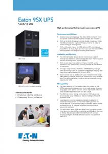
Split Shaft (Chelsea)
2
•
Used on medium-duty trucks that have applications requiring the torque capacity of an 8-Bolt PTO.
•
Provides 100% of input speed.
•
Mount in any orientation with the PTO shaft going to the front or rear of the truck.
•
Designed for Class 3, 4, 5, and 6 trucks with automatic transmissions and no PTO opening or trucks requiring additional PTO openings.
•
Several 6-Bolt and Reversible PTOs will fit on the 912 Series.
•
Three 8-Bolt openings that allow you to operate a variety of auxiliary equipment.
•
Wide variety of 6-Bolt, 8-Bolt, PowerShift, and Reversible PTOs fit the 912 Series.
•
Air and Lever shift available.
•
Split shaft PTOs can be used on all heavy-duty Fuller® manual, UltraShift PLUS, and AutoShift transmissions.
•
Medium-duty wet clutch transmissions will have split shaft PTO capability with the spring 2006 software release.
•
All other automated products do not have the ability to operate split shaft PTOs.
General Information
Split Shaft (Muncie)
General Information
•
Through torque to 21,600 lb-ft.
•
Output torque to 936 lb-ft.
•
1410 or 1500 Series companion flange outputs.
•
1500, 1600, 1700, 1800 Series main shaft flanges.
•
SAE “B”, “B-B”,”C”, “C-C” and “D” hydraulic mounts.
•
Air-shift operation.
•
Suitable for stationary or mobile applications.
•
Precision ground gearing for quiet operation.
•
Split shaft PTOs can be used on all heavy-duty Fuller® manual, UltraShift PLUS, and AutoShift transmissions.
•
Medium-duty wet clutch transmissions will have split shaft PTO capability with the spring 2006 software release.
•
All other automated products do not have the ability to operate split shaft PTOs.
3
PTO Adapters
Geared PTO Adapters Chelsea 626 Series •
Mounts a 6-Bolt PTO to a 6-Bolt transmission opening.
•
Moves the PTO straight out from the transmission.
•
Uses the same input gears as the 442 and 489 Series.
•
Uses the same mounting hardware and spacers used to mount a 442 Series to a specific application.
628 Series
4
•
Mounts a 6-Bolt PTO to a 6-Bolt transmission opening.
•
Moves the PTO straight out from the transmission.
•
Uses the same input gears as the 442 and 489 Series.
•
Uses the same mounting hardware and spacers used to mount a 489 Series to a specific application.
PTO Adapters
630 Series Mounts a 6-Bolt PTO to a 6-Bolt transmission opening.
•
Moves the PTO down at a 30° angle, helping to eliminate interference problems.
•
Uses the same input gears as the 442 and 489 Series.
•
Special 630-02 adapter designed for the Fuller® UltraShift transmission. When the 8-Bolt PTO opening is needed for PTO usage, this 30° adapter allows the movement of the high capacity inertia brake from the 8Bolt opening to the 6-Bolt opening and rotates the high capacity inertia brake to eliminate interference problems.
645 Series •
Mounts a 6-Bolt PTO to a 6-Bolt transmission opening.
•
Moves the PTO down at a 45° angle, helping to eliminate interference problems.
•
Uses the same input gears as the 442 and 489 Series.
•
Same mounting hardware and spacers used to mount a 442 Series to a specific application.
5
PTO Adapters
•
PTO Adapters
Muncie Single Gear Adapters •
Moves the 6-Bolt PTO flange outward away from the transmission.
Angular Adapters •
Various angles available.
•
55° adapter available for relocating high capacity inertia brake on heavy-duty Fuller® UltraShift transmissions.
8-Bolt to 6-Bolt Adapter •
6
Converts an 8-Bolt PTO opening into a 6-Bolt PTO opening.
PTO Adapters
Angular Offset Gear Adapter •
Offered in multiple gearing configurations.
•
All adapters offered with a 10° offset.
PTO Adapters
7
PTO Configurations
PTO Configurations by Model - Manual Medium-Duty Manual
Model
8-Bolt
Gear Info.
6-Bolt
Gear Info.
Thrushaft
Int. Spline Info.
Ext. Aux. Countershaft PTO1
Ext. Spline Info.
FS-4205A
N/A
FS-4205B
% of Transmission Engine Torque Limit for Speed PTO use (lb-ft)
N/A
Right & Left
28 Teeth 6.1P
N/A
N/A
N/A
N/A
46
N/A
N/A
Right & Left
28 Teeth 6.1P
N/A
N/A
N/A
N/A
53
FS-5205A
N/A
N/A
Right & Left
R=33 Teeth 7.0P, L=19 Teeth 6.1P
N/A
N/A
N/A
26 Teeth
L=44, R=46
FS-5205B
N/A
N/A
Right & Left
R=33 Teeth 7.0P, L=19 Teeth 6.1P
N/A
N/A
N/A
26 Teeth
L=52, R=54
FS-5406A
N/A
N/A
Right & Left
38 Teeth 6.35P
N/A
N/A
N/A
26 Teeth
52
FS-6305A
N/A
N/A
Right & Left
39 Teeth 6.35P
N/A
N/A
N/A
26 Teeth
46
FS-6305B
N/A
N/A
Right & Left
41 Teeth 6.5P
N/A
N/A
N/A
26 Teeth
46
FS-6406A
N/A
N/A
Right & Left
38T 6.35P 22DEG R.H. HELIX
N/A
N/A
N/A
26T 45DEG PA
52
FSB-5406B
N/A
N/A
Right & Left
38T 6.35P 22DEG R.H. HELIX
N/A
N/A
N/A
26T 45DEG PA
52
FSB-6406B
N/A
N/A
Right & Left
38T 6.35P 22DEG R.H. HELIX
N/A
N/A
N/A
26T 45DEG PA
52
FSO-6406A
N/A
N/A
Right & Left
48T 7.00P, 26DEG R.H. HELIX
N/A
N/A
N/A
26T 45DEG PA
68
FSO-8406A
N/A
N/A
Right & Left
48T 7.00P, 26DEG R.H. HELIX
N/A
N/A
N/A
26T 45DEG PA
68
500
Note: (1) - A rear mount PTO for Medium-Duty is available from Muncie Power Products, Inc.; however, it is not shown on this page. The rear mount PTO requires an adapter plate. Please contact Muncie Power Products for more information. 8
PTO Configurations
Model
8-Bolt Gear Info.
6-Bolt
Gear Info.
PTO Configurations
Heavy-Duty Manual Transmission - RT Series
Thrushaft
Int. Spline Info.
Ext. Aux. Countershaft PTO
Ext. Spline Info.
% of Engine Speed
Transmission Torque Limit for PTO use (lb-ft)
RT-6609A
Yes
33T 6.0P, 20DEG A
Yes
33T 6.0P, 20DEG A
N/A
N/A
N/A
N/A
72
350
RT-8709B
Yes
47T 6.0P, 20DEG PA
Yes4
45T 6.0P, 20DEG PA
Lower Left
32T 0.5P, 30DEG PA
N/A
N/A
70
5006
RT-11709H
Yes
47T 6.0P, 20DEG PA
Yes4
45T 6.0P, 20DEG PA
N/A
N/A
N/A
N/A
70
RT-12709H
Yes
47T 6.0P, 20DEG PA
Yes4
45T 6.0P, 20DEG PA
N/A
N/A
N/A
N/A
70
RT-13709H
Yes
47T 6.0P, 20DEG PA
Yes4
45T 6.0P, 20DEG PA
N/A
N/A
N/A
N/A
70
RT-14709H
Yes
47T 6.0P, 20DEG PA
Yes4
45T 6.0P, 20DEG PA
N/A
N/A
N/A
N/A
70
RTX-11609B
Yes
47T 6.0P, 20DEG PA
Yes4
45T 6.0P, 20DEG PA
N/A
N/A
N/A
N/A
79
RTX-12609B
Yes
47T 6.0P, 20DEG PA
Yes4
45T 6.0P, 20DEG PA
Lower Left
32T 0.5P, 30DEG PA
N/A
N/A
79
RTX-13609B
Yes
47T 6.0P, 20DEG PA
Yes4
45T 6.0P, 20DEG PA
Lower Left
32T 0.5P, 30DEG PA
N/A
N/A
79
RTX-14609B
Yes
47T 6.0P, 20DEG PA
Yes4
45T 6.0P, 20DEG PA
Lower Left
32T 0.5P, 30DEG PA
N/A
N/A
79
RTX-16709B
Yes
47T 6.0P, 20DEG PA
Yes4
45T 6.0P, 20DEG PA
Lower Left
32T 0.5P, 30DEG PA
N/A
N/A
79
T-14607A
Yes
47T 6.0P, 20DEG PA
Yes
45T 6.0P, 20DEG PA
N/A
N/A
N/A
N/A
51
T-14607B
Yes
47T 6.0P, 20DEG PA
Yes
45T 6.0P, 20DEG PA
N/A
N/A
N/A
N/A
51
TX-14607B
Yes
47T 6.0P, 20DEG PA
Yes
45T 6.0P, 20DEG PA
N/A
N/A
N/A
N/A
69
3505
Note: (4) - 6-bolt PTO will interfere with front mount oil filter. Rear or remote mount oil filter must be utilized. Note: (5) - Transmission may be ordered with heavy-duty input bearing (4301417) to allow a combined PTO output of 500 lb-ft (continuous) and 750 lb-ft (intermittent) torque. Note: (6) - Intermittent torque of up to 750 lb-ft at the countershaft is permitted for 5 minutes of each 15 minute PTO duty cycle. 9
PTO Configurations
Heavy-Duty Manual Transmission - RT Vocational
Model
8-Bolt Gear Info. 6-Bolt
Gear Info.
ThruShaft
Int. Spline Info.
Ext. Aux. Countershaft PTO
Ext. Spline Info.
% of Transmission Engine Torque Limit for Speed PTO use (lb-ft)
RT-8608L
Yes
47T 6.0P, 20DEG PA
Yes4
45T 6.0P, 20DEG PA
N/A
N/A
N/A
N/A
58
RT-8908LL
Yes
47T 6.0P, 20DEG PA
Yes4
45T 6.0P, 20DEG PA
N/A
N/A
N/A
N/A
70
RT-14915
Yes
47T 6.0P, 20DEG PA
Yes4
45T 6.0P, 20DEG PA
N/A
32T 0.5P, 30DEG PA
N/A
N/A
70
RTO-11908LL
Yes
47T 6.0P, 20DEG PA
Yes4
45T 6.0P, 20DEG PA
N/A
N/A
N/A
N/A
94
RTO-11909ALL
Yes
47T 6.0P, 20DEG PA
Yes4
45T 6.0P, 20DEG PA
N/A
N/A
N/A
N/A
79
RTO-14908LL
Yes
47T 6.0P, 20DEG PA
Yes4
45T 6.0P, 20DEG PA
Lower Left2
32T 0.5P, 30DEG PA
N/A
N/A
94
RTO-14909ALL
Yes
47T 6.0P, 20DEG PA
Yes
4
45T 6.0P, 20DEG PA
Lower Left2
32T 0.5P, 30DEG PA
N/A
N/A
79
RTO-14915
Yes
47T 6.0P, 20DEG PA
Yes4
45T 6.0P, 20DEG PA
N/A
32T 0.5P, 30DEG PA
N/A
N/A
89
RTO-16908LL
Yes
47T 6.0P, 20DEG PA
Yes4
45T 6.0P, 20DEG PA
Lower Left2
32T 0.5P, 30DEG PA
N/A
N/A
94
RTO-16909ALL
Yes
47T 6.0P, 20DEG PA
Yes4
45T 6.0P, 20DEG PA
Lower Left2
32T 0.5P, 30DEG PA
N/A
N/A
79
RTO-16915
Yes
47T 6.0P, 20DEG PA
Yes4
45T 6.0P, 20DEG PA
N/A
32T 0.5P, 30DEG PA
N/A
N/A
89
3505
5006
Note: (2) - Oil pump required. Note: (4) - 6-bolt PTO will interfere with front mount oil filter. Rear or remote mount oil filter must be utilized. Note: (5) - Transmission may be ordered with heavy-duty input bearing (4301417) to allow a combined PTO output of 500 lb-ft (continuous) and 750 lb-ft (intermittent) torque. Note: (6) - Intermittent torque of up to 750 lb-ft at the countershaft is permitted for 5 minutes of each 15 minute PTO duty cycle. 10
PTO Configurations
Model
8-Bolt
Gear Info.
6-Bolt
Gear Info.
ThruInt. Shaft Spline Info.
PTO Configurations
Heavy-Duty Manual Transmission - RT Performance
Ext. Aux. Countershaft PTO
Ext. Spline Info.
% of Engine Speed
Transmission Torque Limit for PTO use (lb-ft)
RTLO-12913A
Yes
47T 6.0P, 20DEG PA
Yes4
45T 6.0P, 20DEG PA
N/A
N/A
N/A
N/A
79
RTLO-14913A
Yes
47T 6.0P, 20DEG PA
Yes4
45T 6.0P, 20DEG PA
N/A
N/A
N/A
N/A
79
RTLO-14918B
Yes
47T 6.0P, 20DEG PA
Yes4
45T 6.0P, 20DEG PA
N/A
N/A
N/A
N/A
79
RTLO-16913A
Yes
47T 6.0P, 20DEG PA
Yes4
45T 6.0P, 20DEG PA
N/A
N/A
N/A
N/A
79
RTLO-16918B
Yes
47T 6.0P, 20DEG PA
Yes4
45T 6.0P, 20DEG PA
N/A
N/A
N/A
N/A
79
RTLO-18913A
Yes
47T 6.0P, 20DEG PA
Yes4
45T 6.0P, 20DEG PA
N/A
N/A
N/A
N/A
79
RTLO-18918B
Yes
47T 6.0P, 20DEG PA
Yes4
45T 6.0P, 20DEG PA
N/A
N/A
N/A
N/A
79
RTLO-20913A
Yes
47T 6.0P, 20DEG PA
Yes4
45T 6.0P, 20DEG PA
N/A
N/A
N/A
N/A
79
RTLO-20918B
Yes
47T 6.0P, 20DEG PA
Yes4
45T 6.0P, 20DEG PA
N/A
N/A
N/A
N/A
79
RTLO-22918B
Yes
47T 6.0P, 20DEG PA
Yes4
45T 6.0P, 20DEG PA
N/A
N/A
N/A
N/A
79
5006
RTLOC-16909A-T2
Yes
47T 6.0P, 20DEG PA
Yes4
45T 6.0P, 20DEG PA
N/A
N/A
N/A
N/A
79
3505
RTLOC-18909A-T2
Yes
47T 6.0P, 20DEG PA
Yes4
45T 6.0P, 20DEG PA
N/A
N/A
N/A
N/A
79
5006
RTOC-16909A
Yes
47T 6.0P, 20DEG PA
Yes4
45T 6.0P, 20DEG PA
N/A
N/A
N/A
N/A
79
3505
RTOC-18909A
Yes
47T 6.0P, 20DEG PA
Yes4
45T 6.0P, 20DEG PA
N/A
N/A
N/A
N/A
79
5006
RTOCM-16909A
Yes
47T 6.0P, 20DEG PA
Yes4
45T 6.0P, 20DEG PA
N/A
N/A
N/A
N/A
79
3505
3505
Note: (4) - 6-bolt PTO will interfere with front mount oil filter. Rear or remote mount oil filter must be utilized. Note: (5) - Transmission may be ordered with heavy-duty input bearing (4301417) to allow a combined PTO output of 500 lb-ft (continuous) and 750 lb-ft (intermittent) torque. Note: (6) - Intermittent torque of up to 750 lb-ft at the countershaft is permitted for 5 minutes of each 15 minute PTO duty cycle.
11
PTO Configurations
Heavy-Duty Manual Transmission - Fuller Advantage Series
Model
FA-14810B
8-Bolt Gear Info. 6-Bolt Gear Info.
ThruShaft
Int. Spline Info.
Ext. Aux. Countershaft PTO
Ext. Spline Info.
% of Engine Speed
Yes
47T 6.0P, 20DEG PA
Yes4
45T 6.0P, 20DEG PA
32T 0.5P, 30DEG PA
N/A
N/A
70
Yes
47T 6.0P, 20DEG PA
Yes4
45T 6.0P, 20DEG PA
32T 0.5P, 30DEG PA
N/A
N/A
70
FAM-14810B
Yes
47T 6.0P, 20DEG PA
Yes4
45T 6.0P, 20DEG PA
32T 0.5P, 30DEG PA
N/A
N/A
70
FAM-15810B
Yes
47T 6.0P, 20DEG PA
Yes4
45T 6.0P, 20DEG PA
32T 0.5P, 30DEG PA
N/A
N/A
70
FAOM-14810C
Yes
47T 6.0P, 20DEG PA
Yes4
45T 6.0P, 20DEG PA
32T 0.5P, 30DEG PA
N/A
N/A
79
FAOM-15810C
Yes
47T 6.0P, 20DEG PA
Yes4
45T 6.0P, 20DEG PA
32T 0.5P, 30DEG PA
N/A
N/A
79
Yes
47T 6.0P, 20DEG PA
Yes4
45T 6.0P, 20DEG PA
32T 0.5P, 30DEG PA
N/A
N/A
79
FAO-11810C
Yes
47T 6.0P, 20DEG PA
Yes4
45T 6.0P, 20DEG PA
32T 0.5P, 30DEG PA
N/A
N/A
79
FAO-12810C
Yes
47T 6.0P, 20DEG PA
Yes4
45T 6.0P, 20DEG PA
32T 0.5P, 30DEG PA
N/A
N/A
79
FAO-13810C
Yes
47T 6.0P, 20DEG PA
Yes4
45T 6.0P, 20DEG PA
32T 0.5P, 30DEG PA
N/A
N/A
79
FAO-14810C
Yes
47T 6.0P, 20DEG PA
Yes4
45T 6.0P, 20DEG PA
32T 0.5P, 30DEG PA
N/A
N/A
79
FAO-15810C
Yes
47T 6.0P, 20DEG PA
Yes4
45T 6.0P, 20DEG PA
32T 0.5P, 30DEG PA
N/A
N/A
79
FAO-16810C
Yes
47T 6.0P, 20DEG PA
Yes4
45T 6.0P, 20DEG PA
32T 0.5P, 30DEG PA
N/A
N/A
79
FA-15810B
FAOM-16810C
Available upon request with application review
Transmission Torque Limit for PTO use (lb-ft)
5006
Note: (4) - 6-bolt PTO will interfere with front mount oil filter. Rear or remote mount oil filter must be utilized. Note: (5) - Transmission may be ordered with heavy-duty input bearing (4301417) to allow a combined PTO output of 500 lb-ft (continuous) and 750 lb-ft (intermittent) torque. Note: (6) - Intermittent torque of up to 750 lb-ft at the countershaft is permitted for 5 minutes of each 15 minute PTO duty cycle.
12
PTO Configurations
PTO Configurations
Heavy-Duty Manual Transmission - FR Series
Note: (LL) Lower Left, (UR) Upper Right Model
8-Bolt Gear Info. 6-Bolt
Gear Info.
ThruShaft
Int. Spline Info.
Ext. Aux. Countershaft PTO
Ext. % of Transmission Spline Engine Torque Limit for Info. Speed PTO use (lb-ft)
FR-11210B
Yes
47T 6.0P, 20DEG PA
Yes9
45T 6.0P, 20DEG PA
LL & UR
32T 0.5P, 30DEG PA
N/A
N/A
65
FR-12210B
Yes
47T 6.0P, 20DEG PA
Yes9
45T 6.0P, 20DEG PA
LL & UR
32T 0.5P, 30DEG PA
N/A
N/A
65
FR-13210B
Yes
47T 6.0P, 20DEG PA
Yes9
45T 6.0P, 20DEG PA
LL & UR
32T 0.5P, 30DEG PA
N/A
N/A
65
FR-14210B
Yes
47T 6.0P, 20DEG PA
Yes9
45T 6.0P, 20DEG PA
LL & UR
32T 0.5P, 30DEG PA
N/A
N/A
65
FR-15210B
Yes
47T 6.0P, 20DEG PA
Yes9
45T 6.0P, 20DEG PA
LL & UR
32T 0.5P, 30DEG PA
N/A
N/A
65
FRW-15210B
Yes
47T 6.0P, 20DEG PA
Yes9
45T 6.0P, 20DEG PA
LL & UR
32T 0.5P, 30DEG PA
N/A
N/A
65
FRM-15210B
Yes
47T 6.0P, 20DEG PA
Yes9
45T 6.0P, 20DEG PA
LL & UR
32T 0.5P, 30DEG PA
N/A
N/A
87
FR-9210B
Yes
47T 6.0P, 20DEG PA
Yes9
45T 6.0P, 20DEG PA
LL & UR
32T 0.5P, 30DEG PA
N/A
N/A
65
FRO-11210B
Yes
47T 6.0P, 20DEG PA
Yes9
45T 6.0P, 20DEG PA
LL & UR
32T 0.5P, 30DEG PA
N/A
N/A
87
FRO-11210C
Yes
47T 6.0P, 20DEG PA
Yes9
45T 6.0P, 20DEG PA
LL & UR
32T 0.5P, 30DEG PA
N/A
N/A
84
FRO-12210B
Yes
47T 6.0P, 20DEG PA
Yes9
45T 6.0P, 20DEG PA
LL & UR
32T 0.5P, 30DEG PA
N/A
N/A
87
FRO-12210C
Yes
47T 6.0P, 20DEG PA
Yes9
45T 6.0P, 20DEG PA
LL & UR
32T 0.5P, 30DEG PA
N/A
N/A
84
FRO-13210B
Yes
47T 6.0P, 20DEG PA
Yes9
45T 6.0P, 20DEG PA
LL & UR
32T 0.5P, 30DEG PA
N/A
N/A
87
5006
Note: (6) - Intermittent torque of up to 750 lb-ft at the countershaft is permitted for 5 minutes of each 15 minute PTO duty cycle. Note: (9) - 6-Bolt Option not available on Integral Oil Cooler Case.
13
PTO Configurations
Model
8-Bolt Gear Info.
6-Bolt
Gear Info.
ThruShaft
Int. Spline Info.
Ext. Aux. Countershaft PTO
Ext. Spline Info.
% of TransmisEngine sion Torque Speed Limit for PTO use (lb-ft)
FRO-13210C
Yes
47T 6.0P, 20DEG PA
Yes9
45T 6.0P, 20DEG PA
LL & UR
32T 0.5P, 30DEG PA
N/A
N/A
84
FRO-14210B
Yes
47T 6.0P, 20DEG PA
Yes9
45T 6.0P, 20DEG PA
LL & UR
32T 0.5P, 30DEG PA
N/A
N/A
87
FRO-14210C
Yes
47T 6.0P, 20DEG PA
Yes9
45T 6.0P, 20DEG PA
LL & UR
32T 0.5P, 30DEG PA
N/A
N/A
84
FRO-15210B
Yes
47T 6.0P, 20DEG PA
Yes9
45T 6.0P, 20DEG PA
LL & UR
32T 0.5P, 30DEG PA
N/A
N/A
87
FRO-15210C
Yes
47T 6.0P, 20DEG PA
Yes9
45T 6.0P, 20DEG PA
LL & UR
32T 0.5P, 30DEG PA
N/A
N/A
84
FRO-16210B
Yes
47T 6.0P, 20DEG PA
Yes9
45T 6.0P, 20DEG PA
LL & UR
32T 0.5P, 30DEG PA
N/A
N/A
87
FRO-16210C
Yes
47T 6.0P, 20DEG PA
Yes9
45T 6.0P, 20DEG PA
LL & UR
32T 0.5P, 30DEG PA
N/A
N/A
84
FRO-17210C
Yes
47T 6.0P, 20DEG PA
Yes9
45T 6.0P, 20DEG PA
LL & UR
32T 0.5P, 30DEG PA
N/A
N/A
84
FRO-18210C
Yes
47T 6.0P, 20DEG PA
Yes9
45T 6.0P, 20DEG PA
LL & UR
32T 0.5P, 30DEG PA
N/A
N/A
84
5006
Note: (6) - Intermittent torque of up to 750 lb-ft at the countershaft is permitted for 5 minutes of each 15 minute PTO duty cycle. Note: (9) - 6-Bolt Option not available on Integral Oil Cooler Case.
14
PTO Configurations
Model
8-Bolt
Gear Info.
6-Bolt
Gear Info.
AT-1202
Yes
30T 5.0P, 20DEG PA
Yes
2A-92
No
N/A
No
PTO Configurations
Heavy-Duty Manual Transmission - Auxiliary Transmissions
ThruShaft
Int. Spline Info.
Ext. Aux. Countershaft PTO
Ext. Spline Info.
% of Transmission Engine Torque Limit for Speed PTO use (lb-ft)
30T 5.0P, 20DEG PA
N/A
N/A
N/A
N/A
93
5006
N/A
N/A
N/A
N/A
N/A
N/A
N/A
Note: (6) - Intermittent torque of up to 750 lb-ft at the countershaft is permitted for 5 minutes of each 15 minute PTO duty cycle.
15
PTO Configurations
PTO Configurations by Model - Automated PTO and Auto Neutral Availability Split Shaft PTO
Countershaft PTO**
Auto Neutral
MD Hybrid
N/A
Available (Default)
Available (Default)
UltraShift AW3
Available
Available (Default)
Available (Default)
UltraShift HV
N/A
Available (Default)
N/A
AutoShift
Available
Available (Default)
N/A
UltraShift DM3
N/A
Available (Default)
N/A
Fuller Advantage
Available
Available (Default)
Available (Default)
UltraShift PLUS
Available
Available (Default)
Available (Default)
Note: ** Thru-Shaft, extended countershaft, and extended auxiliary countershaft PTO availability can be found in the PTO Configuration by Model sections.
16
PTO Configurations
Model
8-Bolt
Gear Info.
F-5405B-DM3
N/A
F-5505B-DM3
PTO Configurations
Medium-Duty Automated
6-Bolt
Gear Info.
ThruInt. Ext. Aux. Shaft Spline CounterInfo. shaft PTO1
Ext. Spline Info.
% of Transmission Engine Torque Limit for Speed PTO use (lb-ft)
N/A
Left or Right2
48T 7.00P, 26DEG R.H. HELIX
N/A
N/A
Yes
26T 45DEG PA
67
N/A
N/A
Left or Right2
48T 7.00P, 26DEG R.H. HELIX
N/A
N/A
Yes
26T 45DEG PA
67
F-6405B-DM3
N/A
N/A
Left or Right2
48T 7.00P, 26DEG R.H. HELIX
N/A
N/A
Yes
26T 45DEG PA
67
FO-5406B-DM3
N/A
N/A
Left or Right2
48T 7.00P, 26DEG R.H. HELIX
N/A
N/A
Yes
26T 45DEG PA
67
FO-5506B-DM3
N/A
N/A
Left or Right2
48T 7.00P, 26DEG R.H. HELIX
N/A
N/A
Yes
26T 45DEG PA
67
FO-6406B-DM3
N/A
N/A
Left or Right2
48T 7.00P, 26DEG R.H. HELIX
N/A
N/A
Yes
26T 45DEG PA
67
FO-6506B-DM3
N/A
N/A
Left or Right2
48T 7.00P, 26DEG R.H. HELIX
N/A
N/A
Yes
26T 45DEG PA
67
FO-6406A-ASX
N/A
N/A
Right Only
48T 7.00P, 26DEG R.H. HELIX
N/A
N/A
Yes
26T 45DEG PA
67
FO-8406A-ASX
N/A
N/A
Right Only
48T 7.00P, 26DEG R.H. HELIX
N/A
N/A
Yes
26T 45DEG PA
67
FO-6406A-AW3
N/A
N/A
Right Only
48T 7.00P, 26DEG R.H. HELIX
N/A
N/A
Yes
26T 45DEG PA
67
FO-8406A-AW3
N/A
N/A
Right Only
48T 7.00P, 26DEG R.H. HELIX
N/A
N/A
Yes
26T 45DEG PA
67
500
Note: (1) - A rear-mount PTO for medium-duty transmissions is available from Muncie Power Products; however, it is not shown on this page. The rear-mount PTO requires an adapter plate. Please contact Muncie Power Products for more information. Note: (2) - Inertia brake can be moved from left-side 6-bolt opening to right-side 6-bolt opening. (Kit Number K-3742 is required to move).
17
PTO Configurations
Medium-Duty Dual Clutch - Procision
Model
EDCO-6F107A EDCO-6F107A-P
8-Bolt
Gear Info.
N/A N/A
EDCO-6F107A-M
N/A
EDCO-6F107A-B
N/A
L= 23T LH Helix 5.64P 20DEG PA R= 47T RH Helix 8.975P 17DEG PA
6-Bolt Gear Info. ThruShaft
Int. Spline Info.
Ext. Aux. Countershaft PTO
Left or Right
45T 6.0P, 20DEG PA
N/A
N/A
Yes
Left or Right
45T 6.0P, 20DEG PA
N/A
N/A
Yes
Left or Right
45T 6.0P, 20DEG PA
N/A
N/A
Yes
Left or Right
45T 6.0P, 20DEG PA
N/A
N/A
No
Note: (7) - Minimum Engine Speed 1100 RPM. Includes all PTOs in operation. Note: (8) - Second clutch closed.
18
Ext. Spline Info.
400mm 12T 20DEG PA
N/A
% of Transmission Engine Torque Limit for Speed8 PTO use (lb-ft)7
L=39 R=82
500
PTO Configurations
Model
8-Bolt
Gear Info.
EH-6E706B-BP
N/A
EH-6E706B-CD
PTO Configurations
Medium-Duty Hybrid
6-Bolt
Gear Info.
ThruInt. Ext. Aux. Shaft Spline Countershaft Info. PTO
Ext. Spline Info.
% of Transmission Engine Torque Limit for Speed PTO use (lb-ft)
N/A
Left or Right
48T 7.00P, 26DEG R.H. HELIX
N/A
N/A
Yes
26T 45DEG PA
67
N/A
N/A
Left or Right
48T 7.00P, 26DEG R.H. HELIX
N/A
N/A
Yes
26T 45DEG PA
67
EH-8E406A-CD
N/A
N/A
Left or Right
48T 7.00P, 26DEG R.H. HELIX
N/A
N/A
Yes
26T 45DEG PA
67
EH-8E406A-CDG
N/A
N/A
Left or Right
48T 7.00P, 26DEG R.H. HELIX
N/A
N/A
Yes
26T 45DEG PA
67
EH-8E406A-CDR
N/A
N/A
Left or Right
48T 7.00P, 26DEG R.H. HELIX
N/A
N/A
Yes
26T 45DEG PA
67
EH-8E406A-P
N/A
N/A
Left or Right
48T 7.00P, 26DEG R.H. HELIX
N/A
N/A
Yes
26T 45DEG PA
67
EH-8FA0406A-PSB
N/A
N/A
Left or Right
48T 7.00P, 26DEG R.H. HELIX
N/A
N/A
Yes
26T 45DEG PA
67
EH-8E406A-T
N/A
N/A
Left or Right
48T 7.00P, 26DEG R.H. HELIX
N/A
N/A
Yes
26T 45DEG PA
67
EH-8E406A-UP
N/A
N/A
Left or Right
48T 7.00P, 26DEG R.H. HELIX
N/A
N/A
Yes
26T 45DEG PA
67
EH-8E406A-UPG
N/A
N/A
Left or Right
48T 7.00P, 26DEG R.H. HELIX
N/A
N/A
Yes
26T 45DEG PA
67
EH-6E706B-UPG
N/A
N/A
Left or Right
48T 7.00P, 26DEG R.H. HELIX
N/A
N/A
Yes
26T 45DEG PA
67
500
Note: (1) - A rear-mount PTO for medium-duty transmissions is available from Muncie Power Products; however, it is not shown on this page. The rear-mount PTO requires an adapter plate. Please contact Muncie Power Products for more information.
19
PTO Configurations
Heavy-Duty Automated - AutoShift / UltraShift / UltraShift PLUS 10-Speeds
Model
8-Bolt
Gear Info.
6-Bolt Gear Info.
ThruShaft
Int. Spline Info.
Ext. Aux. Countershaft PTO
Ext. Spline Info.
% of Transmission Engine Torque Limit for Speed PTO use (lb-ft)
FO-10E310C-VAS
Yes
47T 6.0P, 20DEG PA
Yes4
45T 6.0P, 20DEG PA
Lower Left
32T 0.5P, 30DEG PA
N/A
N/A
79
RTO-10910B-AS3
Yes
47T 6.0P, 20DEG PA
Yes
45T 6.0P, 20DEG PA
Lower Left
32T 0.5P, 30DEG PA
N/A
N/A
94
RTO-10910B-DM3
Yes
47T 6.0P, 20DEG PA
Yes
45T 6.0P, 20DEG PA
Lower Left
32T 0.5P, 30DEG PA
N/A
N/A
94
FO-12E310C-VAS
Yes
47T 6.0P, 20DEG PA
Yes4
45T 6.0P, 20DEG PA
Lower Left
32T 0.5P, 30DEG PA
N/A
N/A
79
RTO-12910B-AS3
Yes
47T 6.0P, 20DEG PA
Yes
45T 6.0P, 20DEG PA
Lower Left
32T 0.5P, 30DEG PA
N/A
N/A
94
RTO-12910B-DM3
Yes
47T 6.0P, 20DEG PA
Yes
45T 6.0P, 20DEG PA
Lower Left
32T 0.5P, 30DEG PA
N/A
N/A
94
FO-14E310C-VAS
Yes
47T 6.0P, 20DEG PA
Yes4
45T 6.0P, 20DEG PA
Lower Left
32T 0.5P, 30DEG PA
N/A
N/A
79
FO-14E310C-LAS
Yes
47T 6.0P, 20DEG PA
Yes4
45T 6.0P, 20DEG PA
Lower Left
32T 0.5P, 30DEG PA
N/A
N/A
79
FOM-14E310C-LAS
Yes
47T 6.0P, 20DEG PA
Yes4
45T 6.0P, 20DEG PA
Lower Left
32T 0.5P, 30DEG PA
N/A
N/A
79
FOM-14E310C-VAS
Yes
47T 6.0P, 20DEG PA
Yes4
45T 6.0P, 20DEG PA
Lower Left
32T 0.5P, 30DEG PA
N/A
N/A
79
FM-14E310B-LAS
Yes
47T 6.0P, 20DEG PA
Yes4
45T 6.0P, 20DEG PA
Lower Left
32T 0.5P, 30DEG PA
N/A
N/A
70
RTO-14910B-AS3
Yes
47T 6.0P, 20DEG PA
Yes4
45T 6.0P, 20DEG PA
Lower Left
32T 0.5P, 30DEG PA
N/A
N/A
94
RTO-14910B-DM3
Yes
47T 6.0P, 20DEG PA
Yes4
45T 6.0P, 20DEG PA
Lower Left
32T 0.5P, 30DEG PA
N/A
N/A
94
FM-14D310B-LST
Yes
47T 6.0P, 20DEG PA
Yes4
45T 6.0P, 20DEG PA
Lower Left
32T 0.5P, 30DEG PA
N/A
N/A
94
5006
3505
5006
3505
Note: (4) - 6-bolt PTO will interfere with front mount oil filter. Rear or remote mount oil filter must be utilized. Note: (5) - Transmission may be ordered with heavy-duty input bearing (4301417) to allow a combined PTO output of 500 lb-ft (continuous) and 750 lb-ft (intermittent) torque. Note: (6) - Intermittent torque of up to 750 lb-ft at the countershaft is permitted for 5 minutes of each 15 minute PTO duty cycle.
20
PTO Configurations
8-Bolt
Gear Info.
6-Bolt Gear Info.
ThruShaft
Int. Spline Info.
Ext. Aux. Countershaft PTO
Ext. % of Transmission Spline Engine Torque Limit for Info. Speed PTO use (lb-ft)
RTO-14910C-AS3
Yes
47T 6.0P, 20DEG PA
Yes4
45T 6.0P, 20DEG PA
Lower Left
32T 0.5P, 30DEG PA
N/A
N/A
79
FOM-15E310C-LAS
Yes
47T 6.0P, 20DEG PA
Yes4
45T 6.0P, 20DEG PA
Lower Left
32T 0.5P, 30DEG PA
N/A
N/A
79
FOM-15E310C-VAS
Yes
47T 6.0P, 20DEG PA
Yes4
45T 6.0P, 20DEG PA
Lower Left
32T 0.5P, 30DEG PA
N/A
N/A
79
FM-15E310B-LAS
Yes
47T 6.0P, 20DEG PA
Yes4
45T 6.0P, 20DEG PA
Lower Left
32T 0.5P, 30DEG PA
N/A
N/A
70
FM-15D310B-LST
Yes
47T 6.0P, 20DEG PA
Yes4
45T 6.0P, 20DEG PA
Lower Left
32T 0.5P, 30DEG PA
N/A
N/A
94
FO-16E310C-LAS
Yes
47T 6.0P, 20DEG PA
Yes4
45T 6.0P, 20DEG PA
Lower Left
32T 0.5P, 30DEG PA
N/A
N/A
79
FO-16E310C-VAS
Yes
47T 6.0P, 20DEG PA
Yes4
45T 6.0P, 20DEG PA
Lower Left
32T 0.5P, 30DEG PA
N/A
N/A
79
FOM-16E310C-LAS
Yes
47T 6.0P, 20DEG PA
Yes4
45T 6.0P, 20DEG PA
Lower Left
32T 0.5P, 30DEG PA
N/A
N/A
79
FOM-16E310C-VAS
Yes
47T 6.0P, 20DEG PA
Yes4
45T 6.0P, 20DEG PA
Lower Left
32T 0.5P, 30DEG PA
N/A
N/A
79
RTO-16910B-AS3
Yes
47T 6.0P, 20DEG PA
Yes4
45T 6.0P, 20DEG PA
Lower Left
32T 0.5P, 30DEG PA
N/A
N/A
94
RTO/M-16910B-DM3
Yes
47T 6.0P, 20DEG PA
Yes4
45T 6.0P, 20DEG PA
Lower Left
32T 0.5P, 30DEG PA
N/A
N/A
94
RTO-16910C-AS3
Yes
47T 6.0P, 20DEG PA
Yes4
45T 6.0P, 20DEG PA
Lower Left
32T 0.5P, 30DEG PA
N/A
N/A
79
RTO-18910B-AS3
Yes
47T 6.0P, 20DEG PA
Yes4
45T 6.0P, 20DEG PA
Lower Left
32T 0.5P, 30DEG PA
N/A
N/A
94
3505
5006
3505
5006
3505
Note: (4) - 6-bolt PTO will interfere with front mount oil filter. Rear or remote mount oil filter must be utilized. Note: (5) - Transmission may be ordered with heavy-duty input bearing (4301417) to allow a combined PTO output of 500 lb-ft (continuous) and 750 lb-ft (intermittent) torque. Note: (6) - Intermittent torque of up to 750 lb-ft at the countershaft is permitted for 5 minutes of each 15 minute PTO duty cycle.
21
PTO Configurations
Model
PTO Configurations
Heavy-Duty Automated - Fuller Advantage Series Model
8-Bolt
Gear Info.
6-Bolt Gear Info.
ThruShaft
Int. Spline Info.
Ext. Aux. Countershaft PTO
Ext. % of Transmission Spline Engine Torque Limit for Info. Speed PTO use (lb-ft)
FAOM-13810S-EC3
Yes
47T 6.0P, 20DEG PA
Yes4
45T 6.0P, 20DEG PA
Lower Left
32T 0.5P, 30DEG PA
N/A
N/A
79
FAOM-14810S-EC3
Yes
47T 6.0P, 20DEG PA
Yes4
45T 6.0P, 20DEG PA
Lower Left
32T 0.5P, 30DEG PA
N/A
N/A
79
FAOM-15810S-EC3
Yes
47T 6.0P, 20DEG PA
Yes4
45T 6.0P, 20DEG PA
Lower Left
32T 0.5P, 30DEG PA
N/A
N/A
79
FAOM-15810S-EP3
Yes
47T 6.0P, 20DEG PA
Yes4
45T 6.0P, 20DEG PA
Lower Left
32T 0.5P, 30DEG PA
N/A
N/A
79
FAO-16810S-EP3
Yes
47T 6.0P, 20DEG PA
Yes4
45T 6.0P, 20DEG PA
Lower Left
32T 0.5P, 30DEG PA
N/A
N/A
79
FAO-16810S-EN3
Yes
47T 6.0P, 20DEG PA
Yes4
45T 6.0P, 20DEG PA
Lower Left
32T 0.5P, 30DEG PA
N/A
N/A
79
FAOM-15810S-EN3
Yes
47T 6.0P, 20DEG PA
Yes4
45T 6.0P, 20DEG PA
Lower Left
32T 0.5P, 30DEG PA
N/A
N/A
79
FAO-14810C-EA3
Yes
47T 6.0P, 20DEG PA
Yes4
45T 6.0P, 20DEG PA
Lower Left
32T 0.5P, 30DEG PA
N/A
N/A
79
FAO-16810C-EA3
Yes
47T 6.0P, 20DEG PA
Yes4
45T 6.0P, 20DEG PA
Lower Left
32T 0.5P, 30DEG PA
N/A
N/A
79
FAOM-15810C-EA3
Yes
47T 6.0P, 20DEG PA
Yes4
45T 6.0P, 20DEG PA
Lower Left
32T 0.5P, 30DEG PA
N/A
N/A
79
FAOM-16810C-EA3
Yes
47T 6.0P, 20DEG PA
Yes4
45T 6.0P, 20DEG PA
Lower Left
32T 0.5P, 30DEG PA
N/A
N/A
79
FAM-14810B-EA3
Yes
47T 6.0P, 20DEG PA
Yes4
45T 6.0P, 20DEG PA
Lower Left
32T 0.5P, 30DEG PA
N/A
N/A
79
FAM-15810B-EA3
Yes
47T 6.0P, 20DEG PA
Yes4
45T 6.0P, 20DEG PA
Lower Left
32T 0.5P, 30DEG PA
N/A
N/A
79
RTO-16910B-AS3
Yes
47T 6.0P, 20DEG PA
Yes4
45T 6.0P, 20DEG PA
Lower Left
32T 0.5P, 30DEG PA
N/A
N/A
94
RTO/M-16910B-DM3
Yes
47T 6.0P, 20DEG PA
Yes4
45T 6.0P, 20DEG PA
Lower Left
32T 0.5P, 30DEG PA
N/A
N/A
94
RTO-16910C-AS3
Yes
47T 6.0P, 20DEG PA
Yes4
45T 6.0P, 20DEG PA
Lower Left
32T 0.5P, 30DEG PA
N/A
N/A
79
FO-18E310C-LAS
Yes
47T 6.0P, 20DEG PA
Yes4
45T 6.0P, 20DEG PA
Lower Left
32T 0.5P, 30DEG PA
N/A
N/A
79
5006
RTO-18910B-AS3
Yes
47T 6.0P, 20DEG PA
Yes4
45T 6.0P, 20DEG PA
Lower Left
32T 0.5P, 30DEG PA
N/A
N/A
94
3505
5006
3505
Note: (4) - 6-bolt PTO will interfere with front mount oil filter. Rear or remote mount oil filter must be utilized. Note: (5) - Transmission may be ordered with heavy-duty input bearing (4301417) to allow a combined PTO output of 500 lb-ft (continuous) and 750 lb-ft (intermittent) torque. Note: (6) - Intermittent torque of up to 750 lb-ft at the countershaft is permitted for 5 minutes of each 15 minute PTO duty cycle.
22
PTO Configurations
8-Bolt
Gear Info.
6-Bolt Gear Info.
ThruShaft
Int. Spline Info.
Ext. Aux. Countershaft PTO
Ext. % of Transmission Spline Engine Torque Limit for Info. Speed PTO use (lb-ft)
FAOM-14810S-EC3
Yes
47T 6.0P, 20DEG PA
Yes4
45T 6.0P, 20DEG PA
Lower Left
32T 0.5P, 30DEG PA
N/A
N/A
79
FAOM-15810S-EC3
Yes
47T 6.0P, 20DEG PA
Yes4
45T 6.0P, 20DEG PA
Lower Left
32T 0.5P, 30DEG PA
N/A
N/A
79
FAOM-15810S-EP3
Yes
47T 6.0P, 20DEG PA
Yes4
45T 6.0P, 20DEG PA
Lower Left
32T 0.5P, 30DEG PA
N/A
N/A
79
FAO-16810S-EP3
Yes
47T 6.0P, 20DEG PA
4
Yes
45T 6.0P, 20DEG PA
Lower Left
32T 0.5P, 30DEG PA
N/A
N/A
79
FAOM-15810S-EN3
Yes
47T 6.0P, 20DEG PA
Yes4
45T 6.0P, 20DEG PA
Lower Left
32T 0.5P, 30DEG PA
N/A
N/A
79
FAO-16810S-EN3
Yes
47T 6.0P, 20DEG PA
Yes4
45T 6.0P, 20DEG PA
Lower Left
32T 0.5P, 30DEG PA
N/A
N/A
79
5006
Note: (4) - 6-bolt PTO will interfere with front mount oil filter. Rear or remote mount oil filter must be utilized. Note: (5) - Transmission may be ordered with heavy-duty input bearing (4301417) to allow a of combined PTO output of 500 lbft (continuous) and 750 lb-ft (intermittent) torque. Note: (6) - Intermittent torque of up to 750 lb-ft at the countershaft is permitted for 5 minutes of each 15 minute PTO duty cycle.
23
PTO Configurations
Model
PTO Configurations
Heavy-Duty Automated - UltraShift PLUS - VCS and VMS
Model
8-Bolt Gear Info. 6-Bolt
Gear Info.
ThruShaft
Int. Spline Info.
Ext. Aux. Ext. % of Transmission Counter- Spline Engine Torque Limit for shaft PTO Info. Speed PTO use (lb-ft)
FO-10E308LL-VCS
Yes
47T 6.0P, 20DEG PA
Yes4
45T 6.0P, 20DEG PA
Lower Left
32T 0.5P, 30DEG PA
N/A
N/A
94
FO-11E308LL-VCS
Yes
47T 6.0P, 20DEG PA
Yes4
45T 6.0P, 20DEG PA
Lower Left
32T 0.5P, 30DEG PA
N/A
N/A
94
FO-12E308LL-VCS
Yes
47T 6.0P, 20DEG PA
Yes4
45T 6.0P, 20DEG PA
Lower Left
32T 0.5P, 30DEG PA
N/A
N/A
94
FO-14E308LL-VCS
Yes
47T 6.0P, 20DEG PA
Yes4
45T 6.0P, 20DEG PA
Lower Left
32T 0.5P, 30DEG PA
N/A
N/A
94
FO-16E308LL-VCS
Yes
47T 6.0P, 20DEG PA
Yes4
45T 6.0P, 20DEG PA
Lower Left
32T 0.5P, 30DEG PA
N/A
N/A
94
FO-17E308LL-VCS
Yes
47T 6.0P, 20DEG PA
Yes4
45T 6.0P, 20DEG PA
Lower Left
32T 0.5P, 30DEG PA
N/A
N/A
94
FO-10E309ALL-VMS
Yes
47T 6.0P, 20DEG PA
Yes4
45T 6.0P, 20DEG PA
Lower Left
32T 0.5P, 30DEG PA
N/A
N/A
79
FO-11E309ALL-VMS
Yes
47T 6.0P, 20DEG PA
Yes4
45T 6.0P, 20DEG PA
Lower Left
32T 0.5P, 30DEG PA
N/A
N/A
79
FO-12E309ALL-VMS
Yes
47T 6.0P, 20DEG PA
Yes4
45T 6.0P, 20DEG PA
Lower Left
32T 0.5P, 30DEG PA
N/A
N/A
79
FO-14E309ALL-VMS
Yes
47T 6.0P, 20DEG PA
Yes4
45T 6.0P, 20DEG PA
Lower Left
32T 0.5P, 30DEG PA
N/A
N/A
79
FO-16E309ALL-VMS
Yes
47T 6.0P, 20DEG PA
Yes4
45T 6.0P, 20DEG PA
Lower Left
32T 0.5P, 30DEG PA
N/A
N/A
79
FO-17E309ALL-VMS
Yes
47T 6.0P, 20DEG PA
Yes4
45T 6.0P, 20DEG PA
Lower Left
32T 0.5P, 30DEG PA
N/A
N/A
79
5006
Note: (4) - 6-bolt PTO will interfere with front mount oil filter. Rear or remote mount oil filter must be used. Note: (6) - Intermittent torque of up to 750 lb-ft at the countershaft is permitted for 5 minutes of each 15 minute PTO duty cycle.
24
PTO Configurations
Model
8-Bolt
Gear Info.
6-Bolt Gear Info.
Thrushaft
Int. Ext. Aux. Spline CounterInfo. shaft PTO
Ext. Spline Info.
% of Transmission Engine Torque Limit Speed for PTO use (lb-ft)
FO-14E313A-MHP
Yes
47T 6.0P, 20DEG PA
Yes4
45T 6.0P, 20DEG PA
N/A
N/A
N/A
N/A
79
FO-14E318B-MXP
Yes
47T 6.0P, 20DEG PA
Yes4
45T 6.0P, 20DEG PA
N/A
N/A
N/A
N/A
79
FO-14E318B-VXP
Yes
47T 6.0P, 20DEG PA
Yes4
45T 6.0P, 20DEG PA
N/A
N/A
N/A
N/A
79
RTLO-14918A-AS3
Yes
47T 6.0P, 20DEG PA
Yes4
45T 6.0P, 20DEG PA
N/A
N/A
N/A
N/A
79
FO-16E313A-MHP
Yes
47T 6.0P, 20DEG PA
Yes4
45T 6.0P, 20DEG PA
N/A
N/A
N/A
N/A
79
FO-16E313A-VHP
Yes
47T 6.0P, 20DEG PA
Yes4
45T 6.0P, 20DEG PA
N/A
N/A
N/A
N/A
79
FO-16E318B-MXP
Yes
47T 6.0P, 20DEG PA
Yes4
45T 6.0P, 20DEG PA
N/A
N/A
N/A
N/A
79
FO-16E318B-VXP
Yes
47T 6.0P, 20DEG PA
Yes4
45T 6.0P, 20DEG PA
N/A
N/A
N/A
N/A
79
RTLO/M-16913L-DM3
N/A3
47T 6.0P, 20DEG PA
Yes4
45T 6.0P, 20DEG PA
N/A
N/A
N/A
N/A
79
FO/M-16D313E-LEP
N/A3
47T 6.0P, 20DEG PA
Yes4
45T 6.0P, 20DEG PA
N/A
N/A
N/A
N/A
79
RTLO-16918A-AS3
Yes
47T 6.0P, 20DEG PA
Yes4
45T 6.0P, 20DEG PA
N/A
N/A
N/A
N/A
79
FO-18E313A-MHP
Yes
47T 6.0P, 20DEG PA
Yes4
45T 6.0P, 20DEG PA
N/A
N/A
N/A
N/A
79
FO-18E313A-VHP
Yes
47T 6.0P, 20DEG PA
Yes4
45T 6.0P, 20DEG PA
N/A
N/A
N/A
N/A
79
5006
350
5006
350
5006
Note: (4) - 6-bolt PTO will interfere with front mount oil filter. Rear or remote mount oil filter must be utilized. Note: (5) - Transmission may be ordered with heavy-duty input bearing (4301417) to allow a combined PTO output of 500 lb-ft (continuous) and 750 lb-ft (intermittent) torque. Note: (6) - Intermittent torque of up to 750 lb-ft at the countershaft is permitted for 5 minutes of each 15 minute PTO duty cycle.
25
PTO Configurations
Heavy-Duty Automated - AutoShift / UltraShift / UltraShift PLUS 13/16/18-Speed
PTO Configurations
Model
8-Bolt
Gear Info.
6-Bolt Gear Info.
Thrushaft
Int. Ext. Aux. Spline CounterInfo. shaft PTO
Ext. Spline Info.
% of Transmission Engine Torque Limit Speed for PTO use (lb-ft)7
Yes
47T 6.0P, 20DEG PA
Yes4
45T 6.0P, 20DEG PA
N/A
FO-18E318B-VXP
Yes
47T 6.0P, 20DEG PA
4
Yes
45T 6.0P, 20DEG PA
N/A
N/A
N/A
N/A
79
RTLO-18918A-AS3
Yes
47T 6.0P, 20DEG PA
Yes4
45T 6.0P, 20DEG PA
N/A
N/A
N/A
N/A
79
FO-20E313A-MHP
Yes
47T 6.0P, 20DEG PA
Yes4
45T 6.0P, 20DEG PA
N/A
N/A
N/A
N/A
79
FO-20E313A-VHP
Yes
47T 6.0P, 20DEG PA
Yes4
45T 6.0P, 20DEG PA
N/A
N/A
N/A
N/A
79
FO-20E318B-MXP
Yes
47T 6.0P, 20DEG PA
4
Yes
45T 6.0P, 20DEG PA
N/A
N/A
N/A
N/A
79
FO-20E318B-VXP
Yes
47T 6.0P, 20DEG PA
Yes4
45T 6.0P, 20DEG PA
N/A
N/A
N/A
N/A
79
RTLO-20918A-AS3
Yes
47T 6.0P, 20DEG PA
Yes4
45T 6.0P, 20DEG PA
N/A
N/A
N/A
N/A
79
FO-22E318B-MXP
Yes
47T 6.0P, 20DEG PA
Yes4
45T 6.0P, 20DEG PA
N/A
N/A
N/A
N/A
79
FO-22E318B-VXP
Yes
47T 6.0P, 20DEG PA
Yes4
45T 6.0P, 20DEG PA
N/A
N/A
N/A
N/A
79
RTLO-22918A-AS3
Yes
47T 6.0P, 20DEG PA
Yes4
45T 6.0P, 20DEG PA
N/A
N/A
N/A
N/A
79
F-14E16B-LSE
Yes
47T 6.0P, 20DEG PA
Yes4
45T 6.0P, 20DEG PA
N/A
N/A
N/A
N/A
79
F-15E16B-LSE
Yes
47T 6.0P, 20DEG PA
Yes4
45T 6.0P, 20DEG PA
N/A
N/A
N/A
N/A
79
F-17E16B-LSE
Yes
47T 6.0P, 20DEG PA
Yes4
45T 6.0P, 20DEG PA
N/A
N/A
N/A
N/A
79
FM-15E16B-LSE
Yes
47T 6.0P, 20DEG PA
Yes4
45T 6.0P, 20DEG PA
N/A
N/A
N/A
N/A
79
FO-18E318B-MXP
N/A
N/A
N/A
79 5006
350
5006
350
5006
Note: (3) - UltraShift 13-Speeds LHP & LEP: Inertia brake is installed on 8-Bolt PTO opening. Inertia brake cannot be moved to 6-Bolt opening. Note: (4) - 6-bolt PTO will interfere with front mount oil filter. Rear or remote mount oil filter must be utilized. Note: (6) - Intermittent torque of up to 750 lb-ft at the countershaft is permitted for 5 minutes of each 15 minute PTO duty cycle.
26
Cable Configuration
Cable Configuration The cable for the Deutsch connector shall be: 16 GXL max 18 TXL min for Communication and Control wires
•
12 GXL for Power Supply wires
•
12 GXL or 14 SXL for V-Ignition wires
Cable Configuration
•
The cable for the 3-Way Metri-Pack connector should be: •
10 SXL for Power Supply wires to Electric Clutch Actuator
The cable for the 8-Way Metri-Pack connector shall be: •
18 GXL max 18 TXL min. for Communication and control wires to Electric Clutch Actuator
•
18 GXL for V-Ignition wires
Note: These sizes ensure proper connector sealing and current carrying capacity. •
Splices must be ultrasonically welded per IPC/WHMA-A-620 and encapsulated and sealed to meet SAE-J1455.
•
Convoluted Conduit shall have a service temperature of at least 257° F (125° C).
•
Braided Loom shall have a service temperature of at least 280° F (138° C). Coverage: A minimum of 10 / maximum of 12 picks per inch. TWISTED CABLES • 2 Cables = 10 Twists / 25.4 cm • 3 Cables = 8 Twists / 25.4 cm
• (16 and 18 Gage Cable Only)
SAE Wire Size mm2
SAE Wire Size No.
Nominal Outside Diameter (in.)
0.8
Nominal Outside Diameter (mm) TXL
GXL
SXL
TXL
GXL
SXL
18
1.98
2.39
2.72
0.08
0.09
0.11
1
16
2.24
2.59
3.05
0.09
0.10
0.12
2
14
2.62
2.97
3.58
0.10
0.12
0.14
3
12
3.25
3.63
4.14
0.13
0.14
0.16
5
10
3.96
4.45
4.95
0.16
0.18
0.20
Cable Connector (Deutsch) - DRC26-38S01-P017 Seal Range (mm) (in)
/
Contact Size
Description
Cable Diameter Min (mm2)
Cable Diameter Max (mm2)
TXL
GXL
SXL
1.02 - 2.41 0.095
/0.040 -
20
Signal
1.02
2.41
16
6
NR
3.40 - 4.95 0.195
/0.134 -
12
Power
3.40
4.95
NR
12
NR
3.40 - 4.95 0.195
/0.134 -
12
Ignition
3.40
4.95
NR
12
14
27
Cable Configuration
Cable Connector (Metri-Pack) - 3-Way 12124685 Seal Range (mm) / (in)
Contact Size
Description
Cable Diameter MIn (mm²)
Cable Diameter Max (mm²)
TXL GXL SXL
4.40 - 5.15 /.173 -.202
10
Power (ECA)
4.40
5.15
NR
NR
10
Back Shell (Deutsch)
*Low Profile Back Shell (Deutsch)
Part Number
0528-004-3805
0528-005-3805
Conduit / OEM
Packard
Packard
Conduit P/N
*(R-69246 round) Convoluted Tubing; Size 13 mm [.500]; 125° C or higher temperature rating
(R-72506 profile) *(R-69246 round) Convoluted Tubing; Size 13 mm [.500]; 125° C or higher temperature rating
Note: (*) Eaton® recommended component.
Recommended Bend Radius (6 X Hardness Diameter): Inch
Metric (mm)
Diameter
Bend Radius
Diameter
Bend Radius
3/16 (0.188)
1.1
5
29
1/4 (0.250)
1.5
6
38
3/8 (0.375)
2.3
10
57
1/2 (0.500)
3.0
13
76
5/8 (0.625)
3.8
16
95
3/4 (0.750)
4.5
19
114
1/1 (1.000)
6.0
25
152
Contact Lubrication Manufacturer: Nye Lubricants Material: NyoGel 760G Eaton® Part Number: 5564527 (service, 2 CC Foil), 5564528 (service, 30 CC Syringe) Bosch Part Number: N28 FT7020-005 Ford: WSB-M1C239-A GM: 9986087 DaimlerChrysler: MS-9469
28
Cable Configuration
Contact Lubrication Application Contact Lubrication Recommendation Note: Eaton recommends the use of (NyoGel 760G) on all electrical contacts. The preferred method of application is to use a metered dispensing mechanism that places the material on the socket of the connector. It is also preferred that the material be placed immediately prior to connector mating to reduce the probability of contamination. For further information contact your Eaton OEM Engineering Support Group.
•
The NyoGel 760G material shall not be applied to the transmission ECU 38-Way (Vehicle Interface) connector jackscrew. No anti-seize, lubricating, or foreign compound shall be applied to the connector jackscrew threads. The use of such compounds may affect jackscrew torque and prevent proper sealing of the connector.
The recommended minimum material volume for the MetricPack 150 speed sensor contact is 0.004 CC per socket. The recommended minimum material volume for the Deutsch size 20 contact is 0.004 CC per socket. The recommended minimum material volume for the Deutsch size 12 contact is 0.024 CC per socket.
Transmission ECU Jackscrew Torque Connector jackscrew torque shall be 25 +/- 3 lb-in. (2.82 +/- 0.33 Nm). The Nyogel 760G material shall not be applied to the Transmission ECU 38-Way (Vehicle Interface) connector jackscrew. No antiseize, lubricating, or other foreign compound shall be applied to the connector jackscrew threads. The use of such compounds may affect jackscrew torque and prevent proper sealing of the connector.
29
Cable Configuration
•
PTO Interface
Medium- and Heavy-Duty Gen 2 - PTO Inputs and Configurations Countershaft and Split Shaft PTOs Electrical Interface Requirements All countershaft-driven Power Take-Offs mounted on Fuller® UltraShift ASW transmissions must provide an electrical interface with the transmission. The PTO-mounted switch is used to activate the PTO operating mode of the transmission. This feature uses pin F1 of the 18-way transmission connector. See figure below for countershaft-driven PTO electrical interface diagram. The Fuller UltraShift ASW transmission must have an input signal from the countershaft-driven Power Take-Off when it is active. In this active state, the clutch is engaged to drive the transmission main box countershaft. Incorrect or no PTO interface signal to the transmission will result in no clutch activation and therefore, no PTO operation. The active signal will illuminate the “Mode” indicator on the push button console. The transmission default mode for the pin F1 input is for countershaft PTO operation. If the push button console is programmed for something other than countershaft PTO operation the PC-based service tool, ServiceRanger, must be used to enable the countershaft PTO feature. The input signal wire for the PTO must be isolated from other PTO-related circuits. The ground connection must be isolated from local power device ground returns. Frame rail ground is not recommended. Vehicle Interface 18-way Connector (Transmission ECU side of connector) 1
2
3
1
2
3
A B C
CounterShaft PTO D E F
F1
Switch
Interconnection Table
30
FROM
TO
Description
F1
PTO+
PTO+
PTO Interface
UltraShift ASW Auto Neutral Feature Electrical Interface Requirements All devices mounted on the vehicle that require Auto Neutral function from the Fuller® UltraShift ASW transmission must provide an electrical interface with the transmission. A switch must be used to activate the Neutral mode of the transmission. This feature uses pin A1 and B1 of the 30-way push button connector. See the figure below for electrical interface diagram.
When engaged (switch closed), this feature causes the transmission to neutralize when the vehicle is stopped (i.e. stationary PTO operation) and a transmission gear engagement cannot be selected. When disengaged (switch opened), normal transmission gear engagement can be selected. The Fuller AutoShift ASW transmission must have an input signal from the device to activate this feature. The input signal wires must be isolated from other related circuits. FRONT VIEW Push Button Control (30-Way Connector)
PACKARD Connector 12048455 Terminal 12103881 Plug 12034413
K1
J1
H1
G1
F1
E1
D1
C1
B1
A1
K2
J2
H2
G2
F2
E2
D2
C2
B2
A2
K3
J3
H3
G3
F3
E3
D3
C3
B3
A3
B1 A1
Switch
Note: The input signal wires for the Auto Neutral Device must be isolated from other related circuits.
Interconnection Table FROM
TO
Description
A1
Switch
Auto Neutral Input
Switch
B1
Auto Neutral Return
31
PTO Interface
Features
PTO Interface
Medium- and Heavy-Duty Gen 3 - PTO Inputs and Configurations Countershaft, Thru-Shaft®, and Split Shaft PTOs PTO input must be a normally open switch. The switch must close to ground whenever the PTO is activated. This input (active when pin 18 is shorted to ground) activates the split shaft PTO mode of the t ransmission. This feature uses pin 18 of the transmission connector. The transmission default mode for the pin 18 input is for countershaft PTO operation. Countershaft PTO operation is the default operating mode and no enabling of the countershaft PTO feature is required unless the push button console change to “TECU” was previously programmed for split shaft PTO operation. The input signal wire for the PTO must be isolated from other PTO-related circuits. The connector must be compatible with 18 TXL wire. The ground connection must be isolated from local power device ground returns. Frame rail ground is not recommended. This specific mode indicator light feature is for the Eaton push button only. The split shaft PTO is not available on the UltraShift with a DM3 clutch.
J1
Transmission ECU Connector (Vehicle Interface) 18
19
J4
32
FROM
TO
Description
J1-18
J4
PTO Input
J1-19
J4
Auto Neutral Input (AW3)
Transmission ECU Connector (Vehicle Interface)
PTO Interface
UltraShift AW3 Auto Neutral Feature All devices mounted on the vehicle that require Auto Neutral function from the Eaton UltraShift AW3 transmission must provide an electrical interface with the transmission. A switch must be used to activate the Neutral mode of the transmission. This feature uses pin 19 of the vehicle connector.
PTO Interface
When engaged (switch closed), this feature causes the transmission to neutralize when the vehicle is stopped (i.e. stationary PTO operation) and a transmission gear engagement cannot be selected. When disengaged (switch opened), normal transmission gear engagement can be selected. The Eaton UltraShift AW3 transmission must have an input signal from the device to activate this feature. The input signal wire for Auto Neutral must be isolated from other Auto Neutral related circuits. The ground connection must be isolated from local power device ground returns. Frame rail ground is not recommended.
33
PTO Interface
UltraShift® PLUS and FA - PTO Inputs and Configurations Countershaft, Thru-Shaft®, and Split Shaft PTOs In any case a PTO is used, regardless of PTO style, Eaton requires the OEM provide a “PTO active” input to the transmission ECU. The vehicle interface harness shall be pre-populated at the ECU 38-way connector with wiring and a connector needed to connect the PTO. This connector will contain the input and return wire necessary to support the input function. Note: Must use a dedicated return on pin 34, frame grounds are not acceptable. Note: Refer to Cable and Harness Construction section for correct wire and terminal pin sizes for communication and control wires. •
PTO input shall be a normally open switch.
•
The switch shall close to the PTO return line (pin 34) whenever the PTO is activated. This input activates the PTO mode of the transmission. This feature uses pin 18 and 34 of the transmission connector, see illustration.
•
The input signal wire for the PTO shall be isolated from other PTO related circuits.
•
The ground connection shall be isolated from local power device ground returns.
•
Proper wiring ensures the clutch stays engaged during PTO operation and clutch engagement rate is slower.
Front View Transmission ECU Connector (Vehicle Interface) 37 14
13 35
29
30
31
32
33
34
23
24
25
26
27
28
15
16
17
18
19
20
7
8
9
10
11
12
1
2
3
4
5
6
38
Pin Side View
18
Switch
Ground
34
34
22
21 36
PTO Interface
J1
Transmission ECU Connector (Vehicle Interface) 18
19
J4
Transmission ECU Connector (Vehicle Interface)
From
Description
J1-18
PTO Signal Input
J1-34
PTO Return
WARNING
The transmission ECU contains configuration software for PTO mode. The default mode is set to “Countershaft PTO” operation which also supports “Through-Shaft PTO” operation. If the application requires use of a “Split Shaft PTO”, the transmission ECU configuration software shall be changed to reflect “Split-Shaft PTO”. The Eaton ServiceRanger tool is the recommended interface for changing the configuration setting.
UltraShift® PLUS Auto Neutral Feature An auto neutral feature is provided with this transmission which forces the transmission into neutral in all instances when the parking brake is applied. This requires the OEM to “T” a pressure switch into the existing air line to the parking brake valve. Contact the brake manufacturer for pressure switch requirements. The pressure switch output and return wires are connected to the vehicle interface transmission ECU connector as follows: Description
From
To
Auto Neutral Signal
Pin 19
Signal Wire
Auto Neutral Return
Pin 33
Return Wire
35
PTO Interface
PTO Configurations
PTO Interface
Medium-Duty Hybrid - PTO Inputs and Configuration Eaton recommends the OEM provide a connector and wiring coming from the Hybrid Control Module 38-Way (Vehicle Interface) with the PTO wires installed. Note: Connector used must be compatible with 18 TXL. Note: Refer to Cable section for correct wire and pin sizes.
Countershaft PTOs Option 1 - ePTO selection input comes from the Push Button Shift Control, which is sent from the TECU over J1939 to the HCM. The transmission is confirmed in neutral and this message is sent to the vehicle Body or Chassis controller, which enables the PTO and then provides feedback to the HCM. Option 2 - ePTO selection input comes from the Push Button Shift Control, which is sent from the TECU over J1939 to the HCM. The transmission will go to neutral and then the HCM will activate PTO pins 21 and 22, which enables the PTO. The PTO switch is grounded whenever the PTO is activated. This input (active when pin 18 is shorted to ground) verifies the countershaft PTO operation. Note: The active signal will illuminate the “ePTO” indicator on the Eaton Push Button Shift Control. The PTO request signal from the Push Button Shift Control will only be available on J1939. Any devices that require the PTO state must be compatible with J1939. Front View HCM Connector (Vehicle Interface)
29 23
34 28
37
38
35
36
37
38
35
36
22
22 13
13
12 6
7 1
PTO Signal
PTO State
PTO Power Minus PTO Power Plus
36
Front View (HCM - Hybrid System Interface Connector) 29 34 23 28
7 1
12 6
PTO Interface
ePTO (HCM Analog Controlled) Description
From
Pin#
To
Pin#
AWG
PTO Signal
HCM
18
ePTO
18
PTO Power Plus
HCM
34
ePTO
18
PTO Power Minus
HCM
6
ePTO
18
ePTO (HCM J1939 Controlled) Description
From
Pin#
To
Pin#
AWG
J1939 Low (CAN)
HCM
2
J1939 Backbone
2
18
J1939 High (CAN)
HCM
3
J1939 Backbone
3
18
mPTO (HCM Controlled) Description
From
Pin#
To
Pin#
AWG
PTO Signal
HCM
19
mPTO
PTO Grnd Switch
18
PTO Interface
37
PTO Interface
Medium-Duty Dual Clutch - PTO Inputs and Configurations Power Take-Off (PTO)
38
•
PTO must be enabled within the software for PTO functionality. Contact dealer for more information.
•
The Eaton Procision Transmission is designed to provide an enhanced acknowledgment for PTO applications. Procision TCM will receive a “PTO Request” from the vehicle to enter into a PTO mode. If the TCM deems that conditions are suitable for PTO operations, the TCM will supply a “PTO Engage” output to allow the PTO engagement. A confirmation from the PTO returns to the TCM via the “PTO Confirm” line to complete the loop. The Procision TCM has the functionality to support two PTOs at the same time (one direct wire control and one over the J-1939 network).
•
PTO operation requires a single pole double throw switch.
•
Consult PTO manufacturer for power requirements needed for fuses, switches and wires on PTO circuitry.
•
TCM Request and Confirmation circuit lines will provide 1 milliamp of current for both 12-volt and 24-volt vehicle systems.
•
The TCM Engage circuit load shall draw no more than 0.50 amps with 16 volts applied for a 12 volt vehicle system or 32 volts applied for a 24 volt system.
•
An 18 AWG TXL cable is required at the TCM 20-way connector for sealing purposes.
•
The Procision TCM will also support PTO request via SAE J-1939 protocol.
•
Reference TRIG-0990 for more information.
•
The diagrams on the following pages show the inactive state for both options:
PTO Interface
PTO w/Confirm Switched to Chassis GND Inside or on Dashboard
VBATT (Fused) SW01
SW02
SW03
SW04
B-14 (RTN_2) B-15 (PTO REQUEST)
86
VBATT
87A
L+
PTO Engage Relay
B-16 (PTO CONFIRM)
30
B-2 (PTO ENGAGE)
B-5 (RTN_1)
DPST Switches shown in inactive posistion
85
87
L-
PTO Lamp/LED Contact Customer Support Engineering for additional options
PTO-Power
PTO-Confirm
PTO PTO 01
PTO Interface
PTO-Ground CHASSIS GROUND
PTO with Confirm Switched to Chassis From
To
Description
TCM - B-14
DPST - SW01
PTO Request
DPST - SW02
TCM - B-15
PTO Request
DPST - SW03
PTO Power
Vbatt DPST - SW04
PTO Engage Relay - 30 PTO Engage
TCM - B-5
PTO Engage Relay - 86 PTO Engage
PTO Engage Relay 85
TCM - B-2
PTO Engage
PTO Engage Relay 87
PTO - PTO-Power
PTO Engage
PTO - PTO-Ground
Chassis GND
PTO Ground
PTO - PTO-Confirm. Vbatt
B-16 PTO Lamp - L(-) PTO Lamp - L(+)
Notes
Vbatt should be fused to protect wiring to PTO and PTO.
PTO Confirm
Splice
PTO Confirm
Vbatt should be fused to protect Lamp circuit. 39
PTO Interface
PTO w/Confirm Switched to Power Inside or on Dashboard
B-14 (RTN_2) SW02
SW03
SW04
DPST Switches shown in inactive posistion
30
PTO Engage Relay
TCM
B-5 (RTN_1)
87A
86
PTO Confirm Relay
85
87
B-16 (PTO CONFIRM)
SW01
B-15 (PTO REQUEST)
B-2 (PTO ENGAGE)
VBATT (Fused)
30
L(+)
86
L(-)
85 87
87A
PTO Lamp/LED
Contact Customer Support Engineering for additional options CHASSIS GROUND
CHASSIS GROUND
PTO-Power
PTO
PTO-Ground
PTO-Confirm
CHASSIS GROUND
40
PTO Interface
PTO with Confirm Switched to Power From
To
Description
TCM - B-14
DPST - SW01
PTO Request
DPST - SW02
TCM - B-15
PTO Request
TCM - B-5
PTO Engage Relay 86
PTO Engage
PTO Engage Relay 85
TCM - B-2
PTO Engage
Vbatt
DPST - SW03
PTO Power
DPST - SW04
PTO Engage Relay 30
PTO Engage
PTO Engage Relay 87
PTO - PTO-Power
PTO Engage
PTO - PTO-Ground
Chassis GND
PTO Ground
PTO Confirm Relay - 85
PTO Confirm
Chassis GND
PTO Confirm
Chassis GND
PTO Confirm
PTO - PTO-Confirm PTO Lamp/LED - L(+)
PTO Confirm Relay 86 PTO Confirm Relay 30 PTO Confirm Relay 87
TCM - B-16
Vbatt should be fused to protect wiring to PTO and PTO.
Splice
PTO Interface
PTO Lamp/LED - L(-)
Notes
Splice
PTO Confirm
5
10
20
9
19
8
18
7
17
16
6
16
2
5
15
15
4
14
3
13
2
12
1
11
14
Connector B (TCM mating end)
41
Wiring Diagrams
Auto Neutral and PTO Wiring Diagrams The typical relay used for Auto Neutral and PTO wiring is listed below. •
Bosch: 0332-209-151 (+12 volt), 0332-204-203 (+ 24 volt) or equivalent
•
HELLA: 4RD 960 388-22 (+12 volt) (Recommended)
•
SIEMENS W28-15F24-S01 (+12 volt)
Note: Use a normally open switch for the PTO “Active” Switch. It can be a mechanical ball switch or air switch.
Relay Isolated PTO Application Protected Power r Battery or VIGN
X
Indicator Lamp
30
85
86
87
87a
18 (PTO Switch +) 19 (Auto Neutral AW3 Switch +) Transmission ECU 38-Way Connector (Vehicle Interface) Ground 34 (UltraShift PLUS) Additional PTO ”“Active” Switches
PTO “Active" Switches
Battery Negative or Frame Ground PTO "Active" Switch 1
18 (PTO Switch +) 19 (Auto Neutral AW3 Switch +) Transmission ECU 38-Way Connector (Vehicle Interface) Ground 34 (UltraShift PLUS)
42
Wiring Diagrams
Dual Relay PTO Application (Double Switch) The dual relay option provides one input for transmission PTO operation and another input for the vehicle. Note: Vehicle can be wired for normally open or normally closed (87 or 87a). Protected Power Battery or VIGN
30
85
87
86
87a
PTO Switch Input - Vehicle
Wiring Diagrams
X
Indicator Lamp
30
85
86
87
87a
18 (PTO Switch +) 19 (Auto Neutral AW3 Switch +)
Transmission ECU 38-Way Connector (Vehicle Interface Ground 34 (UltraShift PLUS)
Additional PTO “Active” Switches
PTO “Active" Switch 1
Battery Negative or Frame Ground
Dual Switch PTO Application PTO “Active" Switch 1
PTO “Active" Switch 2
18 (PTO Switch +) 19 (Auto Neutral AW3 Switch +) Transmission ECU 38-Way Connector (Vehicle Interface)
PTO Switch Input - Vehicle
Ground 34 (UltraShift PLUS)
43
PTO Operation
Medium-Duty and Heavy-Duty Automated PTO Operating Instructions AutoShift Countershaft and Split Shaft PTO Operation Stationary PTO Operation The transmission countershaft PTO is used in this application. To engage the PTO for stationary operation perform the following steps: 1.
Select “N” on the Shift Control.PTO Operation
2.
Apply the parking brake.
3.
Depress clutch fully to engage clutch brake (this stops countershaft rotation for PTO engagement).
4. Engage the PTO. 5.
Release clutch pedal.
6.
Raise engine speed up to operate the PTO.
Mobile PTO Operation The Transmission countershaft PTO is used in this application and provides limited mobile operation in the start gears. To engage the PTO for mobile operation perform the following steps: 1.
Select “N” on the Shift Control.
2.
Apply the parking brake.
3.
Depress clutch fully to engage clutch brake (this stops countershaft rotation for PTO engagement).
4. Engage the PTO.
44
5.
Select “D”, “MANUAL”, “Neutral” or, “Reverse”, as required for vehicle movement.
6.
Release clutch pedal.
7.
Raise engine speed as required to move vehicle / operate PTO.
PTO Operation
UltraShift® Countershaft PTO Operation Fuller® UltraShift® transmissions are not approved for PTO applications that would require the engine to operate at less than 1000 RPM for heavy-duty transmissions and 1200 RPM for medium-duty transmissions.
Stationary PTO Operation PTO Operation
The transmission countershaft PTO is used in this application. To engage the PTO for stationary operation perform the following steps: 1.
Apply the parking brake.
2.
Apply the service brake.
3.
Select “D” on the Shift Control (this stops countershaft rotation for PTO engagement).
4. Engage the PTO. 5.
Select “N” on the Shift Control.
6.
Release the service brake.
7.
Raise engine speed up (minimum of 1000 RPM for heavy-duty transmissions) to operate the PTO. Remote throttle controls are not approved for use with UltraShift®. ASW / AW3: No required minimum engine speed for split shaft or countershaft PTO operation.
Mobile PTO Operation The Transmission countershaft PTO is used in this application and provides limited mobile operation in the start gears. To engage the PTO for mobile operation perform the following steps: 1.
Depress service brake.
2.
Release parking brake.
3.
Select “D” on the Shift Control (this stops countershaft rotation for PTO engagement).
4. Engage the PTO. 5.
Select “D”, “MANUAL”, “Neutral” or, “Reverse”, as required for vehicle movement.
6.
Release service brake.
7.
Raise engine speed as required to move vehicle / operate PTO.
45
PTO Operation
UltraShift® PLUS and FA Countershaft and Split Shaft PTO Operation Stationary PTO Operation The transmission countershaft PTO is used in this application. To engage the PTO for stationary operation perform the following steps: 1.
Apply the parking brake.
2.
Depress the service brake.
3.
Select “D” on the Shift Control (this stops countershaft rotation for PTO engagement).
4. Engage the PTO. 5.
Select “N” on the Shift Control.
6.
Release the service brake to engage the clutch and power the PTO.
7.
Engine speed must be raised to engage the Split Shaft PTO.
Mobile PTO Operation The Transmission countershaft PTO is used in this application and provides limited mobile operation in the start gears. To engage the PTO for mobile operation perform the following steps: 1.
Depress the service brake.
2.
Release the parking brake.
3.
Select “D” on the Shift Control (this stops countershaft rotation for PTO engagement).
4.
Engage the PTO.
5.
Select “D”, “MANUAL”, “Neutral” or, “Reverse”, as required for vehicle movement.
6.
Release the service brake to engage the clutch and power the PTO.
7.
Raise the engine speed as required to move vehicle / operate PTO.
Split Shaft PTO Operation The drive line, split shaft, or transfer case PTO is used in this application and provides stationary operation only. 1.
With Vehicle stopped, set the park brake and select Neutral.
2.
Press the service brake (to disengage the clutch)
3.
Turn on the split shaft PTO switch. The associated switch lamp should be on.
4.
It is critical that the split shaft PTO is truly engage to prevent vehicle movement. Ensure the split shaft PTO lamp is lit.
5.
Select Manual Mode and button up or down as desired (the default gear ratio is 1:1). The gear display will flash the split shaft PTO gear.
6.
Release the service brake, then press the throttle pedal down to launch the split shaft PTO until the gear display stops flashing (this indicates the clutch is closed)
7.
The operator can then use cruise control, the throttle pedal, or remote throttle to reach the desired split shaft PTO speed.
8. The operator can stop the split shaft PTO process normally by either turning off the split shaft PTO switch, moving the PRNDL out of Manual Mode, releasing the parking brake, or pressing the Service Brake. The TECU then exits split shaft process normally by ramping engine down to its idle speed, opening the clutch and shifting to Auto Neutral. 46
PTO Operation
Eaton Hybrid Countershaft PTO Operation Stationary Mechanical PTO Operation The transmission countershaft PTO is used in this application. To engage the PTO for stationary operation perform the following steps: Apply the parking brake.
2.
Depress the service brake.
3.
Select “D” on the Shift Control (this stops countershaft rotation for PTO engagement).
PTO Operation
1.
4. Engage the PTO. 5.
Select “N” on the Shift Control.
6.
Release the service brake to engage the clutch and the PTO.
7.
Raise engine speed as required to operate PTO.
Mobile Mechanical PTO Operation The Transmission countershaft PTO is used in this application and provides limited mobile operation in the start gears. To engage the PTO for mobile operation perform the following steps: 1.
Depress the service brake.
2.
Release the parking brake.
3.
Select “D” on the Shift Control (this stops countershaft rotation for PTO engagement).
4. Engage the PTO. 5.
Select “D”, “MANUAL”, “Neutral” or, “Reverse”, as required for vehicle movement.
6.
Release the service brake to engage the clutch and the PTO.
7.
Raise the engine speed as required to move vehicle / operate PTO.
Engine-off Power Take-Off (ePTO) Operation The ePTO provides standard hydraulic functions without continuous diesel engine operation. The PTO drive power is provided by the hybrid motor and hybrid batteries. If the hybrid batteries become depleted, the diesel engine will automatically start to recharge the batteries, while providing PTO drive power. Once the batteries are fully charged, the engine will shut down automatically. ePTO Startup Procedure: 1.
Apply the parking brake.
2.
Turn key to ON position. Do NOT start the engine.
3.
Push and release “ePTO” on shift console.
4.
Use the hydraulic controls in the normal manner.
Note: Refer to Truck Equipment Manufacturer/Body Company manuals for proper use of PTO tools and equipment.
47
PTO Operation
Note: The electric motor powering the ePTO is activated by a hydraulic demand signal generated by the hydraulic system. It will start and stop with hydraulic usage. ePTO Shutdown Procedure: 1.
Shutdown and return PTO driven equipment to storage position.
2.
Push “ePTO” button on shift console once to shut down electric power take-off.
3.
Turn key to “off” position to shutdown vehicle or turn key to “start” position to start engine for driving.
Note: Refer to Truck Equipment Manufacturer/Body Company manuals for proper use of PTO tools and equipment. Note: The electric motor powering the ePTO is activated by a hydraulic demand signal generated by the hydraulic system. It will start and stop with hydraulic usage.
48
Inertia Brake
High Capacity Inertia Brake Relocation - UltraShift Transmissions Medium-Duty UltraShift Transmissions The high capacity inertia brake is installed on the left side 6-Bolt PTO opening of all medium-duty UltraShift transmissions. Kit K-3742 is required to move the inertia brake.
The high capacity inertia brake (HCIB) is installed on the 8-Bolt PTO opening of all heavy-duty Fuller® UltraShift transmissions; however, the HCIB can be moved to the 6-Bolt PTO opening if desired. Depending on the application, the HCIB can either be directly mounted to the 6-Bolt PTO opening using Eaton Kit numbers K-3683 for Generation II transmissions, K-3739 for Generation 3 transmissions, or can be offset with the use of an adapter from Chelsea or Muncie to clear frame and suspension components. Both Chelsea and Muncie have produced adapters to rotate the HCIB away from potential vehicle interferences. The Chelsea adapter kit is 630-2 (30 degree). The Muncie adapter kit is 40TF-6855-1 (55 degree). Prior experience has shown that only the Muncie 55 degree adapter works in the Kenworth T800 chassis, specifically with set back front axles. If ordering an UltraShift that would require the HCIB to be relocated, please contact the vehicle OEM to ensure that the HCIB (with or without an adapter) adequately clears any obstructions prior to purchase.
Moving I-Brake to 6-Bolt PTO Opening For heavy-duty UltraShift Generation 2 transmissions, see “Generation 2 Inertia Brake Relocation Instructions (8 to 6-Bolt PTO Opening).” For heavy-duty UltraShift Generation 3 transmissions, see “Generation 3 Inertia Brake Relocation Instructions (8 to 6-Bolt PTO Opening).” Note: The high capacity inertia break cannot be relocated on the FO(M)-16D313E-LEP or the RTLO(M)-16913L-DM3.
49
Inertia Brake
Heavy-Duty UltraShift Transmissions
Inertia Brake
Inertia Brake Right-Hand Mounting Installation Instructions Medium-Duty This kit provides hardware and instructions for moving a Medium-Duty inertia brake from the left side to the right side of the transmission. This kit is only for use with transmissions already fitted with inertia brakes that can be mounted in either location. This is easily determined by the existence of 2 speed sensor adapter ports on the inertia brake casting. If the transmission does not already have this style inertia brake, a different kit containing the correct inertia brake needs to be ordered. The correct inertia brake is required to keep the speed sensor pointing upwards to prevent oil leakage. Items in kit: •
(3) PTO Cover Gaskets (4305309)
•
(1) Jumper Harness (4306106)
•
(1) Harness Strap Bracket (4305794)
•
(4) Ty-rap (5559348)
•
(1) Thread Sealant (71205)
•
(1) Thread Adhesive (71232)
•
(1) Wire Harness Terminal Lubricant (Nyogel) (5564527)
Drain Oil from Transmission Remove drain plug and drain oil out of transmission.
CAUTION
Oil may be hot.
Harness
Ty-rap
Hose Mounting Bolts
50
Inertia Brake
Remove Left Side Inertia Brake 1.
Disconnect harness at 2 connector locations and remove ty-raps from inertia brake.
Note: Take care not to damage harness. Protect connector ends from dirt contamination. 2.
Disconnect oil hose from inertia brake and transmission case.
3.
Remove (6) mounting bolts from the inertia brake.
Inertia Brake
CAUTION
Inertia brake is heavy. Be prepared to handle the weight of the brake when the bolts are removed. There may be some residual oil in the inertia brake. 4.
Remove the inertia brake, spacer plate, and gaskets from the transmission.
Note: Clean and remove all old gasket material from the mating surfaces of the inertia brake and transmission PTO openings. Note: Some transmissions may not use a spacer plate with the inertia brake. 5.
Remove the 90º fitting and filter fitting from transmission case that was connected to the oil supply hose.
90deg fitting and filter fitting
Remove Right Side PTO Cover 1.
Remove (6) bolts from the right side PTO cover.
2.
Remove cover
Note: Clean and remove all old gasket material from the mating surfaces of the PTO cover and opening on the transmission case.
51
Inertia Brake
Install PTO Cover on Left Side 1.
Install PTO cover and gasket on the left side of the transmission.
Note: Make sure cover and transmission opening is clean and dry. 2.
Apply thread adhesive to bolt threads.
3.
Torque bolts to 10-20 lb-ft. (14-27 Nm) in a cross pattern.
Speed Sensor Adapter
hex socket plug 4.
Apply thread sealant and install Drain Plug on Left side of transmission and torque to 45-55 lb-ft (61-75 Nm)
Prepare Inertia Brake 1.
Clean gasket material from inertia brake and both sides of the spacer.
Note: Some transmission models do not use a spacer with the inertia brake. 2.
Remove the Speed Sensor Adapter
3.
Remove hex socket plug
4.
Apply thread adhesive to the speed sensor adapter threads.
5.
Install the Speed Sensor adapter where the hex socket plug was. Torque to 80-90 lb-ft. (108-122 Nm)
6.
Install hex socket plug where the speed sensor adapter was. Torque to 80-90 lb-ft. (108-122 Nm)
Note: When inertia brake is installed on the transmission, the speed sensor must point upwards to prevent oil leakage.
52
7.
Remove 45º oil fitting from inertia brake.
8.
Apply thread sealant to the 45º oil fitting.
9.
Install the 45º oil fitting into the inertia brake. Torque to 25 lb-ft. (34 Nm) minimum then continue to rotate to position and orient as shown.
Inertia Brake
10. Remove the inertia brake electrical connector by removing the two cap screws and gently pulling the connector free from the inertia brake. (Internal wires must remain attached.) 11. Rotate the connector 180 degrees, so the connector is facing the speed sensor. (The connector will be pointing up when the inertia brake is installed. (See photo for the connector orientation when installed on the transmission.) Note: Carefully rotate the connector; do not forcefully twist the wires. 12. Gently guide the wires back into the inertia brake and install the connector.
Inertia Brake
Note: Use caution to prevent pinching the wires or damaging the o-ring
Inertia Brake Connector Note: Gently guide wires back into the Inertia Brake Housing. Align connector screw holes with housing screw holes and insert connector into mounting hole. (Note orientation of Connector.) Use caution to prevent pinching of wires or damaging the o-ring. Reinstall (2) Screws and torque to 22-27 lb-in [2.5-3.1 Nm]. 13. Apply thread adhesive to the screws and reinstall. Torque to 1.84 - 2.28 lb-ft (22-27 lb-in.) (2.5 -3.1 Nm).
Install Inertia Brake on Right Side 1.
Apply thread adhesive to (6) mounting bolt threads
2.
Using the six mounting bolts, install the new gaskets, spacer, and inertia brake onto transmission. CAUTION
Inertia Brake is heavy. Be prepared to handle the inertia brake weight when installing. Note: If transmission does not require the spacer, only one gasket is to be installed with the inertia brake. 3.
Tighten mounting bolts to 40-45 lb-ft. (54-61 Nm) using a cross pattern
53
Inertia Brake
Note: The inertia brake is mounted so that the speed sensor is pointed upwards and the 5 allen head bolts and oil hose fitting are facing the front of the transmission.
These 5 bolts should face the front of the transmission
Inertia Brake should be mounted in this orientation on the right side.
Install Trim Components 1.
Apply thread sealant to filter fitting and install into right side of the transmission case. Torque to 45-55 lb-ft. (61-75 Nm).
2.
Apply thread sealant to the 90º fitting. Install into filter fitting. Torque to 25 lb-ft. (34 Nm) minimum then continue to rotate to position and orient upwards as shown.
3.
Install oil supply hose. Connect the 45º end of the hose to the 90º fitting installed in the transmission. Connect the 90º end of the hose to the 45º fitting on the inertia brake. Tighten hose fittings to 42-48 lb-ft. (57-65 Nm).
Note: Prevent the oil supply line from kinking by adjusting the orientation of the two fittings.
45º hose end into the 90º fitting
90º hose end into the 45º fitting
54
Inertia Brake
4.
4.Install harness strap bracket to the shift bar housing. Remove the shift bar housing bolt and place bracket as shown. Torque shift bar housing bolt to 35-40 lb-ft (47-54 Nm).
Jumper Harness Inertia Brake
Harness Strap Bracket Install Jumper Harness A jumper harness is supplied to connect between the transmission harness and the inertia brake connectors. Take care not to damage the connectors during installation. 1.
Inspect mating connector pins on transmission harness for damage or dirt. If pins need cleaning, use clean shop air or an approved spray cleaner specifically for electrical contacts.
2.
Route the jumper harness over the transmission with the correct connectors on the right side for the inertia brake and the correct connectors on the left side for the harness.
3.
Using the enclosed package of wire harness terminal lubricant (nyogel), lubricate the harness connectors using the following procedure:
Note: The connector should be connected immediately after terminal lubrication is applied.
a.
To ease dispensing, fold and cut package as shown.
b.
Dispense a small amount of lubricant onto each terminal of harness as shown in the figure. The amount should be just enough to cover the end of the contact. Use care to prevent damage to the terminal. Apply to all female terminals on all connectors, but attach connector immediately after applying lubrication.
55
Inertia Brake
Note: Use only Eaton lubricant part number 5564527 (Nye Lubricants NYOGEL 760G) - For MSDS safety sheet or other information see www.nyelubricants.com
4.
Make sure all connectors (2 on the right side, 2 on the left side) are fully mated and latches are locked.
5.
Tie down jumper harness with ty-raps as shown below.
Note: Do not over tighten ty-raps.
Ty-raps
Ty-raps
Fill Transmission and Road Test
56
1.
Fill transmission with synthetic transmission oil per Eaton publication TCMT-0021 “Lubrication Manual.”
2.
Look for leaks.
3.
Road test vehicle.
Inertia Brake
4.
Recheck for leaks.
Inertia Brake
Final Check 1.
Make sure all bolts are properly tightened.
2.
Make sure the oil supply line and fittings are properly tightened.
3.
Make sure transmission is properly filled with lubricant.
4.
Make sure harness is connected and properly secured.
5.
Look for leaks and repair as necessary.
6.
Check the inertia brake for significant clearance to prevent contacting tanks, brackets, frame rails, exhaust, or any part of the vehicle. If there is contact, damage to the inertia brake could occur.
7.
If a PTO is installed, instruct driver on PTO operation with an Ultrashift transmission. (Information can be found in the transmission's Driver Manual (TRDR0940))
57
Inertia Brake
Generation 2 - Inertia Brake Relocation Instructions - Heavy-Duty (8- to 6-Bolt PTO Opening)
CAUTION
Oil may be hot. Note: Drain the lubricant from the transmission. Drain the lubricant from the Inertia Brake. On older product the Inertia Brake will still remain full of lubricant (no drain plug).
Removal 1.
Disconnect the Transmission Harness from the Inertia Brake Coil and remove tie straps restraining this harness branch.
Note: Use care not to damage the harness. 2.
Disconnect the lubricant supply line from the Inertia Brake. CAUTION
The Inertia Brake is heavy. Be prepared to handle the weight of the Inertia Brake when the mounting bolts are removed. 3.
Remove the six (6) mounting bolts from the Inertia Brake.
4.
Remove the Inertia Brake and gasket from the adapter plate.
5.
Remove the eight (8) mounting bolts from the adapter plate.
6.
Remove and discard the adapter plate and gasket from the transmission.
7.
Remove the six (6) mounting bolts from the 6-bolt PTO cover.
8.
Remove and discard the 6-bolt PTO cover and gasket from the transmission.
Note: Clean and remove all old gasket material from the mating surfaces of the Inertia Brake and transmission PTO openings. Locate the harness push-in anchor point for reference during re-installation to 6-bolt opening. For spec’ing or service assistance, call 1-800-826-HELP (4357) 24 hours a day, 7 days a week, (Mexico 8-332-1515) for more time on the road. Or visit our website at www.roadranger.com. NOTICE TO PERSONS RECEIVING THIS DRAWING AND/OR TECHNICAL INFORMATION: Eaton claims proprietary rights to the material disclosed hereon. This drawing and/or technical information is issued in confidence for engineering information only and may not be reproduced or used to manufacture anything shown or referred to hereon without direct written permission from Eaton to the user. This drawing and/or technical information is the property of Eaton and is loaned for mutual assistance to be returned when its purpose has been served. THIS DRAWING AND/OR TECHNICAL INFORMATION IS THE PROPERTY OF EATON.
58
Inertia Brake
Inertia Brake
Installation 1.
Clean and thoroughly dry all mating surfaces (including the gasket) prior to assembly.
Note: The transmission inertia brake may be mounted to the 6-bolt PTO opening directly, or mounted utilizing a 6-bolt PTO Angle Adapter to assist in aiding chassis clearance. 2.
If a 6-bolt PTO Angle Adapter is required, install the angle adapter to the 6-bolt PTO opening following the manufacturers instructions. See picture of 6-bolt installation with angle adapter.
3.
If the Inertia brake is installed directly mounted to the 6-bolt opening, proper orientation must be followed as shown in the “Final Check” section. A directly mounted Inertia Brake also requires a new lubrication hose, Eaton part number 5588209.
4. Using the six (6) 3/8” mounting bolts, install the Inertia Brake and gasket, being careful to align the Inertia Brake gear with the drive gear. Tighten mounting bolts to 40-45 lb-ft (54-61 Nm) using a cross pattern. Note: When mounted directly - orient the inertia brake housing with hose connection forward / electrical connection rearward as shown in the “Final Check” section (same orientation as 8-bolt). When mounted to a 6-bolt PTO Angle Adapter - orient the inertia brake housing with hose connection rearward / electrical connection forward as shown in the “Final Check” section. Ensure gasket, inertia brake, and mating mounting faces are assembled dry (no lubricant or grease). CAUTION
The Inertia Brake is heavy. Be prepared to handle the weight of the Inertia Brake until the mounting bolts are installed.
59
Inertia Brake
5.
Reconnect the lubricant supply line to the Inertia Brake and tighten to 20-22 lb-ft. (27-30 Nm). For Inertia Brakes directly mounted to the 6-bolt opening - orient the 45 degree elbow facing inboard, and connect the 45 degree elbow fitting end of the 5588209 hose to the Inertia Brake elbow. Connect the straight fitting end of the hose to the case port 90 degree elbow. For Inertia Brakes mounted to a 6-bolt PTO angle Adapter – connect the 90 degree elbow fitting end of the 5588210 hose to the case port 90 degree elbow. Connect the straight fitting end of the hose to the Inertia Brake 45 degree elbow.
6.
Reroute and reconnect the Transmission Harness to the Inertia Brake Coil. Dress the harness along the transmission case from the inertia brake up to the top of the transmission. Install the harness push-in anchor to the threaded-hole anchor point in the inertia brake housing. Install tie wraps every 6-10 inches. The harness should not have sharp bends or be under tension.
7.
Install the PTO to the 8-bolt PTO opening following the manufacturers instructions.
Note: Fill the transmission with lubricant.
Final Check •
Make sure the mounting bolts are properly tightened.
•
Make sure the lubricant supply line is properly tightened.
•
Make sure the transmission is properly filled with lubricant.
•
Make sure the Transmission Harness is connected and locked.
•
Check for lubricant leaks after operating the vehicle.
•
Check that the inertia brake has sufficient clearance to prevent contacting tanks, brackets, frame rails, exhaust, or any other part of the vehicle. Contacting anything when stationary or moving will cause damage to inertia brake, angle adapter, or other vehicle equipment. Drawing shows Inertia Brake directly mounted to the 6-bolt opening
Push-in harness anchor point threaded-hole.
Note orientation of connector end of Inertia Brake when directly mounted to 6-bolt opening
Inertia Brake mounting to 6-bolt opening as viewed from rear of transmission
60
Inertia Brake
Drawing shows inertia brake with angle adaptor. Please see instructions above for installation without angle adaptor.
Inertia Brake
Inertia Brake mounting to 6-bolt Angle Adapter as viewed from rear of transmission
Push-in harness anchor point threaded-hole.
Note orientation of hose connection end of Inertia Brake when mounted to a PTO Angle Adapter
Mate inertia brake connector and insert push-in harness anchor into threaded hole as shown. Route the harness up along side of the transmission case as indicated. For installation without angle adapter, use push-in anchor and route harness up along case. With either installation, use a tie wrap at the top of transmission to remove excess slack.
61
Inertia Brake
Generation 3 - Inertia Brake Relocation Instructions - Heavy-Duty (8 to 6-Bolt PTO Opening)
CAUTION
Oil may be hot. Note: Drain the lubricant from the transmission. Drain the lubricant from the Inertia Brake. On older product the Inertia Brake will still remain full of lubricant (no drain plug).
Removal 1.
Disconnect the Transmission Harness from the Inertia Brake and remove tie straps restraining this harness branch.
Note: Use care not to damage the harness. Protect the connector end from dirt contamination. 2.
Disconnect the lubricant supply line from the Inertia Brake. CAUTION
The Inertia Brake is heavy. Be prepared to handle the weight of the Inertia Brake when the mounting bolts are removed. Protect the connector body from impact and contamination. 3.
Remove the six (6) mounting bolts from the Inertia Brake.
4.
Remove the Inertia Brake and gasket from the adapter plate.
5.
Remove the eight (8) mounting bolts from the adapter plate.
6.
Remove and discard the adapter plate and gasket from the transmission.
7.
Remove the six (6) mounting bolts from the 6-bolt PTO cover.
8.
Remove and discard the 6-bolt PTO cover and gasket from the transmission.
Note: Clean and remove all old gasket material from the mating surfaces of the Inertia Brake and transmission PTO openings. Locate the harness push-in anchor point for reference during re-installation to 6-bolt opening. For spec’ing or service assistance, call 1-800-826-HELP (4357) 24 hours a day, 7 days a week, (Mexico 8-332-1515) for more time on the road. Or visit our website at www.roadranger.com. NOTICE TO PERSONS RECEIVING THIS DRAWING AND/OR TECHNICAL INFORMATION: Eaton claims proprietary rights to the material disclosed hereon. This drawing and/or technical information is issued in confidence for engineering information only and may not be reproduced or used to manufacture anything shown or referred to hereon without direct written permission from Eaton to the user. This drawing and/or technical information is the property of Eaton and is loaned for mutual assistance to be returned when its purpose has been served. THIS DRAWING AND/OR TECHNICAL INFORMATION IS THE PROPERTY OF EATON.
62
Inertia Brake
Inertia Brake
Installation 1.
Clean and thoroughly dry all mating surfaces (including the gasket) prior to assembly.
Note: The transmission inertia brake may be mounted to the 6-bolt PTO opening directly, or mounted utilizing a 6-bolt PTO Angle Adapter to assist in aiding chassis clearance. 2. If a 6-bolt PTO Angle Adapter is required, install the angle adapter to the 6-bolt PTO opening following the manufacturers instructions. See picture of 6-bolt installation with angle adapter in the “Final Check” section. 3.
If the Inertia brake is installed directly mounted to the 6-bolt opening, proper orientation must be followed as shown in the illustration in the “Final Check” section. A directly mounted Inertia Brake also requires a new lubrication hose, Eaton part number 5588209.
4. Using the six (6) 3/8 mounting bolts, install the Inertia Brake and gasket, being careful to align the Inertia Brake gear with the drive gear. Tighten mounting bolts to 40-45 lb-ft. (54-61 Nm) using a cross pattern. Note: When mounted directly - orient the inertia brake housing with hose connection forward / electrical connection rearward as shown in the “Final Check” section (same orientation as 8-bolt). When mounted to a 6-bolt PTO Angle Adapter - orient the inertia brake housing with hose connection rearward / electrical connection forward as shown in the illustration in the “Final Check” section. Ensure gasket, inertia brake and mating mounting faces are assembled dry (no lubricant or grease). CAUTION
The Inertia Brake is heavy. Be prepared to handle the weight of the Inertia Brake until the mounting bolts are installed. 5. Reconnect the lubricant supply line to the Inertia Brake and tighten to 20-22 lb-ft (27-30 Nm). For Inertia Brakes directly mounted to the 6-bolt opening: Orient the 45 degree elbow facing inboard, and connect the 45 degree elbow fitting end of the 5588209 hose to the Inertia Brake elbow. Connect the straight fitting end of the hose to the case port 90 degree elbow. For Inertia Brakes mounted to a 6-bolt PTO angle Adapter: Connect the 90 degree elbow fitting end of the 5588210 hose to the case port 90 degree elbow. Connect the straight fitting end of the hose to the Inertia Brake 45 degree elbow.
63
Inertia Brake
6.
Apply contact lubrication to jumper harness per instructions in the “How to Apply Contact Lubrication to Eaton Transmission Harnesses” section then connect the jumper harness to the transmission harness. Reroute and reconnect the Transmission Harness to the Inertia Brake. Dress the harness along the transmission case from the inertia brake up to the top of the transmission. Install the harness push-in anchor to the threaded-hole anchor point in the inertia brake housing. Install tie wraps every 6-10 inches. The harness should not have sharp bends or be under tension. See illustrations in the “How to Apply Contact Lubrication to Eaton Transmission Harnesses” section.
7.
Add UltraShift PTO Instruction Label to dash near PTO switch or a location in view of the driver.
8.
Install the PTO to the 8-bolt PTO opening following the manufacturers instructions.
Note: Fill the transmission with lubricant.
Final Check •
Make sure the mounting bolts are properly tightened.
•
Make sure the lubricant supply line is properly tightened.
•
Make sure the transmission is properly filled with lubricant.
•
Make sure the Transmission Harness is connected and locked.
•
Check for lubricant leaks after operating the vehicle.
•
Check that the inertia brake has sufficient clearance to prevent contacting tanks, brackets, frame rails, exhaust, or any other part of the vehicle. Contacting anything when stationary or moving will cause damage to inertia brake, angle adapter, or other vehicle equipment.
•
Instruct Driver on PTO operation with Fuller® UltraShift Transmissions.
Push-in harness anchor point threaded hole.
Drawing shows Inertia Brake directly mounted to the 6-bolt opening
Note orientation of connector end of Inertia Brake when directly mounted to 6-bolt opening
Inertia Brake mounting to 6-bolt opening as viewed from rear of transmission
64
Inertia Brake
Inertia Brake mounting to 6-bolt Angle Adapter as viewed from rear of transmission
Inertia Brake
Drawing shows inertia brake with angle adaptor. Please see instructions above for installation without angle adaptor.
Note orientation of hose connection end of Inertia Brake when mounted to a PTO Angle Adapter
65
Inertia Brake
Note: Before installing I-Brake Harness, apply contact lubricant to terminals
How to Apply Contact Lubrication to Eaton Transmission Harnesses Please use the enclosed package of electrical contact lubrication when installing or replacing the I-Brake harness. Lubrication is provided to ease assembly and to restore electrical connector protection. Apply material to harness connectors and mate immediately to prevent contamination with grime and dirt. Fold package length-wise.
Snip off tip of foil at cut-line.
Dispense with package folded as shown for ease of flow and control. Use just enough material to cover end of terminal.
Before starting, inspect mating connector pins on transmission for damage or dirt. If pins need cleaning, use clean shop air or an approved spray cleaner specifically for electrical contacts. To ease dispensing, fold and cut package as shown above. Dispensing a small amount of lubricant onto each terminal of harness. The amount should be just enough to cover the end of the contact – about the size of a BB. Use care to prevent damage to the terminal. Each package contains enough material for one harness installation. Apply to all female terminals on all connectors. Mate connector immediately after applying lubrication. Use only Eaton lubricant part number 5564527 (Nye Lubricants NYOGEL 760G - For MSDS safety or other information see www.nyelubricants.com.
66
Inertia Brake
I-Brake Harness Routing Scheme
1 1 Tie Wrap to Bracket
2
Inertia Brake
2 Tie Wrap to harness
3
3 Push-in Anchor
1 2
Mate inertia brake connector and insert push-in harness anchor into threaded hole as shown. Route the harness up along side of the transmission case as indicated. With any installation scheme, use tie wraps at the top and side of transmission to remove excess slack.
5
Route the harness along rear of X-Y Controller as shown. Attach connector to Transmission harness. Add additional tie-wraps to adequately secure harness.
4 4 Tie Wrap to harness
6 X-Y Controller
6 4
5
5 Connector
67
Contact Information
PTO Manufacturers - Contact Information Chelsea Products Division 8225 Hacks Cross Road Olive Branch, MS 38654 (662) 895-1011 www.parker.com/chelsea
Muncie Power Products, Inc. P.O. Box 548 Muncie, IN 47308-0548 (765)284-7721 www.munciepower.com
68
Change Log
Change Log
Change Control Log Last Revised Date
Description of Clarifications and Updates
February 2016
Added Table information for Heavy-Duty Manual and Fuller Advantage Series transmissions.
March 2014
Added EP3 Model information to Heavy-Duty Automated PTO Configurations section. Added EN3 Model information to Heavy-Duty Automated PTO Configurations section.
November 2013
Added Fuller Advantage Model PTO information. Added the note “Transmission rated at a continuous 500 lb-ft at the countershaft. Maximum intermittent torque at the countershaft is 750 lb-ft.” to the following sections: Heavy-Duty Manual Transmission - RT Linehaul Heavy-Duty Manual Transmission - RT Vocational Heavy-Duty Manual Transmission - RT Performance Heavy-Duty Manual Transmission - FR Series Heavy-Duty Manual Transmission - Auxiliary Transmission Heavy-Duty Automated - 10-Speed Heavy-Duty Automated - UltraShift® PLUS - VCS and VMS Heavy-Duty Automated - 13/18/16-Speed
March 2013
Added UltraShift PLUS LSE Model PTO information UltraShift® PLUS - PTO Inputs and Configurations section: Removed - “Note: The active signal will illuminate the “Mode” indicator only on the Eaton® push button console when the transmission direct drive gear is engaged for split shaft PTO operation.” Medium- and Heavy-Duty Gen 3 - PTO Inputs and Configurations: Removed - “Note: The active signal will illuminate the “Mode” indicator only on the Eaton® push button console when the transmission direct drive gear is engaged for split shaft PTO operation.”
69
Change Log
Last Revised Date
Description of Clarifications and Updates
June 2012
Updated front and back covers to new Eaton Standard Format General Types of PTO section: Added - “Countershaft” to the 6-Bolt and 8-Bolt headers Added - Note to the end of the Thru-Shaft section Added - “UltraShift PLUS” to the Split Shaft (Chelsea) and (Muncie) sections PTO Configurations section: PTO and Auto Neutral Availability table Changed - “N/A” with “Available” Medium-Duty Hybrid table Changed - “EH-8E306A-CD” to “EH-8E406A-CD”, “EH-8E306A-T” to “EH-8E406A-T”, “EH8E306A-UP” to “EH-8E406A-UP”, and “EH-8E306A-UPG” to “EH-8E406A-UPG” Removed - “EH-8E306A-U” and “EH-6E606A-CD” Added - “EH-8E406A-CDG”, “EH-8E406A-CDR”, “EH-8E406A-P”, “EH-6E706B-CD”, “EH-6E706BBP”, “EH-6E706B-UPG”, and “EH-8FA0406A-PSB” UltraShift PLUS - PTO Inputs and Configuration section: Countershaft, Thru-Shaft®, and Split Shaft PTO section Added - new bullet “Proper wiring ensures the clutch stays engaged during PTO operation and clutch engagement rate is slower” Edited - Image of TECU to fill in connector 34 and added the switch and ground Auto Neutral and PTO Wiring Diagrams section: Edited - Images on “Relay Isolated PTO Application”, “Dual Relay PTO Application (Double Switch), and “Dual Switch PTO Application” schematics by adding “34 (UltraShift PLUS) to each of the grounds Medium-Duty and Heavy-Duty Automated PTO Operating Instructions section: AutoShift Countershaft and Split Shaft PTO Operation section Changed - Item #4 from “Select the transmission PTO switch” to “Engage PTO” Mobile PTO Operation section Changed - item #4 from “Select the transmission PTO switch” to “Engage PTO” UltraShift Countershaft PTO Operation section Changed - item #4 from “Select the transmission PTO switch” to “Engage PTO” Mobile PTO Operation section Changed - Item #4 from “Select the transmission PTO switch” to “Engage PTO”
June 2012
70
UltraShift PLUS Countershaft PTO Operation section Changed Section name from “UltraShift PLUS Countershaft PTO Operation” to UltraShift PLUS Countershaft and Split Shaft PTO Operation” Stationary PTO Operation section Changed - “The transmission countershaft PTO is used in this application” to “The transmission countershaft PTO and Split Shaft PTO is used in this application” Changed - Item #4 from “Select the transmission PTO switch” to “Engage PTO” Changed - Item #6 from “Release the service brake to engage the clutch and the PTO” to “Release the service brake to engage the clutch and power the PTO” Changed - Item #7 from “Raise engine speed as required to operate PTO” to “Engine speed must be raised to engage the Split Shaft PTO”
Change Log
Description of Clarifications and Updates
June 2012
Medium-Duty and Heavy-Duty Automated PTO Operating Instructions section: UltraShift PLUS Countershaft PTO Operation section Mobile PTO Operation section Changed - item #4 from “Select the transmission PTO switch” to “Engage PTO” Changed - Item #6 from “Release the service brake to engage the clutch and the PTO” to “Release the service brake to engage the clutch and power the PTO”
September 2011
Added to Heavy-Duty Automated - 10 Speed table the following Models: FO-10E310C-VAS, FO-12E310C-VAS, FO-14E310C-VAS, FOM-14E310C-VAS, FOM-15E310C-VAS, FO-16E310C-VAS & FOM-16E310C-VAS
Change Log
Last Revised Date
Added to Heavy-Duty Automated - 13/18 Speed table the following Models: FO-16E313A-VHP Corrected typo in call the model name for Heavy-Duty Automated - 13/18 Speed table for Model FO16E318B-MXP Added to Heavy-Duty Automated - UltraShift PLUS - VCS and VMS table the following Models: FO-18E313A-VHP & FO-20E313A-VHP Added last note on Inertia Break Relocate Section December 2009
Added K-3834 to UltraShift PLUS PTO pin out configuration notes Updated and changed the PTO operation instructions for all automated transmission types
May 2009
Added UltraShift PLUS and MD Hybrid units to PTO configuration and PTO Interface sections Reformatted/consolidated the PTO Interface Section
September 2007
Major updates. Thru-Shaft changed to N/A on RTO-1X915 models on page 12. Added UltraShift VCS, VMS, VXP, MXP, and MHP row to table on pg 23.
January 2007
Updated model nomenclature in Heavy-Duty Automated PTO Configuration table(s).
June 2006
New
71
Copyright Eaton, 2016 Eaton hereby grant their customers, vendors, or distributors permission to freely copy, reproduce and/or distribute this document in printed format. It may be copied only in its entirety without any changes or modifications. THIS INFORMATION IS NOT INTENDED FOR SALE OR RESALE, AND THIS NOTICE MUST REMAIN ON ALL COPIES. Note: Features and specifications listed in this document are subject to change without notice and represent the maximum capabilities of the software and products with all options installed. Although every attempt has been made to ensure the accuracy of information contained within, Eaton makes no representation about the completeness, correctness or accuracy and assumes no responsibility for any errors or omissions. Features and functionality may vary depending on selected options. For spec’ing or service assistance, call 1-800-826-HELP (4357) or visit www.eaton.com/roadranger. In Mexico, call 001-800-826-4357. Roadranger: Eaton and trusted partners providing the best products and services in the industry, ensuring more time on the road. Eaton Vehicle Group P.O. Box 4013 Kalamazoo, MI 49003 USA 800-826-HELP (4357) www.eaton.com/roadranger Printed in USA