Hindawi Publishing Corporation Journal of Sensors Volume 2016, Article ID 1814264, 12 pages http://dx.doi.org/10.1155/2016/1814264
Research Article ECG Sensor Verification System with Mean-Interval Algorithm for Handling Sport Issue Kuo-Kun Tseng,1 Fufu Zeng,1 W. H. Ip,2 and C. H. Wu2 1
Harbin Institute of Technology Shenzhen Graduate School, Shenzhen 518055, China Department of Industrial and Systems Engineering, The Hong Kong Polytechnic University, Hung Hom, Kowloon, Hong Kong
2
Correspondence should be addressed to W. H. Ip;
[email protected] Received 15 December 2015; Accepted 28 March 2016 Academic Editor: Parham Aarabi Copyright © 2016 Kuo-Kun Tseng et al. This is an open access article distributed under the Creative Commons Attribution License, which permits unrestricted use, distribution, and reproduction in any medium, provided the original work is properly cited. With the development of biometric verification, we proposed a new algorithm and personal mobile sensor card system for ECG verification. The proposed new mean-interval approach can identify the user quickly with high accuracy and consumes a small amount of flash memory in the microprocessor. The new framework of the mobile card system makes ECG verification become a feasible application to overcome the issues of a centralized database. For a fair and comprehensive evaluation, the experimental results have been tested on public MIT-BIH ECG databases and our circuit system; they confirm that the proposed scheme is able to provide excellent accuracy and low complexity. Moreover, we also proposed a multiple-state solution to handle the heat rate changes of sports problem. It should be the first to address the issue of sports in ECG verification.
1. Introduction Electrocardiography (ECG) was discovered at the end of the 19th century. It is the electronic activity of the human heart and became a very significant tool for the recognition of a healthy heart. A common ECG cycle is composed of five points: P, Q, R, S, and T; in other words one cycle is composed of P waves, QRS complexes, and T waves. Throughout the whole 20th century, much attention was paid to the detection, analysis, and classification of ECG [1–12]. Based on past works on ECG, such as the filtering [9], QRS and R detection [6, 10, 12], compression of the ECG signal and analysis [2, 4, 5], and especially on automatic disease classification [1, 3, 8], recognition and identification systems based on ECG are becoming more and more practical. With the development of biometric identification/verification technology, features such as fingerprint, face, iris, palm print, vein, DNA, and voice are used as the biological characteristics. Over the past ten years, the electrocardiogram as a new biological characteristic is being popularly researched. Traditional biological characteristics can easily be captured and copied, and furthermore most of them are visual, your fingerprint can be obtained easily, and voice can also be
recorded, thus reducing the security of biometric identification systems. But electrocardiogram records the change in the voltage of the heart and is also a sign of life, so it can be used to detect vitality. The counterfeiting of ECGs is difficult and that and the vitality feature are the two advantages of the electrocardiogram over other biological characteristics. So the ECG has a fair unique biological characteristic, you can use it alone or in cooperation with other biological characteristics. In 2001, Biel et al. first proved that the electrocardiograph can be used in person identification. They extracted ten features from one ECG cycle and then used principle component analysis (PCA) to identify 20 individuals [13]. From then on, many identification algorithms based on ECG have been developed, including template matching and distance classification methods, which used template matching as the prescreen and distance classification as the distance algorithm to identify 50 persons, obtaining a 100% identification rate [14]; template matching and mean distance measure which extracted PR, RQ, RS, RT, PS, TS, PQ, and TQ amplitudes as the feature, using template matching with the correlation coefficient and mean distance measure on a sample of ten individuals from the MIT-BIH database, obtaining
2 a 99% accuracy rate [15]; wavelet, where ECG data was collected from 50 individuals and the wavelet distance measure used, with a classification accuracy of 89% [16]; polynomial distance measurement (PDM), a fast and less template storage algorithm used to experiment on a population size of 15, achieving a high accuracy rate (up to 100%) [17]; independent component analysis (ICA), where wavelet transform (WT) and independent component analysis (ICA) methods were used to extract morphological features that can identify a person better, and the method was implemented on three public ECG databases, namely, the MIT-BIH Arrhythmias Database, MIT-BIH Normal Sinus Rhythm Database, and Long-Term ST Database, taking the two-lead ECG signals into account and obtaining a recognition rate of 99.6% within rank-1 [18]; Matching Pursuit (MP) and Support Vector Machine (SVM), using SVM to identify over 20 subjects and achieving a performance of 95.3% [19]; decision-based neural network (DBNN), combining the two methods of template matching and decision-based neural networks, producing 100% precision on a group of 20 subjects from the MIT-BIH Database, extracting seven features (RQ, RS, ST amplitude; QS, QT duration; RS slope; QRS triangle area) based on QRST points [20]; and some statistical methods, like frequency and rank order [21] and statistical tests (such as the 𝑍-test, 𝑡-test, and 𝜒2 -test) [22], and so on. From the above statement, we know that extracting features is very important program for almost all of the above algorithms and that the template matching algorithm is commonly used. In fact most of these algorithms use the template matching algorithm as a prescreen method. These algorithms can be divided into two kinds: fiducial algorithms which need to detect the fiducial points (like PQRST) and extract some useful features at the beginning and nonfiducial algorithms which contain statistical methods or some transform methods (wavelet, etc.). For the fiducial algorithm, the basis is finding steady and typical features. These features are based on the PQRST points, including amplitude, segment, interval, slope, area, derivative value, and other values defined by the user. Furthermore the feature must have scalability in order to characterise a large population and stability over long time intervals [23]; for nonfiducial algorithms, some methods are used to redefine and evaluate the whole ECG wave, for example, the underlying pattern of the ECG. The development ECG hardware is not as fast as the software. The first report on ECG appeared in 1875 by Richard Caton. And the first human electrocardiogram was published by the British physiologist Augustus D. Waller in 1887. In 1895, Willem Einthoven improved the electrometer and defined the main elements (P, Q, R, S, T) of the ECG. The 2D electrocardiogram (VCG) was unveiled in 1956 by Frank. In 1989, 3D-ECG technology was invented. Now, in most of hospitals the 12-leads method and the 5-leads are used for capturing the 1D ECG signal [24]. Improving the sensitivity of the electrodes and increasing the comfort of the measurement of the ECG are the hot topics of ECG measurement in future research. For example, ECG can be measured without contacts [25] or wirelessly [26]. For the hardware of the application for identification based on the ECG, convenience and accuracy are very important factors.
Journal of Sensors
Training ECG signal
Preprocess
Find R points
Average ten R-Rs
Identify
Obtain one R-R cycle
Mean cycle (model)
Correlation coefficient
Identification result
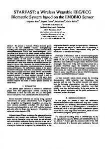
Figure 1: Flow of mean-interval algorithm.
There have been many good algorithms for ECG identification/verification, but none has a simple and practical solution to implement ECG identification/verification on a microprocessor. So we propose one, called the meaninterval ECG verification system. In this verification system a mean-interval (MI), calculated from ten R-R intervals, is stored in advance in the flash memory of a microprocessor. The hardware circuit of the ECG capture uses two contacts methods (left hand and right hand). Our goal is to develop an ECG verification card. The verification algorithm of the system will be detailed in Section 2. The circuit system design is found in Section 3. Three other algorithms compared with our algorithm are shown in Section 4. The comparison experiments between our algorithm and three other algorithms are implemented in Section 5, which also presents the real implementation results for our system. Section 6 states the conclusions.
2. Algorithm Design 2.1. Flow of the Algorithm. The system of the solution combines hardware architecture and a verification algorithm to realise personal verification based on an ECG signal. First the ECG signal is captured by the hardware, then R points are found in the signal, and finally ten R-R intervals are cut from the ECG signal to be averaged into one mean cycle. For one person, in the training stage, the mean cycle is calculated and stored in the flash memory of a microprocessor. In the verifying stage, one R-R interval is captured from the input signal and compared with the stored mean cycle (using the correlation coefficient); if the compared result is greater than 0.85 a successful verification is made; otherwise it fails. The graph of this flow is shown in Figure 1.
Journal of Sensors
3 160
200
140 150
120 100
100
80 60
50
40 0
20 0
−50
−20 −100
0
1000 2000 3000 4000 5000 6000 7000 8000 9000 10000
−40
500
0
(a) Twenty seconds of raw ECG data
×105 14
2000
2500
2.5
10
2
8
Power
Power
1500
×105 3
12
6
1.5 1
4
0.5
2 0
1000
(b) Five seconds of filtered ECG data
0
50
100
150
200
250
300
350
400
450
500
0
0
50
100
Frequency (Hz)
150
200
250
300
350
400
450
500
Frequency (Hz)
(c) Frequency response of the raw ECG data
(d) Frequency response of the filtered ECG data
Figure 2: Preprocessing of the ECG signal.
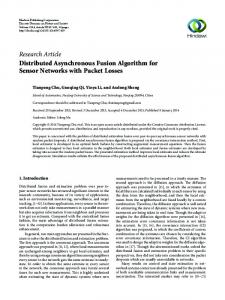
2.2. Preprocessing of the ECG Signal. Various noises [27] exist in the ECG signal, such as the power frequency, baseline drift, hand motion on the contactor, electrode contact noise, and expansion degree of the muscles. These noises are classified as high frequency and low frequency. The high frequency noises are mainly in the power frequency of 50 Hz, and the low frequency ones mainly include the baseline drift of 0.06 Hz caused by breath. Since ECG verification is not doing diagnosis, we do not need to do a radical noise filtering to normalize and regularize ECG signals. From our experiment and experience, some noises might represent the user’s features. Therefore, we only filtered out the noises of high-frequency power and low frequency baseline drift. Raw ECG data sampled from our verification card is shown in Figure 2(a). The sample rate is 500 Hz. Its frequency response is shown in Figure 2(c), and we can see that the power of the 0.06 Hz and 50 Hz frequencies shows a symmetry frequency distribution. A low-pass filter and a highpass filter are applied to filter the two main noises, leaving
a remaining frequency of 1.1 Hz∼30 Hz. Figure 2(b) shows the filtered ECG data, and their corresponding frequency response is shown in Figure 2(d), after removing the noises of 0.6 Hz and 50 Hz. In the microprocessor, we design a 17tap low-pass FIR filter with passband upper frequency of 6 Hz and stopband lower frequency of 30 Hz, and a 17-tap high-pass FIR filter with a corner frequency of 2 Hz. The filter coefficients of the two filters are calculated using the MATLAB Signal Processing Toolbox. After filtering of the raw ECG signal, one next important step in preprocessing is QRS detection or R detection. There are many ways of QRS detection, based on derivative and digital filters, wavelets, neural networks, adaptive filters, and so forth [28]. The Pan-Tompkins real-time QRS detection algorithm [29] is used in our system. The R point (red circle in the figure) detection is shown in Figure 3. The other fiducial points (Q, S, and T) can be detected near the R point. The Q may be the lowest point before the R point within a small range.
4
Journal of Sensors 160
𝛼11 [ 𝛼12 ] [ ] [ . ] [ .. ] [ ] [𝛼 ] [ 1n ] [ . ] ] A=[ [ .. ] [ ] [ 𝛼91 ] [ ] [ 𝛼92 ] [ ] [ .. ] [ . ] [ 𝛼9n ]
140 120 100 80 60 40
𝛽1 [ ] [𝛽 ] [ 2] [ ] [ ] [𝛽 ] [ 3] [. ] ] B=[ [ .. ] [ ] [ ] [ 𝛽7 ] [ ] [ ] [ 𝛽8 ] [ ] [ 𝛽9 ]
50 bpm 60 bpm 70 bpm .. . 110 bpm 120 bpm 130 bpm
20 0
Figure 4: Calculation of the multiple-status.
−20 −40
0
500
1000
1500
2000
2500
Figure 3: R detection of five seconds ECG.
2.3. Mean-Interval Method. We designed an experiment for testing the number of cycles, used to obtain the mean-interval in the ECG verification model, to achieve a good recognition result with a low complexity of calculation. So this test takes 1 to 10 cycles of ECG data into account and is implemented on the MIT-BIH Normal Sinus Rhythm Database, with 18 healthy individuals. In preparing the data for the experimentation stage, 100 cycles are filtered out from every person. There are 60 to 100 heartbeats in one minute in common; in other words there is at least one ECG cycle in one second. Therefore we roughly use this range, 0.6 × sample rate to filter the input ECG signal, and obtain 100 ECG cycles whose length is within the length range of each person. Of course the R point must first be extracted from the ECG data, and then you can measure the length of the R-R interval and decide whether to use it or not (not in the length range). In the mean-interval method there are 𝑛 normal R-R intervals of one person like 𝑆1 , 𝑆2 , 𝑆3 , . . . , 𝑆𝑛 . How to “average” and get the “mean-interval” is as follows. (1) Calculate the average length of the 𝑛 R-R intervals (𝑆 + 𝑆 + 𝑆 + ⋅ ⋅ ⋅ + 𝑆𝑛 ) (1) 𝜇 = 1 2 3 . 𝑛 In (1) |𝑆𝑖 | means the length of the R-R interval 𝑆𝑖 . (2) Stretch every R-R interval to make its length equal to 𝜇, using the 𝑖th R-R interval as an example. If |𝑆𝑖 | > 𝜇, you should compress it, deleting one sample point at 𝜌 intervals: 𝑆 + 1⌋ . (2) 𝜌 = ⌊ 𝑖 (𝑆𝑖 − 𝜇) If 𝜇 > |𝑆𝑖 | you should stretch it, inserting one sample point with a value 𝜑 between 𝑎 and 𝑏 at 𝜌 intervals: (𝑎 + 𝑏) 𝜑= 2 𝑆 𝜌 = ⌊ 𝑖 + 1⌋ . (𝜇 − 𝑆𝑖 )
(3)
Supposing 𝛼 = min(|𝑆1 |, |𝑆2 |, |𝑆3 |, . . . , |𝑆𝑛 |) and 𝛽 = max(|𝑆1 |, |𝑆2 |, |𝑆3 |, . . . , |𝑆𝑛 |), the method of the R-R length filter makes sure that 2𝛼 ≥ 𝛽; in other words there is just one compress or stretch implementation in the second step. (3) Average the 𝑛 normal R-R interval into one “meaninterval” 𝑋 with the length 𝜇: 𝑋𝑖 =
(𝑆1𝑖 + 𝑆2𝑖 + 𝑆3𝑖 + ⋅ ⋅ ⋅ + 𝑆𝑛𝑖 ) . 𝑛
(4)
The 𝑆1𝑖 equals the 𝑖th sample point of the 1st R-R interval, and so on. For ECG verification, using the meaninterval method mentioned above to obtain one averaged RR interval, under a fixed heartbeat rate as the model in the training step, is called single-status MI algorithm which only considers the R-R interval within one certain heartbeat rate. But we know that the heart rate of one person will decrease slowly from 125 bpm to 60 bpm after playing sport. The wave of the ECG is stretched along with the change in the rate of the heartbeat. So we use a multiple-status MI algorithm which considers the R-R intervals of 50∼125 bpm heartbeat rates. Some programs are required to realise this. (1) Consider heartbeat rates from 50∼130 bpm and use 10 bpm to segment them into 9 heartbeat rates (𝐻 = [50, 60, 70, 80, 90, 100, 110, 120, 130]), because there is just a slight change in the ECG for one person whose heartbeat rate wavers within 10 bpm. (2) Capture 𝐴 which contains 𝑛 R-R intervals whose length is nearest to the fixed length of the R-R interval of each heartbeat rate of 𝐻. If the sample rate of the raw data is 𝜌, then the length of the R-R interval of every heartbeat rate of 𝐻 is expressed by Hl = 𝐻 ⋅
𝜌 . 60
(5)
(3) In 𝐴, for every heartbeat rate of 𝐻, the averaged RR interval is calculated from its 𝑛 R-R intervals. This process is shown in Figure 4. The 𝛼𝑖𝑗 presents the 𝑗th R-R interval of 𝐻(𝑖) of one person, and 𝛽𝑖 is the meaninterval of 𝛼𝑖1 , 𝛼𝑖2 , 𝛼𝑖3 , . . . , 𝛼𝑖𝑛 . 𝐵 denotes the multiplestatus of one person for ECG verification.
Journal of Sensors
1
2
5
3
4
Average
5
100
···
1
2
3
4
100
CC1
3
4
5
2
···
100
···
CC3
···
Model 2
Model 1
2
···
Average 1
1
5
···
CC2
CC3
CC1
CC2
Average
Average
M1
M2
100
···
Figure 5: Diagram of starting mean-interval method (SMI).
Figure 6: Diagram of ending mean-interval method (EMI).
2.4. Mean Cycle Model. There are two mean-interval models, starting with the averaging (SMI model) and ending with the mean-interval model (EMI model). In the SMI model, 𝑛 R-R intervals are averaged to obtain one averaged R-R interval (called the mean cycle); then the verification distance between the comparing R-R interval and mean cycle is calculated. In contrast, for the EMI model, the verification distances between the 𝑛 R-R intervals and the comparing R-R interval are first calculated, and then the 𝑛 verification distance values are averaged to obtain the final distance. So there are two questions, one is how many 𝑛 should be set and the other is which averaging model is better for verification. We designed an experiment based on the above 18 × 100 R-R intervals (there are 18 persons with 100 filtered R-R intervals) and used the crossing method. We use the SMI model as an example and use 𝑛 = 3, so 100 R-R intervals will generate 33 mean cycles. Each cycle is compared with the mean cycle, and then a 33 × 100 matrix will be obtained. Figure 5 shows the diagram of the SMI model. In Figure 5 we can see that there are three layers, the first layer and the third layer denote the 100 R-R intervals and the second layer represents the 33 mean cycles (called the model). Through averaging, the first layer becomes the second layer, and then a correlation coefficient value is calculated between each cycle of the third layer and every model of the second layer. Figure 6 shows the diagram of the EMI model. There are four layers in Figure 6, the first layer and second layer denote the one hundred cycles of one person, and every three elements of the third layer, with three values (termed CC1 , CC2 , CC3 ), are the correlation coefficient values between one cycle of the second layer and 𝑛 = 3 cycles of the first layer. The 𝑀𝑖 in the fourth layer is the average value of every three values in the third layer. Suppose that there is a database which contains 𝑀 cycles with the same length 𝐿 of one person. If the starting mean-interval method using 𝑛 R-R intervals as the reference segment is applied to this database, (6) and (7) can describe the program of the experiment method of the algorithm. In these formulas, 𝑑[𝑖] represents the 𝑖th R-R interval ECG data of one person, and 𝑑[𝑖][𝑗] indicates the 𝑗th value of the 𝑖th R-R interval. That is, an averaged value is calculated from the 𝑛 corresponding points of the 𝑛 intervals chosen as the reference segment, before averaging, and the chosen 𝑛 R-R
intervals must be interpolated into the same length 𝐿; (6) shows this function. So 𝑀 cycles will have ⌊𝑀/𝑛⌋ reference cycles and the mean-interval (MI) as a model that comes from it. In (7) there is a correlation coefficient between 𝑀 cycles and the ⌊𝑀/𝑛⌋ mean-intervals which come from the mean of the ⌊𝑀/𝑛⌋ reference segments. Finally, calculate the mean value of all correlation coefficient values, named the distance: ∑𝑛𝑘=1 𝑑 [(𝑖 − 1) × 𝑛 + 𝑘] [𝑗] 𝑛 𝑗=1
(6)
∑⌊𝑀/𝑛⌋ ∑𝑀 𝑖=1 𝑗=1 corrcoef (𝑑 [𝑗] , mean cycle [𝑖])
(7)
𝐿
mean cycle [𝑖] [𝑗] = ∑ distance =
⌊𝑀/𝑛⌋ × 𝑀
.
The function corrcoef (correlation coefficient representing the similar relationship between two waves) is expressed by 𝑟𝑋𝑌 =
∑𝑁 𝑖=1 (𝑋𝑖 − 𝑋) (𝑌𝑖 − 𝑌) 2
𝑁 √ ∑𝑁 𝑖=1 (𝑋𝑖 − 𝑋) ∑𝑖=1 (𝑌𝑖 − 𝑌)
2
.
(8)
For 18 individuals we obtain a 18 × 33 × 100 value matrix, by averaging the 33 × 100 submatrix and obtaining 18 mean distances of self-comparison for every person, such as the comparison of one individual’s data against their remaining data; it takes the 𝑛 (= 1∼10) cycles as the reference segment into account; we finally obtain a 10 × 18 distance matrix. The mean values of the 18 distances are shown in Figures 7 and 8 within SMI and EMI methods. The horizontal axis denotes the cycle, and the vertical axis denotes the distance generated by (2). In Figure 7, as 𝑛 increases the value of the mean correlation coefficient (MIC) also increases. In particular, when the cycle number is greater than 2, the value of the mean correlation coefficient is higher than 0.9. But in Figure 8, when the cycle number increases the trend of the value of MIC is down; obviously, the MIC does not exceed 0.9. From the above comparison between Figures 7 and 8, it can be seen that the starting mean-interval model (SMI
6
Journal of Sensors Antenna
Reset button
Clock
0.92 0.91
ZigBee
Touch spot I
MSP430
Instrument amplifier
Antenna
0.93 Battery
0.89
ZigBee
0.88 0.87 1
2
3
4
5
6
7
8
9
Clock
0.9 Clock
Mean correlation coefficient (MCC)
0.94
Electric relay
10
Cycle number (n)
Figure 7: Comparison result of starting mean-interval method.
Mean correlation coefficient (MCC)
Battery
Touch spot II
Door
0.94 0.93 0.92 0.91 0.9 0.89 0.88 0.87 1
2
3
4
5
6
7
8
9
10
Cycle number (n)
Figure 9: Hardware architecture of ECG verification system.
Figure 8: Comparison result of ending mean-interval method.
model) is better than the ending mean-interval model (EMI model) in the self-comparison; in another test the results from the comparison of others are the same as those for self-comparison. From Figure 7 we can see that there is an acceptable verification result for self-comparison when 𝑛 is above 3.
3. Circuit System Design The hardware architecture of this system contains two parts, a verification card and door control. In Figure 9, the left part of the top section is the verification part; there are twohand contacting dots on the card for the introduction of Lead I of the ECG. Its overall size is slightly smaller than that of a common bank card; and the other side of the top section is the door control part. This includes the controller which is a ZigBee module, just for receiving the signal and a door whose lock is connected to the controller. In the lower section of Figure 9 there are two images corresponding to the above section. As a connection interface, the wireless ZigBee module provides simple, low data traffic, but a security bridge is required between the verification card part and the door control part. 3.1. Verification Card Part. The main function of the verification part is to capture the ECG signal from the human, filter and extract features for verification, and perform verification and the translation of the verification results by the ZigBee module.
In the verification part, the MSP430 is chosen as the microprocessor, since it has an ultra-low power consumption feature and internal operational amplifier which must be used in the amplification of the ECG signal. Combined with the ZigBee module, a network is created between the ECG verification card and the door connected to the ZigBee module for receiving the control command. An amplifier is used for accurately capturing the ECG signal from two hands and can be disabled by the microprocessor, further saving energy. How Is the Electrocardiogram Signal Captured? There are many hardware circuits designed for the capture of ECG signals. The common medical measurement of ECG signal includes 12-leads and 5-leads. Another specialist method is the 1-lead; it is a subset of the above two methods, capturing the ECG signal from the left and right hands. We can see that the 1-lead is sufficient enough [13] and convenient for ECG verification. So we chose this measurement method for our solution. Two steps must be taken for the 1-lead method: the first step captures the voltage difference which is the weak electrical signal from the heart and the second step amplifies that weak front signal hundreds of times for the A/D function module. Figure 10 shows the relationship of these function blocks. A low-pass filter or high-pass filter circuit can be set between the “OP” block and “A/D” block to filter the noise. We implement this in the microprocessor by incorporating a software filter. In the first step, in order to capture the ECG signal availably and accurately, the circuit is designed by considering some important factors:
Journal of Sensors
7
Step 1
+
V1
Step 2
Electrodes
Preamplifier
− Operational amplifier
R3
R1 DAC
+ Rg
Figure 10: Functional blocks of ECG measurement.
(1) The real ECG signal is an mV signal, so it must be magnified about 1000 times. A high gain circuit is required. (2) The ECG signal is translated from the heart to the hand, and the body has high resistance. To overcome this problem the circuit should have a high input impedance feature.
40
In the second step, we know that the weak ECG signal should be magnified by about 1000 times and magnify 5 times in the front-end amplifier, so, in current step, further 200 times are required. The operational amplifier is used to achieve this. Because the MSP430 microprocessor itself has several operational amplifiers, the second step is implemented within it. And the final amplified ECG signal is input into its A/D function module in order to sample data. 3.2. Door Control Part. The door control part, with the ZigBee module, receives the control command from the verification part and controls the door obeying the command. The command set just contains the opening and closing of the door lock. The connection security between the verification card part and door control part is mature and the hardware encryption technology of the ZigBee is provided in their products.
−
R4
R5
140
(4) The heart rate of a human is 60∼100 times per minute, and the frequency of the ECG signal mainly concentrates around 0.25∼35 Hz. The low-pass filter can be operated by the hardware circuit or software filter. In our system the low-pass filter is implemented by the software.
(9)
Vout
160
120
𝑅𝑓 2𝑅1 )( ). 𝑅𝑔 𝑅3
A3
Figure 11: Typical circuit of instrument amplifier.
(3) Because there are various noises, especially commonmode interference, coming from the movement of the hand, temperature, and interference from other nearby electrical equipment which influences the measurement of the ECG.
Taking these factors into account, the instrument amplifier with a high CMMR (should >80 dB) is chosen as the front-end amplifier. A typical circuit graph of the instrument amplifier is shown in Figure 11. Its gain can be calculated by (9). Here 𝐺 = 5,
A2
V2
−
R2
+
𝐺 = (1 +
Rf
A1
100 80 60
20 0
−20 −40
0
500
1000
1500
2000
2500
Figure 12: Difference of 𝑛 (cycle number) and 𝑀 (sample cycle number), 𝑀 = 5 and 𝑛 = 6.
4. Compared Algorithms Four ECG verification algorithms are compared in this experiment with the same database and comparison method. The four verification algorithms are listed below. 4.1. Mean-Interval. From Section 2, we know that the SMI model is better than the EMI model, and while the cycle is increased, the comparison of the results for self-comparison slowly improves. So we use the SMI model and choose 𝑛 = 10 to achieve person verification. In fact we use sample cycle (𝑀) to improve 𝑛 for practical applications. The value of sample cycle is fixed, but 𝑛 is based on the number of real R-R intervals existing in the current 𝑀 cycles. That is, 𝑛 RR intervals of 𝑀 cycles of ECG data are averaged to one mean cycle, as the reference cycle. For equality we set 𝑀 = 10 (every 𝑀 sample cycles) and 𝑛 R-R intervals from each sample cycles. Supposing a sample rate of 500 Hz and 𝑀 = 5, Figure 12 shows the result of 𝑛. Because 6 R-R intervals exist within the 2500 (= 𝑀 × sample rate) sample points, 𝑛 = 6. 4.2. Wavelet. Wavelet analysis or wavelet transformation is the finite or rapid attenuation of oscillation waveform signals,
8
Journal of Sensors 140 120
intervals by the segmentation method. At last the verification bases on the Euclidean distance as the distance formula shown in
R-R interval
100
𝑛
80 85
60
2
𝑑 (𝑋, 𝑌) = √ ∑ (𝑋𝑖 − 𝑌𝑖 ) .
43
(13)
𝑖=1
40 20 0
−20 −40
0
50
100
150
200
250
300
350
400
Figure 13: Segmentation method in R-R interval.
which is called the mother wavelet. The waveform is zooming and panning to match the input signal. Wavelet transform has good location on the timeline and fast calculation. There are many different wavelet transforms, such as Continuous Wavelet Transforms (CWT), Discrete Wavelet Transforms (DWT), Fast Wavelet Transform (FWT), and Wavelet Packets Decomposition (WPD), and each of them is suited to different applications. The mother wavelet 𝜓𝑗,𝑘 (𝑡) expansion and transformation can be expressed as in formula 1 𝑡−𝜏 [ 𝜓𝑗,𝑘 (𝑡) = ]. √𝑘 𝑘
(10)
In (10), 𝑘 is a scale coefficient and 𝜏 defines the shift coefficient. The wavelet coefficient equation and inverse transform formulae are as follows: 𝐶𝑗,𝑘 = ∫
∞
−∞
𝑓 (𝑡) 𝜓𝑗,𝑘 (𝑡) 𝑑𝑡
(11)
4.3. Waveform. Waveform-based algorithms are a representation of the ECG waveform feature, and these features are used for verification. Since a statistical approach is used to obtain these waveform features, sometimes they are also called statistical algorithms in other literatures. Their general operational procedure is as follows. Firstly, after ECG-collection high- and low-pass filtering are used for early preprocessing, then various methods are used to extract the characteristic points of these waveforms, such as points P, Q, R, S, and T among the ECG signals. On the basis of their features, relative representations are extracted to compose proper individual features, such as amplitude, duration, and slope and area. The extraction of feature points and values is shown in Figure 14. There are four kinds of verification feature: (1) Amplitude: PQ, RQ, TQ, RT, PS, RP, TS, RS, PT, QS. (2) Duration: QS, PR, QR, ST, QT. (3) Slope: RS, ST and QR. (4) Area: QRS triangle area. After obtaining some waveform features for the individual differences, a similarity algorithm is applied to evaluate the differences between two individuals. 4.4. Reduced Binary Pattern. This algorithm uses the frequency and rank order statistics of the underlying pattern of the input ECG data [30]. Such data exists in serial 𝑆 = {𝑠1 , 𝑠2 , 𝑠3 , . . . , 𝑠𝑛 }, consider
𝑓 (𝑡) = ∑ 𝐶𝑗,𝑘 𝜓𝑗,𝑘 . The approach of achieving ECG verification uses Wavelet transform processing [16] for our comparison and first performs R detection for ECG Wavelet analysis to obtain each R-R cardiac interval. After that it performs a cutting method on the R-R intervals to conduct R-R width adjustment to fit a single new cycle with 128 points. The cutting method for a R-R interval cuts 85 points from the beginning of the interval and 43 points from the end of the interval. This is shown in Figure 13. Then 4 R-R intervals are cut into four new cycles with 512 points. Finally, it applies the Wavelet transform for multiple layers processing to obtain the Wavelet coefficients, which is a new sequence of wavelet coefficients as given in 𝑋 = 𝑎𝑛 + 𝑑𝑛 + 𝑑𝑛−1 + ⋅ ⋅ ⋅ + 𝑑1 .
(12)
If 𝑋 and 𝑌 are two different Wavelet coefficients, verification can be estimated by a suitable distance formula 𝑑(𝑋 , 𝑌 ). In practice, 10 layers’ processing of the Wavelet transform is implemented on 512 sample points, sampled from 4 R-R
{1 𝑋𝑖 = { 0 {
𝑠𝑖+1 > 𝑠𝑖 𝑠𝑖+1 ≤ 𝑠𝑖 .
(14)
So, through (14), 𝑆 is translated to 𝑋 containing 0/1 bit, and 𝑛 − 1 in length. From the first number in 𝑋, 𝑚 sequential numbers compose an 𝑚-bit-word number. Then by shifting one by one, finally a new serial 𝑌 of 𝑛 − 𝑚 in length is created from 𝑋. And the value of the number in 𝑌 is between 1∼ 2𝑚−1 . Then the frequency and rank order statistic method is implemented on 𝑌.
5. Experiment We have introduced four algorithms used for verification in Section 4. In the current section an experiment is designed to conduct a comparison between the four algorithms. For equality, a cross comparison method is applied to the experiments. Meanwhile, for completeness, two public MIT-BIH ECG databases, MIT-BIH Arrhythmia and Normal Database, are adopted as input data for the experiments.
Journal of Sensors
9 PR duration
R
RQ slope RP amplitude
RS slope RT amplitude
RS amplitude
RQ amplitude
TP amplitude
T
P
PQ amplitude
QRS triangle area
PS amplitude Q
QR duration
TS amplitude
ST slope
TQ amplitude
QS amplitude QS duration
S
ST duration QT
duration
Figure 14: Extracted features from one cycle.
5.1. Experiment Data. Two ECG databases are used in our experiment: (1) MIT-BIH Arrhythmia Database [31]: the BIH Arrhythmia Laboratory was built between 1975 and 1979. The data selected is 48 groups, within two-lead ECG data recordings of half an hour, a total of up to 24 hours of ECG data. It contains 47 personal ECG data (201 groups and 202 groups of ECG data coming from the same person), the subjects are 25 men with ages ranging from 32 to 89 years and 22 women with ages from 23 to 89 years, in which close to 60% of the 47 subjects are hospitalised patients. (2) MIT-BIH Normal Sinus Rhythm Database [32]: this database contains 18 long-term ECG recordings; these people are found to have no significant arrhythmias. The subjects include 5 men, aged 26 to 45, and 13 women, aged 20 to 50. The ECG signal sampling rate is 128 Hz. The data storage format for 12 bits of binary representation is known as “212” format, in which there is a sign bit. From the above description we know there are 65 subjects. According to the data requirement of the experimental method, eight groups, containing ten sample cycles (10 seconds) of data, are cut from each person. Use 𝑆𝑖𝑗 (1 ≤ 𝑖 ≤ 65, 1 ≤ 𝑗 ≤ 8) to represent the 𝑖th group of ECG data from the 𝑗th person. 5.2. Experimental Method. This experiment uses the cross comparison method, if making a comparison with a cross
self-comparison should be made between the 8 groups of data from one person; if comparing with others, conduct a mutual comparison between the 8 groups of data from one person and the 8 groups from the other person. We use the average distance to represent the final distance of the two individuals, so a division will be operated after an addition of the 64 distance values. The experimental method can be described as [14] 𝑚𝑝 𝑚𝑞
1 𝐷 (𝑆𝑝 , 𝑆𝑞 ) = ∑ ∑ 𝑑 (𝑆𝑝𝑖 , 𝑆𝑞𝑗 ) . 𝑚𝑝 ⋅ 𝑚𝑞 𝑖=1 𝑗=1
(15)
In formula (9), 𝑆𝑝𝑖 and 𝑆𝑞𝑗 denote, respectively, the 𝑖th, 𝑗th groups of data from 𝑝th and 𝑞th individuals (1 ≤ 𝑝, 𝑞 ≤ 65 and 1 ≤ 𝑖, 𝑗 ≤ 8). 𝐷(𝑆𝑝 , 𝑆𝑞 ) calculates the average distance between the 𝑝th and 𝑞th person. Furthermore, the 𝑑(𝑆𝑝𝑖 , 𝑆𝑞𝑗 ) works as the verification distance between the two groups of ECG dates by the verification algorithms. 5.3. Experiment Result. We apply the four verification algorithms and the experimental method to the two MITBIH databases mentioned above. The mean-interval (MI) algorithm, for example, is implemented on the MIT-BIH Arrhythmia Database, for which a 47 × 47 results’ table is generated; the comparison results of self-comparison lie on the diagonal line of the table, and the other cells of the table identify the value of comparison with others. A section (8 persons) of the results table is shown in Table 1. From Table 1 we can see that the value of the numbers lying on the diagonal is larger than the others in the same
10
Journal of Sensors Table 1: Comparison results of 8 people.
Number Data file name 1 2 3 4 5 6 7 8
100.dat 101.dat 102.dat 103.dat 104.dat 105.dat 106.dat 107.dat
1 100.dat
2 101.dat
3 102.dat
4 103.dat
5 104.dat
6 105.dat
7 106.dat
8 107.dat
0.995739 0.042074 0.021244 0.070864 −0.21247 −0.00549 0.043187 0.009627
0.040959 0.991551 −0.07092 0.049626 −0.06998 −0.06269 0.066068 0.149587
0.025142 −0.09187 0.972407 −0.14143 0.009141 0.060439 −0.05331 −0.04291
0.091299 0.05923 −0.15169 0.99771 −0.09159 0.0534 0.058882 0.026265
−0.15982 −0.04554 −0.0293 −0.08191 0.94894 0.084114 −0.04081 −0.06453
0.011561 −0.0517 0.065066 0.07528 0.041129 0.992397 0.05672 −0.04472
0.014194 0.016271 −0.03552 0.046861 0.006288 0.034648 0.952014 −0.04213
0.024176 0.120851 −0.02223 0.015396 −0.05862 −0.06725 −0.05169 0.984541
Table 2: The success rate of the four algorithms. Success rate 95.7447% 95.656% 99.3351% 100%
row of the table, and most of them are close to 0.99. It also proves that one person has a high similarity to themselves. In contrast, the value of the comparison with others is very small, some even negative, denoting a negative relationship. The larger the gap between the values of the diagonal and the others value, the simpler it is to distinguish self-comparison from the others. Suppose that there is an error, when a value lying on the diagonal is smaller than the others that lie on the same row. Using this rule, we can statistically determine the success rate of the four algorithms. Table 2 shows the success rate of the four algorithms. Table 2 shows that the success rates of all four algorithms that are greater than 95%, and the mean-interval (MI) algorithm has the best success rate of 100% of all four algorithms. So it is a useful and effective method for personal verification based on ECG. But we must consider that the mean-interval algorithm using the correlation coefficient, which simply evaluates the similarity or the waviness of two waves and disregards the specific values. This weak point will introduce some issues of safety. Even with that shortcoming, the MI algorithm is sufficient for our verification system. 5.4. Sport Issue. We know that there are big changes in the heart rate after the sport. This will seriously disturb the person’s verification based on their ECG signal, so the sport problem is more important than the long-term problem in ECG verification. Figure 15 shows the electrocardiograms of one person with different heart rates. There are two main changes taking place; one is that the baseline seriously shifts due to the deeper breaths taken after sport; the other is that the heart rate of the person becomes higher due to accelerated heart action. From the measurement of the ECG after sport, the heart rate waves near a special number, like 60 or 55, in the resting
MI algorithm Single-state Multiple-state
FR 0.1407 0.0915 120
FA 0.2573 0.0750 110 90 80 100
70
Average 0.398 0.1665 60 bpm
50
Amplitude
Algorithm Wavelet RBP Waveform Mean-interval (MI)
Table 3: Sport verification results.
1
51 101 151 201 251 301 351 401 451 501 551 Time
Figure 15: R-R intervals of different heartbeat rates of one person.
state; and when you take exercise within 3 minutes the heart rate quickly increases to 100; within 5 minutes or more the heart rate slowly begins increasing to 120, finally it will stand near 125. There are 10 individuals, including 1 female and 9 males, in the sport ECG database. The FreeScale ECG board is used to measure all subjects for five minutes in the resting state and five minutes after his/her sport. To conquer the issue of the sport heart rate, we use the multiple-state MI algorithm. We use resting and sport’s data to train the system and then test it with the only the sport data. For comparison, the single-state MI algorithm is also implemented on this sport ECG database. Table 3 shows the verification results of the two algorithms. The multiple-state MI has much better performance than the original singlestate algorithms.
6. Conclusions We have proposed a new algorithm and mobile circuit system for ECG verification. An effective verification algorithm is implemented on this system providing a feasible application. The hardware is designed for consideration of low power consumption and the convenience of a wireless network. We designed an operational solution to overcome the issue of ECG verification. In the evaluation, the accuracy of the MI
Journal of Sensors algorithm is better than in previous algorithms. Next, we also proposed a multiple-state MI algorithm to handle the issue of the heart rate after sport. In the evaluation, it truly presents better performance than the original MI, with 23.15% for sport testing. Finally, if the sport issue can be resolved for ECG verification, it might also be a feasible tool for biometric verification systems.
Competing Interests The authors have no competing interests to declare.
Acknowledgments The work described in this paper was partially supported by a grant from the Research Grants Council of the Hong Kong Special Administrative Region, China (PolyU 152108/15E). This work is also partially supported by the Research Committee and the Department of ISE of the Hong Kong Polytechnic University (G-UB97), the Department of Computer Science, Shenzhen Graduate School of Harbin Institute of Technology, and Shenzhen Technology Project (JCY2015051706567).
References [1] N. Maglaveras, T. Stamkopoulos, K. Diamantaras, C. Pappas, and M. Strintzis, “ECG pattern recognition and classification using non-linear transformations and neural networks: A review,” International Journal of Medical Informatics, vol. 52, no. 1-3, pp. 191–208, 1998. [2] H. Zhang and L.-Q. Zhang, “ECG analysis based on PCA and support vector machines,” in Proceedings of the International Conference on Neural Networks and Brain Proceedings (ICNNB ’05), pp. 743–747, Beijing, China, October 2005. [3] H. Blackburn, A. Keys, E. Simonson, P. Rautaharju, and S. Punsar, “The electrocardiogram in population studies. A classification system,” Circulation, vol. 21, pp. 1160–1175, 1960. [4] D. P. Golden, R. A. Wolthuis, and G. W. Hoffler, “A spectral analysis of the normal resting electrocardiogram,” IEEE Transactions on Biomedical Engineering, vol. 20, no. 5, pp. 366–372, 1973. [5] M. Kobayashi and T. Musha, “1/f Fluctuation of heartbeat period,” IEEE Transactions on Biomedical Engineering, vol. 29, no. 6, pp. 456–457, 1982. [6] N. V. Thakor, J. G. Webster, and W. J. Tompkins, “Estimation of QRS complex power spectra for design of a QRS filter,” IEEE Transactions on Biomedical Engineering, vol. 31, no. 11, pp. 702– 706, 1984. [7] N. V. Thakor and Y.-S. Zhu, “Applications of adaptive filtering to ECG analysis: noise cancellation and arrhythmia detection,” IEEE Transactions on Biomedical Engineering, vol. 38, no. 8, pp. 785–794, 1991. [8] Y. H. Hu, W. J. Tompkins, and J. L. Urrusti, “Applications of artificial neural networks for ECG signal detection and classification,” Journal of Electrocardiology, vol. 26, pp. 66–73, 1993. [9] V. F. Kravchenko and A. Y. Popov, “Digital filters in human ECG processing and analysis,” Measurement Techniques, vol. 37, no. 2, pp. 220–223, 1994.
11 [10] G. G. Berntson, J. Thomas Bigger Jr., D. L. Eckberg et al., “Heart rate variability: origins, methods, and interpretive caveats,” Psychophysiology, vol. 34, no. 6, pp. 623–648, 1997. [11] I. J. Rampil, “A primer for EEG signal processing in anesthesia,” Anesthesiology, vol. 89, no. 4, pp. 980–1002, 1998. [12] V. X. Afonso, W. J. Tompkins, T. Q. Nguyen, and S. Luo, “ECG beat detection using filter banks,” IEEE Transactions on Biomedical Engineering, vol. 46, no. 2, pp. 192–202, 1999. [13] L. Biel, O. Pettersson, L. Philipson, and P. Wide, “ECG analysis: a new approach in human identification,” IEEE Transactions on Instrumentation and Measurement, vol. 50, no. 3, pp. 808–812, 2001. [14] T. W. Shen, W. J. Tompkins, and Y. H. Hu, “Implementation of a one-lead ECG human identification system on a normal population,” Journal of Engineering and Computer Innovations, vol. 2, pp. 12–21, 2011. [15] P. Sasikala and R. S. D. Wahidabanu, “Identification of individuals using electrocardiogram,” International Journal of Computer Science and Network Security, vol. 10, pp. 147–153, 2010. [16] A. D. C. Chan, M. M. Hamdy, A. Badre, and V. Badee, “Wavelet distance measure for person identification using electrocardiograms,” IEEE Transactions on Instrumentation and Measurement, vol. 57, no. 2, pp. 248–253, 2008. [17] F. Sufi, I. Khalil, and I. Habib, “Polynomial distance measurement for ECG based biometric authentication,” Security and Communication Networks, vol. 3, no. 4, pp. 303–319, 2010. [18] C. Ye, M. T. Coimbra, and B. V. K. V. Kumar, “Investigation of human identification using two-lead electrocardiogram (ECG) signals,” in Proceedings of the 4th IEEE International Conference on Biometrics: Theory, Applications and Systems (BTAS ’10), pp. 1–8, Washington, DC, USA, September 2010. [19] Z. D. Zhao and L. Yang, “ECG identification based on matching pursuit,” in Proceedings of the 4th International Conference on Biomedical Engineering and Informatics (BMEI ’11), vol. 2, pp. 721–724, Shanghai, China, October 2011. [20] T. W. Shen, W. J. Tompkins, and Y. H. Hu, “One-lead ECG for identity verification,” in Proceedings of the 2nd Joint EMBS/BMES Conference: Engineering in Medicine and Biology—24th Annual Conference and the Annual Fall Meeting of the Biomedical Engineering Society, vol. 1, pp. 62–63, Houston, Tex, USA, October 2002. [21] A. C.-C. Yang, S.-S. Hseu, H.-W. Yien, A. L. Goldberger, and C.-K. Peng, “Linguistic analysis of the human heartbeat using frequency and rank order statistics,” Physical Review Letters, vol. 90, no. 10, 2003. [22] C. Hegde, H. R. Prabhu, D. S. Sagar, P. Deepa Shenoy, K. R. Venugopal, and L. M. Patnaik, “Statistical analysis for human authentication using ECG waves,” in Information Intelligence, Systems, Technology and Management, vol. 141 of Communications in Computer and Information Science, pp. 287–298, 2011. [23] S. A. Israel, J. M. Irvine, A. Cheng, M. D. Wiederhold, and B. K. Wiederhold, “ECG to identify individuals,” Pattern Recognition, vol. 38, no. 1, pp. 133–142, 2005. [24] J. G. Webster, Medical Instrumentation: Application and Design, John Wiley & Sons, Philadelphia, Pa, USA, 1997. [25] A. Aleksandrowicz and S. Leonhardt, “Wireless and noncontact ECG measurement system—the ‘Aachen SmartChair’,” Acta Polytechnica, vol. 47, no. 4-5, pp. 68–71, 2007. [26] Y. G. Lim, K. K. Kim, and K. S. Park, “ECG measurement on a chair without conductive contact,” IEEE Transactions on Biomedical Engineering, vol. 53, no. 5, pp. 956–959, 2006.
12 [27] G. M. Friesen, T. C. Jannett, M. A. Jadallah, S. L. Yates, S. R. Quint, and H. T. Nagle, “A comparison of the noise sensitivity of nine QRS detection algorithms,” IEEE Transactions on Biomedical Engineering, vol. 37, no. 1, pp. 85–98, 1990. [28] B.-U. Kohler, C. Hennig, and R. Orglmeister, “The principles of software QRS detection,” IEEE Engineering in Medicine and Biology Magazine, vol. 21, no. 1, pp. 42–57, 2002. [29] J. Pan and W. J. Tompkins, “A real-time QRS detection algorithm,” IEEE Transactions on Biomedical Engineering, vol. 32, no. 3, pp. 230–236, 1985. [30] F. Zeng, K.-K. Tseng, H.-N. Huang, S.-Y. Tu, and J.-S. Pan, “A new statistical-based algorithm for ECG identification,” in Proceedings of the 8th International Conference on Intelligent Information Hiding and Multimedia Signal Processing (IIH-MSP ’12), pp. 301–304, IEEE, Piraeus, Greece, July 2012. [31] A. L. Goldberger, L. A. N. Amaral, L. Glass et al., “PhysioBank, PhysioToolkit, and PhysioNet: components of a new research resource for complex physiologic signals,” Circulation, vol. 101, no. 23, pp. e215–e220, 2000. [32] G. B. Moody and R. G. Mark, “The impact of the MIT-BIH arrhythmia database,” IEEE Engineering in Medicine and Biology Magazine, vol. 20, no. 3, pp. 45–50, 2001.
Journal of Sensors
International Journal of
Rotating Machinery
Engineering Journal of
Hindawi Publishing Corporation http://www.hindawi.com
Volume 2014
The Scientific World Journal Hindawi Publishing Corporation http://www.hindawi.com
Volume 2014
International Journal of
Distributed Sensor Networks
Journal of
Sensors Hindawi Publishing Corporation http://www.hindawi.com
Volume 2014
Hindawi Publishing Corporation http://www.hindawi.com
Volume 2014
Hindawi Publishing Corporation http://www.hindawi.com
Volume 2014
Journal of
Control Science and Engineering
Advances in
Civil Engineering Hindawi Publishing Corporation http://www.hindawi.com
Hindawi Publishing Corporation http://www.hindawi.com
Volume 2014
Volume 2014
Submit your manuscripts at http://www.hindawi.com Journal of
Journal of
Electrical and Computer Engineering
Robotics Hindawi Publishing Corporation http://www.hindawi.com
Hindawi Publishing Corporation http://www.hindawi.com
Volume 2014
Volume 2014
VLSI Design Advances in OptoElectronics
International Journal of
Navigation and Observation Hindawi Publishing Corporation http://www.hindawi.com
Volume 2014
Hindawi Publishing Corporation http://www.hindawi.com
Hindawi Publishing Corporation http://www.hindawi.com
Chemical Engineering Hindawi Publishing Corporation http://www.hindawi.com
Volume 2014
Volume 2014
Active and Passive Electronic Components
Antennas and Propagation Hindawi Publishing Corporation http://www.hindawi.com
Aerospace Engineering
Hindawi Publishing Corporation http://www.hindawi.com
Volume 2014
Hindawi Publishing Corporation http://www.hindawi.com
Volume 2014
Volume 2014
International Journal of
International Journal of
International Journal of
Modelling & Simulation in Engineering
Volume 2014
Hindawi Publishing Corporation http://www.hindawi.com
Volume 2014
Shock and Vibration Hindawi Publishing Corporation http://www.hindawi.com
Volume 2014
Advances in
Acoustics and Vibration Hindawi Publishing Corporation http://www.hindawi.com
Volume 2014