LESTER H. FINK, SENIOR MEMBER, IEEE, HARRY G. KWATNY, AND JOHN P. McDONALD. Abstract-The valve-point loading logic described in this paper is.
805
IEEE TRANSACTIONS ON POWER APPARATUS AND SYSTEMS, VOL. PAS-88, NO. 6, JUNE 1969
Economic Dispatch of Generation Valve-Point Loading LESTER H. FINK,
SENIOR MEMBER, IEEE,
HARRY G. KWATNY,
Abstract-The valve-point loading logic described in this paper is intended to meet at any time in the most economical fashion a generation commitment. This objective is approached by insuring that as great a portion of the load as practicable will be carried by units loaded to valve points, that the remainder of the load will be carried by units reserved for regulation, and that in both categories the assignments will be made to those units which can provide the requisite capacity at the lowest cost.
INTRODUCTION ECONOMIC dispatch involves the implementation of some solution to the problem of apportioning a given total load between a plurality of generating sources in such a way as to minimize the costs of generation and transmission. The classical solution, which says that costs are minimal when the incremental costs of generation at the several sources are equal, is based on monotonically increasing incremental cost curves. This assumption is not everywhere valid because of the throttling losses incurred when steam chest valves are barely open. These losses introduce negative slopes into the incremental cost curves. The basic desirability of and justification for operating at the local minima of the curves, referred to as valve-point loading, has been discussed for many years [1], [2]. It is the intent of this paper to outline the logic behind and the conceptual development of a central control algorithm for Philadelphia Electric Company's automatically controlled generation, which has been developed for implementing valve-point loading. However, before proceeding, it will be helpful to describe briefly the operational relationship of Philadelphia Electric Company to the Pennsylvania-New Jersey-Maryland Interconnection (PJM) of which it is a member. Unlike other interconnections, PJM from its inception has sought to achieve maximum common economy by operating as a single control area with free-flowing internal ties and a common running cost [3]. Actual interchange of energy among members is recorded and accounted for after-the-fact on an hourly basis. Since PJM thus operates on a common composite incremental cost curve, the basic assumption on which the present logic is based, and which is logically prior to a choice between conventional and valve-point loading, is that the basic commitment of Philadelphia Electric Company, as well as of other members of PJM, to the Interconnection is to provide a previously, implicitly agreed upon amount of generation (megawatts) at any given incremental cost, to which is added responsibility for respondinig to a given fraction of the PJM area requirement signal (AR) up to a given limit. Within the confines of this Paper 69 TP 112-PWR, recommended and approved by the Power System Engineering Committee of the IEEE Power Group for presentation at the IEEE Winter Power Meeting, New York, N.Y., January 26-31, 1969. Manuscript submitted September 12, 1968; made available for printing December 13, 1968. L. H. Fink and J. P. McDonald are with the Philadelphia Electric Company, Philadelphia, Pa. H. G. Kwatny is with Drexel Institute of Technology, Philadelphia, Pa.
AND
via
JOHN P. McDONALD
commitment, it is Philadelphia Electric Company's responsibility to provide this amount of generation in the most economic fashion. In other words, if through some oversight or error there should be a discrepancy between the individual incremental cost curves making up the composite curve being used by the Interconnection office and the actual amount of generation which can be provided at a given cost by any one company, the governing responsibility is to provide the amount of generation implicit in the cost curve that has been supplied to the Interconnection. This priority is a necessary, though not sufficient, condition for satisfactory Interconnection operation. It is the obligation of the member companies to keep the Interconnection office continually informed of the prevailing relationship between available generation and incremental cost in order to avoid any conflict such as noted above. Given this commitment, thermodynamic considerations indicate that a given load can be supplied most economically by operating as many units as possible at valve points. It is obvious, however, that valve-point loading can supply generation only in discrete blocks and is inherently unsuited for matching generation to a continuously varying load. This means that a certain amount of capacity must be withheld from valve-point operation in order that it might be operated in a continuously varying manner so as to supply the difference between the valve-point loaded capacity and the continuously varying load which must be satisfied. This consideration reveals the basic nature of regulating capacity and at least implicitly indicates the considerations that must be met in establishing the magnitude and responsiveness of regulating capacity. One very basic requirement for successful implementation of a valve-point loading regime that has not been mentioned so far is that the amount of regulating capacity necessary to take up the difference between block-loaded generation and actual load is a function, among other things, of the amount of time required to pick up or drop one or more blocks of generation. Furthermore, some minimum amount of time, say 10 minutes, must be provided during which a unit remains at a given valve position without a reversal of load, else that unit will not be valve-point loaded, but will in effect have been treated as though it were regulating. These two considerations mean that successful operation of valve-point loading requires some amount of foreknowledge of generation dispatch and therefore of load trend. We believe that failure to recognize this has been the basic weakness of past attempts at valve-point loading by other utilities [4]. The present program is predicated upon the use of a predictive filter designed to satisfy this requirement. The filter will be applied to the incremental cost signal received from the Interconnection, and the predicted cost signal will then be converted to the corresponding megawatts. (It should be noted that if megawatt data are available, the predictor can be applied directly to megawatts.) The basic use of the filter output will be to classify the prevailing load trend as being certainly increasing, certainly decreasing, or essentially steady state. The judgment based on this classification then will determine the specific sequence of logical steps which
806
IEEE TRANSACTIONS ON POWER APPARATUS AND SYSTEMS, JUNE
will be used in arriving at a set of dispatch signals. Moreover, an extremely useful by-product of the availability of a near term load forecast will be a forewarning to operators of actions which they must take in preparing units to permit operation in higher or lower load ranges. If the operator can accomplish these changes in time (15-20 minutes), it will provide smooth transfer from one load range to another. A necesssary characteristic of statistical prediction is that it is provided only within certain confidence limits. The amount of regulating capacity R necessary for successful operation of the type of program under discussion is thus a function, not only of Philadelphia Electric Company's commitment to PJM (1 percent of system capacity), but also of the width of the confidence interval in the prediction. For example, if the confidence interval of the prediction is + 5 MW, the currently required regulating capacity should include 5 MW to cover uncertainty in prediction. Thus, R is a dynamic quantity which constantly reflects system conditions. Sufficient regulating capacity must be available to assure that the difference between block-loaded generation and actual load can be met within the duration of the forecast. In order to put this algorithm in the context of the overall dispatch logic, it may be noted that the area requirement signal is dispatched on a 2-second cycle, and that an economic dispatch calculation is performed on a 12-second cycle. It is the intent of the Philadelphia Electric Company to recognize realistic limitations on the rate-of-response of individual units and to temper the magnitude of the required change per dispatch period according to the approach of certain critical parameters to set limits. (Critical parameters will include, for instance, throttle pressure, superheat, reheat, transition, and impulse chamber temperatures, oxygen, and drum level.) Accordingly, changes in assigned generation following from the 12-second periodic economic dispatch calculation will be stored and dispatched incrementally at 2-second intervals along with the AR dispatch, with the size of the increments being determined by the current (dynamically determined) allowable rates of response. The predictive filter calculation will be performed at one-minute intervals in place of every fifth economic dispatch calculation.
1969
The actual automatically controlled generation Gaa is composed of two parts, 1) block-load (valve-point) generation Ba, and 2) generation provided by regulating units Naa which will be called actual trim generation. Gaa = Ba + Naa. It is by changing Ba, Naa, and Gah that the dispatch routine automatically adjusts Ga. To make these decisions the routine must have a detailed knowledge of the cost and size of available generation. Block-Load Increments The amount of additional generation obtained by opening a valve from fully shut to fully opened position is called a blockload increment and is designated AB. At any given time all units on automatic control will have turbines with a number of valves fully opened. The current block-load assigned generation is B
=
1AB.
The sum is over all fully opened valves of all automatic units. It must be noted that B = Ba only when all valve-point assignments have been met; i.e., no unit is in the process of changing from one valve to another. The fully opened position of the next valve on the ith turbine will provide ABi MW of generation. This quantity is the blockload increment of the next available block on the ith turbine. The quantities ABi are maintained in a "block-load availability list." Also included is the cost associated with the block-load increment. The incremental cost for the next available block-load increment on the ith turbine is designated Xi and is equal to the average incremental cost over the range of that valve, since the total cost for the additional AB1 MW is the integral under the incremental cost curve between the appropriate valve points. The average cost is this integral divided by ABi.
Regulating Increments The dispatch routine will specify a number of units to operate between valve points. The amount of generation provided by each
PARAMETERS OF CONTROLLED SYSTEM such unit will be determined on the basis of the area requirement As stated in the Introduction, one of the basic assumptions is differences between B and Ba, and regulation commitment that the Philadelphia Electric Company's commitment to the signal, reflects the necessary rate of following AR). The total (which Interconnection is to provide an agreed upon amount of mega- actual megawatts generated in this manner is Naa. All units watts at a given incremental cost. It is important for economy in such a fashion are designated "regulating units." operating that discrepancy between the composite incremental cost curve Regulation status is assigned or removed by the dispatch routine supplied to the Interconnection and actual generation available as needed to maintain regulation requirements. Regulating units at a given cost be minimized. This is most important when a are selected on an economic basis from a list of units available change in available generation is made and would require all for this purpose. In addition to the economic constraint, it is poscompanies to update the Interconnection cost information when- sible by program control to include other constraints. ever changes occur. Loading a turbine between valve points represents a block of It is assumed that the total (gross) system desired generation generation equal to the block-load increment AB for that Gt in megawatts has been computed and includes 1) the net mega- valve. Whennearly status that valve may or may not be in regulating watts corresponding to the Interconnection cost signal for Philathe to approach fully closed position, and therefore, in delphia Electric Company, and 2) the station auxiliary power permitted AN < AB. AN is referred to as a block of status regulating requirements for the Philadelphia Electric Company system. At "regulating capacity." With AN < AB, the difference may be any given time the actual system generation is Ga. The economic referred to as the regulating minimum AN which is carried to avoid dispatch routine, with knowledge of the near term load trend, excessive throttling losses. Since a unit in regulating status should, will make adjustments to Ga which will bring it to Gt and con- on the average, be at the midpoint of the valve range, the total tinually satisfy regulating requirements. cost for this number of megawatts may be taken as the integral The actual system generation Ga is provided by base-loaded under the first half of the incremental cost curve for that valve (manual) units Gai, hydro units Gah, and units under automatic range. The average cost is this integral divided by the megawatts control Gas corresponding to the midpoint and on the ith turbine is defined as X2. Ga Gaa + Gam + Gah. =
FINK et
TRIM GENERATION AVAILABLE N
z 0 4
cr
w z w
ACTUAL GENERATION OF ALL AUTO UNITS Gaa
ACTUAL
R TRIM
GENERATION
R
Naa
I
ACTUAL BLOCK-LOADED GENERATION Bo 0 I--
TIME
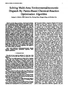
Fig.
1.
Parameters of controlled system, graphical interpretation.
-iE+
4
z 0
TRIM GENERATION AVAILABLE N DESIRED GENERATION ON ALL AUTO UNITS Gd
NIED
ASI
R TRIM
dGENERATION
w
z
No
R E
w
0D 0)
ASSIGNED BLOCK-LOADED GENERATION B (ALSO HY,DRO Gah)
0
TIME
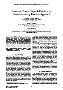
Fig. 2. Parameters of dispatch algorithm, graphical interpretation.
If the ith turbine is available for regulation but is not currently in regulating status, this turbine along with the regulating capacity of the next block ANa is recorded in a "regulation availability list." If the ith turbine is currently in regulating status, it does not appear in the regulation availability list. However, this turbine along with the block-load increment ABi does appear in the blockload availability list. Should the computer decide to utilize this block-load increment, the next valve range is added to the regulation availability list. The regulating cap)acity lost in assigning this block-load increment is reassigned to a unit on the regulation availability list if required. The "trim generation available" N is defined as the sum of the regulating capacities of all uniits in regulating status, i.e., N
=
807
al.: ECONOMIC DISPATCH VIA VALVE-POINT LOADING
2; N (sum
over
all units supplying regulating capacity).
This also includes any hydrogenieration that is to be considered regulating capacity. The computer insures that there is always a mililnmuI of i R MW assigned regulating capacity that could absorb ehanges of R MW in systemn generation. Fig. 1 shows a graphical interpretation of some of the previously defined quantities. This represents the condition where AR = 0 and B = Ba.
as
DISPATCH ALGORITIIM As area requirement and incremental cost force Philadelphia Electric Company's generation up or down, its generation capacity is added or subtracted in such a manner as to maintain the minimum (4R) MW of regulation capacity. Therefore, the satisfaction of regulating requirements forms the basis for all changes in system automatic generation.
Durinig each dispatch cycle, there are four things to be considered in allocating system automatic generation: 1) the prevailing load trend 2) generation assigned and actual generation 3) total regulating capacity requirement 2R 4) cost of available generation. As was mentioned in the Introduction, some amount of foreknowledge of load trend is essential to successful operation of a valve-point loading program. This dispatch algorithm will use a predictive filter to classify the prevailing load trend as being certainly increasing, certainly decreasing, or essentially steady state. The predictive filter will be the subject of a, future paper. A decision to change generation can not be made on just the difference between the desired generation Gt and the actual system generation Ga, because during a previous dispatch cycle a decision to load a particular valve block may have been made, and that block has not been completely loaded. Therefore, it is necessary to consider assigned generation rather than actual generationi for block-loaded units. Ba and Naa have previously been defined, respectively, as the actual gen-eration from valvepoint loaded uniits and actual trim generation. To incorporate this in the logic, two new terms must now be defined. Gd = desired generation on units on automatic control, including hydro units Na = assigned trim generation. Gd is found by subtracting the manual generation Gamn from the system desired generation Gt. B is equal to the assigned valvepoint generation. The quantity N is defined as the sum of all AN for regulating units. The assigned trim generation is foutnd by
Na - Gd
-
(1
-
7) Gah- B
- N.
This assumes that Sy pu of the hydrogeneration is available as regulating capacity. The difference between B and Ba is a very important quantity in monitoring system performance. Specifically, the rate of which Ba approaches B is the combined rate of change of those units changing valve assignmelnts. Generally, it reflects the rate at which the actual generation is approaching the desired generation and, therefore, reflects the company's ability to respond to load changes. Since any difference between B and Ba is carried by the regulating units, it is quite possible that sluggish response rates can cause the entire regulatinig capacity to be used to compensate for this deficiency. With this possibility the quanitity B - Bal should be compared to R and the load dispatcher alerted any time |BBa| is greater than 1/2 R. In order to combine conveniently the above conisiderations with the regulation capacity commitment, two new quantities are defined. The quantity E+ is defined as the regulating capacity above required and is found by E+
=
(N - Na) - R.
The quantity E- is defined as the excess regulating capacity below required and is found by E-
=
Na - R.
These quantities can be interpreted graphically as shown in Fig. 2. It is necessary that certain incremental cost data be maintained in tables or lists along with information on current block sizes and current allowable rates of change. The block-load incremental
808
IEEE TRANSACTIONS ON
cost for the next available block-load increment on the ith turbine is designated Xi and is recorded in a block-load availability list along with the block size AB1. The regulating incremental cost for the next available block of regulating capacity is designated Xi and is recorded in the regulation availablity list along with the block size ANt. It is convenient to define a number of system quantities which are also of interest. The quantities X* and X* represent the highest incremental cost of all currently employed block-load increments and regulating block increments, respectively. The quantities S and S* represent the sum of the two lowest cost block-load increments currently available and the sum of the two highest cost block-load increments currently loaded, respectively. With all these definitions and conditions, it is possible now to construct a logic diagram of the dispatch algorithm. DISPATCH LOGIC In the development of an automatic economic dispatch system, the actual dispatch logic is the heart of the system, but is only a small portion of the total system logic. Since this paper deals only with the dispatch logic, certain functions will be assumed previously completed. 1) The necessary inputs from each station have been read, scaled, and checked. 2) The current status of each machine is checked against previous dispatches to determine if it is responding to load requests Ba -e B and to update allowable rates of change. 3) The Philadelphia Electric Company's running cost for this dispatch cycle and the megawatts Gt corresponding to this cost have been computed. 4) All unit information has been updated in the stored tables, and the block costs have been adjusted for transmission losses based on the system actual generation. 5) The predictive filter has classified the load trend as being certainly increasing, certainly decreasing, or essentially steady state. 6) Decisions relative to hydrogeneration have already been made. 7) The list of available units has been checked to determine if, because of a recently removed constraint, a unit is operating far above or below system incremental cost. Appropriate action has been initiated to bring this unit to the right economic level. 8) The following calculations have been made and adjusted for any decisions made in 6) or 7) above: B = 2 AB
N = 2 AN N= 2.N
G- Gam - (1 E+ = N - Na - R
Na
=
-
y) Gah - B
-
N
E- = Na - R.
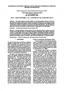
9) The quantities X* and X* have been determined, and the tables of unit costs have been ordered by ascending costs. Fig. 3 is a composite diagram of the dispatch logic for all three load trends. Each load-trend condition will be explained separately, and that portion of Fig. 3 associated with that situation will be shown in subsequent diagrams. The dispatch logic for each load trend can be divided into three subgroups. The first subgroup contains those logic decisions concerned with changes in block-load increments-changes in B.
POWER
DOWNWARD TREND
UPWARD TREND
FSE-T ALL TREND
SET ALL TREND SWITCHES TO
SWITCHES TO
~
l
1 I A
~
STEADY STATE TREND SET ALL TREND SWITCHES TO
$.
3.. ~~~2
ES
N
\YES
1>
NEI I ~~~~~UNIT
UNIT.
YESX
:S YES
ESW
,; E+ AND E-l X NO ASSIGN ABE
XaJA XTREND NO
>
AND S*I ~~~~~~~~~~~S
L
|CALCULATE| |ASSIGN NW T BE
NEW
1969
APPARATUS AND SYSTEMS, JUNE
CALCULATE3,* N NO
TRENDSIYES
YEYS I
NEW S+ S
|
E9S