International Journal of Constructive Research in Civil Engineering (IJCRCE) Volume 2, Issue 3, 2016, PP 8-15 ISSN 2454-8693 (Online) DoI: http://dx.doi.org/10.20431/2454-8693.0203002 www.arcjournals.org
Edge Points Detection in Unorganized Point Clouds Andreas A. Sidiropoulos PhD Candidate Laboratory of Geodesy & Geomatics, Department of Civil Engineering, Aristotle University of Thessaloniki, Thessaloniki, 54124, Greece
[email protected]
Konstantinos N. Lakakis Associate Professor Laboratory of Geodesy & Geomatics, Department of Civil Engineering, Aristotle University of Thessaloniki, Thessaloniki, 54124, Greece
[email protected] Abstract: Laser scanning is one of the main methodologies that is being widely used by surveying engineers for geometric documentation of sights and objects. Laser scanners provide large point clouds that depict the surface of the area or object under investigation. Modern scanners are able to create point clouds of such a density that in many cases the production of the 3D model is not necessary. Basic operations, such as cross sections and distance measurements, can be made directly to the point cloud. On the other hand, that big amount of datasets requires the appropriate tools of elaboration and extraction of the significant information. In this paper, we made an approach to distinguish, among each other, objects that exist in the same scanning scene. The detection of the points that are on objects’ edges provide firstly the knowledge of the space that objects occupy and thus we are able to separate them from their surrounding space and secondly provide the user with the convenience of calculating their geometric parameters. The suggested method makes use of the k nearest neighbors of a point and the closeness of those neighbors to the point of interest.
Keywords: Edge points, laser scanning, point cloud
1. INTRODUCTION The most of the modern measuring technologies are able to provide large number of points of the sight or the object that is being measured. These large numbers of points are being called point clouds. The creation of point clouds may happen by making measurements using active devices, like laser scanners. These instruments create their own radiation and by directing it to the surface under documentation they are able to calculate the coordinates of points. Time of flight (tof), phase based and based on the triangulation theories are the main three categories of laser scanners depending on their working principle. Tof laser scanners emit a pulse towards the object of interest and measure the time that it needs to reach it, to be reflected on it and return to the device. Having acquired the time of flight it is easy to calculate the distance between the object and itself. Simultaneous storage of the horizontal and vertical angle at the moment of emission provides the calculation of the point’s coordinates. Phase based scanners also measure the time between emission and reflection, but they compare the phase of the emitted wave to the one that is being received and calculate the respective time space. The triangulation laser scanners, as their name reveals, use the principles of the triangulation theory to calculate coordinates. Additionally to the emitting device, they contain a CCD camera, at known distance to it, which is able to spot the reflected pulse on the object’s surface. So, making use of the triangulation theory at the triangle “emitting device-spot on the object-CCD camera” they calculate the coordinates of the spot-point. Another category of instruments that are being used to geometric documentation are the digital cameras that store photographs of the area under investigation. These devices are passive, which ©ARC
Page | 8
Andreas A. Sidiropoulos & Konstantinos N. Lakakis
means that they do not create any kind of radiation, but they take advantage of the sunlight that is being reflected on the objects. The production of point clouds is able by implementing special software that makes use of the photogrammetric principles. Independentlyof the source that is being used to create them, point clouds are very important to geometric documentation of sights, heritage monuments and objects. They contain the information to define and measure the world and the things that it includes. The most common information that exist in point clouds that depict the 3D space which surrounds us is the XYZ coordinates of each individual point. The exploitation of these three parameters leads to the knowledge of the dimensions and properties of natural and man-made entities. Also,many point cloud operations exploit the RGB and intensity information that is being provided by most measuring devices. The extraction of geometric information of objects require the isolation of the points that describe the object itself by the rest of the point cloud. To achieve that, we should detect the points that represent the boundaries of the object. At the present approach, the detection of points that exist on objects’ edges is made by the use of the neighborhood of points and the comparison of the relative position among them.
2. RELATED WORK Edge detection has been a very important issue when it comes on computer vision and graphics. The fact that the image has been the basic tool for many applications, led to the development of many algorithms for image edge detection. Especially for line edges, wide use of Hough transform has been made. The Hough transform is a voting procedure that aims to fit a structure to a set of data [1]. The implementation of various detection techniques with the use of Hough transform was made by [2]. The authors compared the results of each detection method to the same original image and concluded that canny edge detector provided better results in noisy image than any other tested operator. Canny algorithm is one of the most important edge detection techniques. It was developed by John Canny in 1986 and was introduced at his paper “A Computational Approach to Edge Detection”. Its operation is based on three criteria. The first is the low error rate criterion which means that no edge that exists in an image should be missed and no edge attribution should be occurred at non-edge areas. The second criterion is that the edge attribution should be as close as possible to the real edge and the third criterion is that there should be only one edge attribution to every single edge. Canny algorithm is considered by many as the optimal edge detector [3]. Two main categories of edge detectors are the Gradient based and the Laplacian based. The first finds edges using the maximum and minimum of the image’s first derivative. The second category spots zero crossings of the second derivative of the image to find edges. In one dimension an edge has the shape of a ramp, so the calculation of the derivative of the image can indicate its location [4]. The implementation of edge extraction techniques in unorganized point clouds was made by [5]. The authors of this study detect sharp edges by analyzing the eigenvalues of the covariance matrix that are being calculated by the k nearest neighbors of each point. A technique of edge detection and its contribution to point cloud registration was introduced by [6]. The method uses RGB-D point clouds and combines the exploitation of the 3D shape and texture information. Also, the efficient edge detection is accomplished by the organized structure of RGB-D images. The results of the detection are being used to perform edge-based registration between pairs of data. A contour detection algorithm in unstructured 3D point clouds was developed by [7]. The authors point out the significance of contour detection -lines along which the orientation changes sharply- to converting point clouds into surface or solid models. They use a two stage method. Firstly, they give to each point of the point cloud a contour score with a binary classifier, using features that were extracted by its neighborhood. At the next step, a further binary classification is performed to select an optimal set of contour candidates. This further classification prefers connected contours and penalizes loose ends. The creation of a curve network that indicates the edges of surface patches is proposed by [8]. They use a first order segmentation to extract candidate feature points which are processed as a graph to recover sharp feature lines. Finally, a minimum spanning tree is created and a reconnection method closes the lines. International Journal of Constructive Research in Civil Engineering (IJCRCE)
Page | 9
Edge Points Detection in Unorganized Point Clouds
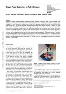
3. EXPERIMENT 3.1. Method If we consider a point cloud as a global scene which consists of separate objects, the idea of detecting the edges in that scene lies on finding the boundaries that constitute each object an individual entity. The fact that we acquire the boundary points of a scene lets us implement various other operations and calculations. The main tool that is being used for the detection of points that are located on objects’ edges is the k nearest neighbors. The algorithm of k nearest neighbors is widely used in supervised classification, pattern recognition and machine learning for categorizing objects in point clouds depending on their properties. In the case of XYZ unorganized point clouds, that the onlyavailable information is the position of points in 3D space, k nearest neighbors is a very efficient method to examine the relation among points. As the word “neighborhood” indicates, the technique examines relations among points locally. The definition of local depends on two main parameters. 1) Density The density of a point cloud is defined by the distance among the points. So, a high dense point cloud indicates that the points are very close to each other. On the other hand, low density means that points are not that close. 2) The parameter k The parameter k indicates the number of points that will be considered as neighbors around a specific point. So, considering a point q as an interesting point, the k closest points to that point are its k nearest neighbors (Fig. 1).
Fig1. k nearest neighbors of point q. In this case k=9.
The fact of how close or how far is a point to another is usually calculated by their Euclidean distance. Especially in our case, that the points are geometric entities Euclidean distance defines the closeness among them. Although, if we consider the large variety of applications and the different relations that may need to be examined, Euclidean distance is not always preferred, even if the problem is geometric. Table I shows other available distance metrics that are at users’ disposal. Table I. Distance Metrics 𝑑 𝑥, 𝑦 = Cosine metric
𝑑 𝑖=1 𝑥𝑖 𝑦𝑖
𝑥∙𝑦 = 𝑥 𝑦
𝑑 2 𝑖=1 𝑥𝑖
𝑑 2 𝑖=1 𝑦𝑖
𝑑
Canberra metric Lagrange metric Lance - Williams metric Manhattan metric
𝑥𝑖 − 𝑦𝑖 𝑖=1 𝑥𝑖 + 𝑦𝑖 𝑑 𝑥, 𝑦 = max 𝑥𝑖 − 𝑦𝑖
𝑑 𝑥, 𝑦 =
𝑑 𝑥, 𝑦
𝑖=1,…,𝑑 𝑑 𝑖=1 𝑥𝑖 = 𝑑 𝑖=1 𝑥𝑖 𝑑
𝑑 𝑥, 𝑦 = 𝑖=1
− 𝑦𝑖 + 𝑦𝑖
𝑥𝑖 − 𝑦𝑖
International Journal of Constructive Research in Civil Engineering (IJCRCE)
Page | 10
Andreas A. Sidiropoulos & Konstantinos N. Lakakis
The k nearest neighbors can be defined for the whole point cloud or for specific points. In our case we calculate the k nearest neighbors for each one point of our data. This means that a point can be included to the neighbors of more than one of the other points. As it is clear, the way that the method is being implemented in our algorithm is not working like the Voronoi diagram. In Voronoi diagram, each point defines a zone that is closer only to it. The number of parameter k influences the results of the algorithm and it is user sensitive depending on the requirements of the application. Once the k nearest neighbors have been found our algorithm calculates, using (1)-(3), the parameters 𝑉𝑋 , 𝑉𝑌 , 𝑉𝑍 for each point of interest and for each one of the coordinates X, Y and Z. 1
𝑘 𝑖
𝑥𝑖 − 𝑥𝑞
(1)
1
𝑘 𝑖
𝑦𝑖 − 𝑦𝑞
(2)
1
𝑘 𝑖
𝑧𝑖 − 𝑧𝑞
(3)
𝑉𝑋 = 𝑘−1 𝑉𝑌 = 𝑘−1 𝑉𝑍 = 𝑘−1
Where k is the number of neighbors, 𝑥𝑖 , 𝑦𝑖 , 𝑧𝑖 are the coordinates of each neighbor and 𝑥𝑞 , 𝑦𝑞 , 𝑧𝑞 are the coordinates of the query point. The parameters 𝑉𝑋 , 𝑉𝑌 , 𝑉𝑍 provide a degree of the deviation of each neighbor from the query point. Then, the range of all the values of the parameters 𝑉𝑋 , 𝑉𝑌 , 𝑉𝑍 is being calculated by (4)-(6). 𝑅𝑋 = max (𝑉𝑋 ) − min (𝑉𝑋 )
(4)
𝑅𝑌 = max (𝑉𝑌 ) − min (𝑉𝑌 )
(5)
𝑅𝑍 = max (𝑉𝑍 ) − min (𝑉𝑍 )
(6)
The last step of the calculations is based on the comparison of each value of the parameters 𝑉𝑋 , 𝑉𝑌 , 𝑉𝑍 to the respective range, as it is being shown by (7)-(9). 𝑎𝑏𝑠 𝑉𝑋 > 𝑎𝑏𝑠(𝑅𝑋 )/C
(7)
𝑎𝑏𝑠 𝑉𝑌 > 𝑎𝑏𝑠(𝑅𝑌 )/C
(8)
𝑎𝑏𝑠 𝑉𝑍 > 𝑎𝑏𝑠(𝑅𝑍 )/C
(9)
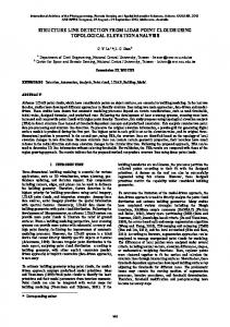
Where C is a parameter that is related to the number k that has been chosen. If at least one of (7)-(9) is real, the respective query point is considered as an edge point. 3.2. Tests of the Algorithm on Scans The tests of the edge detection algorithm were made using parts of scans that were measured at the laboratory facilities of the Aristotle University of Thessaloniki and captured by the phase based Faro Focus 3D S120 laser scanner. Another set of scans that our algorithm was tested on, was those that were captured by the triangulation NextEngine laser scanner. The data of the Faro laser scanner are parts of two solids that have been scanned with the purpose of calculating their real edge length with high accuracy. At this point becomes obvious the importance of the edge detection techniques, since the accurate calculation of the dimensions of the objects needs the isolation of the points that describe their sides and not all of their area: 1) Point cloud of one of the sides of a cube (theoretic edge length 12cm) 2) Point cloud of two neighboring sides of a pyramid (theoretic base edge length 10cm and slope edge length 12cm) The data of the Next Engine laser scanner are a scene of various handheld objects and a cup. 3.3. Results The algorithm was tested using four different scenes, two for each recording device. Three different values (5, 11, 25) where attributed to the parameter k of the nearest neighbors that were used for the tests. The values of the number C were k+10, k and k-15 respectively. Because of space efficiency the figures that will be displayed will be only for the values of k 5 and 25. The first scene tested was the side of the cube (Fig. 2). International Journal of Constructive Research in Civil Engineering (IJCRCE)
Page | 11
Edge Points Detection in Unorganized Point Clouds
Fig2. The side of the cube.
TableII shows the values of the parameters k and C and the respective results and (Fig. 3)-(Fig. 4) show their visualization. Table II. Values of Parameters k, C and Resulting Points for the Side of the Cube k 5 11 25
C 15 11 10
Scene Points 1801
Edge Points 210 240 273
Fig3. The point cloud of the cube’s side. k=5, C=15. The colored red dots are the edge points (210 out of 1801).
Fig4. The point cloud of the cube’s side. k=25, C=10. The colored red dots are the edge points (273 out of 1801).
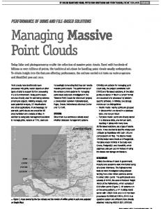
The differences among the three examples are not very important. Even the number of points that have been classified as edge points does not change significantly. On the other hand, the values of the parameters k and C must be very careful assigned in the case of the two sides of the pyramid (Fig. 5) because as the number of neighbors is being reduced the results tend to be very disappointing as it is obvious at Table III and (Fig. 6)-(Fig. 7).
Fig5. The two sides of the pyramid. International Journal of Constructive Research in Civil Engineering (IJCRCE)
Page | 12
Andreas A. Sidiropoulos & Konstantinos N. Lakakis Table III. Values of Parameters k, C and Resulting Points for the Sides of the Pyramid k 5 11 25
C 15 11 10
Scene Points 862
Edge Points 684 323 181
Fig6. The point cloud of the two sides of the pyramid. k=25, C=10. The colored red dots are the edge points (181 out of 862).
Fig7. The point cloud of the two sides of the pyramid. k=5, C=15. The colored red dots are the edge points (684 out of 862).
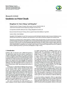
In the case of pyramid it is obvious that the user should give serious consideration on the value of the parameter k, unless they will not have the expected results. The third point cloud that was used to test our algorithm was a scene that includes various handheld objects (Fig. 8).
Fig8. A scene of handheld objects.
The results of the third scene examination are shown at Table IV. Without important differences the implementation of our algorithm gave similar results. The best edge detection result occurred for the value of k=11 (Fig. 9), in the sense that no much noise was introduced and the edges remain as thin as possible. International Journal of Constructive Research in Civil Engineering (IJCRCE)
Page | 13
Edge Points Detection in Unorganized Point Clouds
Fig9. The point cloud of the scene of handheld objects. k=11, C=11. The colored red dots are the edge points (2923 out of 31149). Table IV. Values of Parameters k, C and Resulting Points for the Scene of Handheld Objects k 5 11 25
C 15 11 10
Scene Points 31149
Edge Points 3800 2923 3354
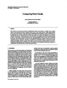
The last example of our algorithm implementation was a point cloud of a cup. The results are shown at Table V. Once again the best performance of our algorithm was made for the value of k=11 (Fig. 10). Using this value the algorithm managed to capture more edges than the other two values simultaneously introducing the less noise. Table V. Values of Parameters k, C and Resulting Points for the Cup k 5 11 25
C 15 11 10
Scene Points 5365
Edge Points 1362 1021 901
Fig10. A point cloud of a cup.k=11, C=11. The colored red dots are the edge points (1021 out of 5365).
4. CONCLUSION The edge detection has concerned many scientists of computer vision and graphics, feature detection and shape extraction using datasets of images or point clouds. The knowledge of the edges’ position makes more efficient the elaboration of the data and the extraction of the information that they contain. The algorithm that is being introduced in this paper is able to detect edges under the supervision of the user who needs to observe the results and make adjustments if necessary. Future work includes more tests on point clouds that represent larger areas and exploitation of the algorithms results to acquire as more accurate as possible the shape of the objects that are being scanned. International Journal of Constructive Research in Civil Engineering (IJCRCE)
Page | 14
Andreas A. Sidiropoulos & Konstantinos N. Lakakis
REFERENCES [1] D. A. Forsyth, and J. Ponce,“Computer vision: a modern approach”,Prentice Hall Professional Technical Reference, 2002. [2] S.Singh, and A. Datar,“EDGE Detection Techniques Using Hough Transform”,Int. Journal of Emerging Technology and Advanced Engineering, 3(6), pp. 333-337,2013. [3] B.Green. (2002) "Canny edge detection tutorial" Available: http://www. pages.drexel.edu/~ weg22/can_tut.html [4] R. Maini, and H.Aggarwal,“Study and comparison of various image edge detection techniques”Int. journal of image processing (IJIP), 3(1), pp. 1-11, 2009. [5] D. Bazazian, J. R. CasasandJ. Ruiz-Hidalgo, “Fast and Robust Edge Extraction in Unorganized Point Clouds” In Digital Image Computing: Techniques and Applications (DICTA), Int. ConferenceIEEE, 2015, pp. 1-8. [6] C. Choi, A. J. Trevor and H. I. Christensen,“RGB-D edge detection and edge-based registration” In IEEE/RSJ Int. Conference on Intelligent Robots and Systems IEEE, 2013,pp. 1568-1575. [7] T. Hackel, J. D. Wegnerand K. Schindler.“Contour detection in unstructured 3D point clouds”, CVPR, 2016 [8] K. Demarsin, D.Vanderstraeten, T.Volodine and D.Roose. “Detection of closed sharp edges in point clouds using normal estimation and graph theory”, Computer-Aided Design, 39(4), 276283, 2007.
International Journal of Constructive Research in Civil Engineering (IJCRCE)
Page | 15