ECCM16 - 16TH EUROPEAN CONFERENCE ON COMPOSITE MATERIALS, Seville, Spain, 22-26 June 2014
EFFECT OF 3D REINFORCEMENT ON DYNAMIC BEHAVIOR OF COMPOSITE MATERIALS USING SHPB TECHNIQUES: EXPERIMENTAL INVESTIGATION
M. Tarfaouia*, C. Bouerya, A. El Malkia a
ENSTA Bretagne,MSN/LBMS/DFMS, 2 rue François Verny 29806 Brest Cedex 9, France *
[email protected]
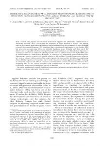
Keywords: 3D woven composite, Delamination, Dynamic compression, Damage kinetics Abstract A series of Split Hopkinson Pressure Bar tests on 2D and 3D woven composites were presented in order to obtain a reliable comparison between the two types of composites, and the effect of the z-yarns along the 3rd direction. These tests were done along different configurations: in-plane and out-of-plan compression test. For the 3D woven composite, two different configurations in the plane were studied: compression responses along to the stitched direction (SD), and orthogonal to the stitched direction (OSD). It was found that 3D woven composite exhibit an increase in strength for both: in-plane and out-of-plane tests.
1. Introduction
Composite materials are increasingly being used as a substitute for metallic materials in many technological application like aeronautics, aerospace, marine, armor, automotive and civil engineering applications [1,2,3]. Many of these applications, the structure are subjected to high impact loading. The mechanical behavior of composites being dependent on loading rate [4,5,6], knowledge of constitutive models is of interest of scientists and designer. Delamination of 2D composites is known to be one of the most critical problems for designing composite structure, especially when impact loading is present. For this 3D composites were introduced in order to enhance the delamination resistance, by introducing zyarns (or binder yarns) that weave multiple laminas [7]. During the weaving process, the resulting created spaces (due to wrapping of lamina tows) are filled with matrix material which in turn causes low fiber volume fraction thus degradation of in-plane material properties [8]. Several tests were conducted on 3D reinforced composites. Tensile tests at low loads revealed crack initiation, associated with the resin rich areas near the z-yarns [9, 10]. Whereas compressive tests showed a significant increase in the mode I, and moderate increase in mode II fracture toughness [11,12,13]. Transverse impact tests shows that the damage is independent on the loading rate, and it was noted that through-the-thickness reinforcement prevented delamination [14]. High velocity ballistic impact tests showed that z-yarns weaving did not prevent delamination, at rates higher than the ballistic limit, but it has reduced the damage during the shock [15,2]. In this manuscript a comparative study of impact process 1
ECCM16 - 16TH EUROPEAN CONFERENCE ON COMPOSITE MATERIALS, Seville, Spain, 22-26 June 2014
under high impact loading responses and damage induced for 2D and 3D glass fiber vinylester woven composite is presented. 2. Test principle
2.1. Composite specimen The 2-D and 3-D woven composite (2DWC & 3DWC) shown in figure (1a) & (1b), respectively, were manufactured with the same vinylester matrix (DION 9102) and E-glass fibers, and have the same characteristics. The vinylester resin can be used as an alternative to polyester and epoxy materials in matrix or composite materials, where its characteristics, strengths, and bulk cost intermediate between polyester and epoxy. Vinylester has lower resin viscosity (approx 200 cps) than polyester (approx 500 cps) and epoxy (approx 900 cps), and has good characteristics in a corrosive medium and under high temperature, therefore it is well adapted for naval application [14, 15]. The E-glass woven fiber of 500 g/m2 are known of having high strength/mass ratio and a low cost compared to other reinforcements, therefore they are commonly used for naval applications. The reinforcement consists of a plain weave fabric with 50% warp yarns and 50% weft yarns. The composite used in this study has a thickness of 12 mm. Several tests were done along the in-plane compression test. For in-plane test, the 3D composite is performed along two different planes: compression along the stitched direction (3DWC-SD) and orthogonal to the stitched direction (3DWC-OSD). Note that only one binder yarn is stitched in the middle of the specimen.
2.2. Split Hopkinson pressure bar testing The split Hopkinson pressure bar (SHPB) test is a technique of characterization that is based on the material response to 1-D wave propagation for high strain rate from 100 to 5000 s−1. In these dynamic compression tests, a cubic sample of size 12 mm × 12 mm cut from the composite tile is placed between the two bars, of same diameter 20 mm. The striker, incident and transmitted bar has a length of 0.8 m, 3 m and 2 m, respectively. These bars are correctly aligned and are able to slide freely on the base. The composite is not attached to the bar in order to prevent perturbations of measurements due to additional interfaces [16]. Figure 1 shows the schematic of classical SHPB setup. The striker is lunched with an initial impact pressure provided from the gas gun. A stress wave is generated from the impact of the striker on the incident bar, propagates through the incident bar until it reaches the interface (incident bar/specimen), where it divides into two parts: a reflected part that goes back through the incident bar and a transmitted part goes through the specimen. The stress waves are recorded by the strain gauges mounted on the incident and transmitted bar. More details of SHPB can be found in [17, 18]. The experimental setup consists of: Stress generating system which is comprised of a split Hopkinson and the striker Specimen Stress measuring system made up of sensors (strain gages) Data acquisition and analysis system High speed camera (120000 fps) with multiple trigger interfaces
2
ECCM16 - 16TH EUROPEAN CONFERENCE ON COMPOSITE MATERIALS, Seville, Spain, 22-26 June 2014
Figure 1. Split Hopkinson bar apparatus.
The specimens were subjected to different impact pressure, and the resulting signals were recorded by a digital oscilloscope. Loads on each face of the specimen are given by: (1) (2) where A is the cross section area of the bar, F1 and F2 denote the incident and transmitted load, respectively. The impact energy is the total energy available at the beginning of loading, which is the kinetic energy of the striker bar. This energy is completely transferred into the input bar and can be determined from the measured strain profile:
(3)
where ti is the time of arrival of the compressive wave at the strain gage location, and is the duration of the initial rectangular waveform. As figure (2) shows, for each test a minimum of three tests were achieved for each impact pressure (impact energy) in order to verify the test reproducibility. Figure (3) shows the correlation between the impact pressures (P) provided from the gas gun and the impact energy of the striker on the incident bar.
3
ECCM16 - 16TH EUROPEAN CONFERENCE ON COMPOSITE MATERIALS, Seville, Spain, 22-26 June 2014
Figure 2. Test reproducibility for the composite specimen.
Figure 3. Impact energy vs. impact pressure.
3. RESULTS AND DISCUSSIONS
3.1. Dynamic response Figure (4) shows load-displacement curves when the material is subjected to three different impact energies. For each case, the load increases significantly at initial loading stages until it reaches a maximum value, then decreases gradually. The maximum load increases with increasing impact energy. These figures show that the specimen fails drastically for the 2D and 3DWC-OSD for high impact energy , whereas 3DWC-SD composite did not fail for same rates.
4
ECCM16 - 16TH EUROPEAN CONFERENCE ON COMPOSITE MATERIALS, Seville, Spain, 22-26 June 2014
(a)
(b)
(c) Figure 4. Load-displacement history for in-plane test: (a) 2D woven composite (b) 3DWC-SD (c) 3DWC-OSD.
The load-displacement response shows a rate dependent behavior of the material at these rates. Figure (5) shows an increase of strength with increasing impact energy for different specimens. For low impact energy the strength i s nearly identical for different composite, whereas for higher impact energy the 3DWC-SD shows higher resistance to damage when compared to the two others. 5
ECCM16 - 16TH EUROPEAN CONFERENCE ON COMPOSITE MATERIALS, Seville, Spain, 22-26 June 2014
Figure 5. Strength vs. impact energy for in-plane test.
3.2. Failure mode Figures ( 6 ) , ( 7 ) a n d (8) show the failure mode of different composite specimens at different impact energies. As the impact energy increases, the energy absorption increases, resulting a larger damage area. For in-plane test, the 3DWC-SD failed for higher impact energy, in comparison with the two other cases (2D and 3DWC-OSD). The 2D woven composite failed catastrophically (figure (8)). Damage initiation consisted of a shear bad forming a ’V’ shape and appearance of delamination on its tip. As damage mechanism progresses, it manifests in terms of matrix/fiber failure, fiber pullout, and severe delamination of packs of plies.
Figure 6. In-plane failure mode for the 2D woven composite at an impact energy of 104 J.
For about the same impact energy, the 3DWC-OSD failed less severely, and damage consisted mostly of shear banding forming a ’V’ shape along the diagonal. As damage propagates, delamination is manifested, but often prevented from propagating due to the binder yarn (z-yarn) reinforcement.
6
ECCM16 - 16TH EUROPEAN CONFERENCE ON COMPOSITE MATERIALS, Seville, Spain, 22-26 June 2014
The 3DWC-SD showed higher resistance to damage (>150 J) in comparison with the 2D and 3D-OSD (100 J), and the failure mode contains a shear band forming along the diagonal, and follows many of the different warp and weft tows in the specimen (see figure 10). It has also been noticed that often individual tows (weft and warp tows) remain intact except where they have sheared across.
Figure 7. In-plane failure mode for 3DWC-OSD, at an impact energy of 109 J.
Figure 8. In-plane failure mode for 3DWC-SD, at an impact energy of 165 J.
4. Conclusion
A SHPB was used to conduct high rate compression tests for 2D and 3D woven composite. These tests showed the capacity of the 3DWC to prevent delamination because of 3-direction 7
ECCM16 - 16TH EUROPEAN CONFERENCE ON COMPOSITE MATERIALS, Seville, Spain, 22-26 June 2014
yarn in the specimen. Mechanical behavior and damage mode were presented for both composite along in-plane direction. Two different configurations were studied for the 3D composite when loaded along the plane: a compression test along the stitched direction (3DWC-SD) and orthogonal to the direction where the z-yarn is stitched (3DWC-OSD). In these tests, material strength increases with increasing impact energy. Morphologies of the damaged composite specimens show the different failure modes for 2D and 3D composites along different configurations. Failure mode for the 2D composite consists of delamination, whereas for 3D composites it consists of shear banding for in-plane test. Acknowledgements The authors of this paper gratefully acknowledge the financial support of the DGA.
References [1] M. Tarfaoui, S. Choukri and A. Neme. “Effect of fiber orientation on mechanical properties of the laminated polymer composites subjected to out-of-plane high strain rate compressive loadings”. Composite Science and Technology, Volume 68, Issue 2, 477485, 2008. [2] P. Kumar and B.D. Agrawal. “Dynamic compressive behavior of unidirectional GFRP for various fiber orientations”. Mater Letter, 4(2):111-6, 1986. [3] A. El-Habak. “Mechanical behavior of woven glass fiber-reinforced composites under impact compressional load”. Composites 1991; 22(2):129-34. [4] W. Goldsmith, C.K.H. Dharan and H. Chang. “Quasi-static and ballistic perforation of carbon fiber laminates”. International Journal of Solids and Structures, 32(1):89-103, 1995. [5] J. Tsai and C.T. Sun. “Dynamic compressive strengths of polymeric composites”. International Journal of Solids and Structures, 41(11-12):3211-3224, 2004. [6] M. Tarfaoui. “Experimental Investigation of Dynamic Compression and Damage Kinetics of Glass/Epoxy Laminated Composites under High Strain Rate Compression”. Book: Advances in Composite Materials. Chapter 16 pp 359-382, 2011. [7] AP. Mouritz. “Review of z-pinned composite laminates”. Composites Part A. Applied Science and Manufacturing, 38:2383-97, 2007. [8] AP. Mouritz. “Ballistic impact and explosive blast resistance of stitched composites”. Composites Part B: Engineering, 32:431-9, 2001. [9] T. Rys, BV. Sankar and PG. Ifju. “Investigation of fracture toughness of laminated stitched composites subjected to mixed mode loading”. Journal of Reinforced Plastics and Composites, 2009. [10] Y. Luo, L. Lv, B. Sun, Y Qiu and B. Gu. “Transverse impact behavior and energy absorption of three-dimensional orthogonal hybrid woven composites”. Composite Structures 81:202-9, 2007. [11] L. Hamitouche. PhD Thesis: “Endommagement et rupture des assemblages en T de structures composites pour des applications navales ». Université de Bretagne Occidentale, 2008. [12] M. Tarfaoui, A. Neme and S. Choukri. “Damage kinetics of glass/epoxy composite materials under dynamic compression”. Journal of Composite Materials 43: 1137-1154, 2009. [13] H. Kolsky. “An Investigation of the Mechanical Properties of Materials at Very High Rates of Loading”. Proceedings of the Physical Society, 62B:676-700. [14] E. Davies and S. Hunter. “The dynamic compression testing of solids by the method of the split Hopkinson pressure bar”. Journal of the Mechanics and Physics of Solids, 11:155-79, 1963. [15] P. Follansbee and C. Frantz. “Wave propagation in the split Hopkinson pressure bar”. Journal of Engineering Materials and Technology, 105:61-6, 1983. 8