Effect of a Weak Magnetic Field on Quantum Cryptography Links M. Brodsky (1), M. Boroditsky (1), M.D.Feuer (1), A. Sirenko (2) 1 : AT&T Labs Research, 200 S. Laurel Avenue, Middletown, NJ 07041 2 : Department of Physics, NJIT, Newark, NJ 07102
[email protected] Abstract We study the performance of a commercial bidirectional Quantum Key Distribution system in the presence of a weak magnetic field (about 50 µT) applied along the fiber axis. We observe a quadratic increase in quantum bit error rate with the angle of Faraday rotation. . perpendicular to the spool axis. We further study Introduction Faraday rotation in reflection mode with a Faraday Quantum Key Distribution (QKD) exploits the mirror at the end of the fibers. We find that this quantum-mechanical properties of light to generate rotation is almost linear in magnetic fields up to identical pairs of random secret keys for two parties 250µT, reverses its sign with reversal of the field, connected by an optical fiber. The entire QKD field depends on optical frequency and input polarization surged recently and has already reached its first into the fiber in a fashion similar to PMD. That is, commercial offerings [1]. While integration of these there exists an eigenstate of input state of polarization QKD systems into real networks remains challenging, (SOP), which is not perturbed by the field, and the their range of applicability is of interest to service effect is the strongest for input SOPs, which are 90° providers. away from the eigenstate on the Poincare Sphere. As Both commercially available systems utilize the Faraday effect can not be undone by Alice’s bidirectional technology [2], in which the key is Faraday mirror, it therefore affects performance of the encoded in a photon phase, and polarization effects tested QKD system by increasing quantum bit error in the fiber are selfcompensated with a Faraday rate (QBER) with applied field. By performing QBER mirror at one end. The detailed explanation of such measurements at various input SOPs and in a range scheme can be found elsewhere [3]. Briefly, two of magnetic fields on two fiber spools we determine relatively strong pulses are delayed with respect to an empirical quadratic dependence of QBER on each other by an unbalanced Mach-Zehnder Faraday angle, which is the same for two fibers interferometer at Bob’s end, and are emitted in measured. We speculate that our measurements can orthogonal polarizations. They then travel to Alice not be solely explained by the small tilt of SOPs of the (where they are attenuated to a proper photon count), returning pulses and might arise from changes in the are reflected by a Faraday mirror to return to Bob with relative phase between the two pulses might need to their polarization switched. This ensures that the be taken into account. leading (trailing) returning pulse now enters the long Experimental Setup (short) arm of Bob’s interferometer and as a result Our setup is shown in Fig.1. Two parts of a two of them recombine. Depending on the phase commercial QKD system (Bob and Alice) were delays imposed at Bob’s and Alice’s ends the connected by a spool of fiber. To generate the recombined photon is directed to one of the two magnetic field we wrapped toroidal coils onto the detectors thus producing either “1” or “0”. Because of spool itself and connected them to a current source. A inherent bidirectionality of such scheme, the polarization controller PC2 between Bob and the impairments considered up today are Raman and spool permits variation of input SOP. QBER were Rayleigh backscattering [4] or fast (few hundred recorded by system’s interface. For polarization microseconds) changes in the fiber, which are measurements in magnetic field Bob was comparable to the photon’s round trip time. disconnected and cw light from a tunable laser source There is, however, yet another subtle but potentially passed through a polarization controller PC1, and harmful phenomenon which has been largely then was fed through a 3dB coupler into PC2. A overlooked up to now – Faraday effect in the simple Faraday mirror (FM) was attached to the other transmission fiber itself. When light propagates in end of fiber to replace Alice in such a case. A fibers installed in North-South directions the weak polarimeter picked the reflected signal from another magnetic field of the Earth (which is about 50µT) arm of the coupler. As the fibers were slowly drifting induces small circular birefringence in the fiber. It is during the measurements, we constantly switched believed that much stronger linear birefringence in between two setups, to correlate QBER and the optical fibers quenches the Faraday effect [5]. Faraday rotation angle. Contrary to such belief, in this paper we demonstrate that there exists a small but measurable ALICE BOB test fiber Faraday rotation of few tenth of a radian on three spools of various fiber type ranging between 22 to 26 PC2 km in length, which are placed in toroidal magnet, PC1 laser such that field lines are aligned with the fiber. Note FM 3dB that there is no effect when the same spools are polarimeter placed in uniform field of the same magnitude Fig. 1 QKD path(solid); Polarization path(dashed)
16
1 ) d ar ( θ
0.8 x a m
e gl n a n oi t at o r x a m
0.6
0.4
DSF data DSF linear fit AW data AW linear fit AW another time TW data TW quadratic fit TW another time
14 12 ) % ( R E B Q
10 8 6 4
0.2
0 0
2
0.5
1 1.5 2 magnetic field (in 50 µT)
2.5
3
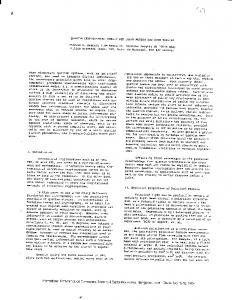
Fig. 2 Faraday rotation vs B for 3 fibers; 1550nm Results Fig. 2 shows the maximum angle of Faraday rotation θmax (corresponding the worst launched condition set by PC2) taken at λ=1550nm for three different spools as a function of magnetic field, which is measured in units the Earth magnetic field (B0=50µT). Filled circles, filled squares and stars correspond to the data for 22.8km DSF (●), 26.4km AllWave (AW) (■), and 25.2km TrueWaveReach (TW) (*) spools. As polarization properties of the AllWave and TrueWave fibers changed in time two more points for these two fibers taken at different time at B= B0 illustrate a range of this variation. Relatively strong effect in DSF and AW seems linear, while smaller effect in TW is quadratic. The maximum rotation angle θmax also varies with wavelength. The values measured on the three fibers between 1530nm and 1570nm at the field of B=B0 range between 0.4 rad (for AW at 1540nm) and 0.1 rad (for TW at 1570nm). To measure QBER we first set the field to a relatively high value (B=2B0) and then vary PC2 to get a high QBER count. Once the proper SOP in found, QBER is taken for the entire field range. System’s interface updates QBER averaged over 10 seconds, and typically we take 6 readings for each point. This gives us a reasonable accuracy of 0.06% but limits the amount of data given temporal drift in fibers. Seven QBER curves are shown in Fig.3 for various SOPs in two different fibers (DSF and AW). Instability of TW fiber together with small values of Faraday rotation at 1550 nm during the time of the measurements prevented us from taking QBER curves on that fiber. The maximal effect for the field 16 14 12 ) % ( R E B Q
DSF data AW data quadratic fit simple SOP tilt
10 8
DSF SOP1 DSF SOP2 DSF SOP3 DSF SOP4 AW SOP1 AW SOP2 AW SOP3
6 4 2 0 0
0.5
1 1.5 2 magnetic field (in 50 µT)
2.5
3
Fig.3 QBER for various input SOP for two fibers
0 0
0.2
0.4 0.6 rotation angle θ (rad)
0.8
1
Figure 4. QBER vs θmax for 2 fibers: quadratic fit (solid), QBER due to SOP misalignment alone (dashed) value B=B0 is measured to be 3.65%, while typical QBER for zero field is 1.55% (maximal 1.88%). Thus we conclude that the effect of the Earth’s magnetic field is not negligible. Naturally, the effect is bigger in larger fields (or presumably in longer spans). Since net Faraday rotation is different in different fibers at any given time, we find it instructive to plot the QBER data as a function of maximal rotation angle θmax (Fig.4). From each set of QBER curves, taken on DSF and AW fibers, we pick two the largest, each one corresponding to the worst launched SOP condition achieved in that fiber. Now we plot them together (● for DSF, for AW) in Fig. 4 as a function of maximal rotation angle θmax measured during the QBER test (note that due to drifts, θmax for AW fiber is about 1.5 times larger than that shown in Fig.2). The two superimposed data sets lay right on top of each other, and, in fact, could be fitted by the same quadratic dependence of the angle: 2 QBER≈ 10.5 ×θmax + 5.2 ×θmax +1
shown as solid
line in Fig. 4. It is interesting to note that a simple polarization misalignment of pulses returning to Bob will only reduce the photon count by
cos2 (θmax/ 2) ,
increasing QBER only slightly (dashed line in Fig. 4). Thus we believe a magnetic field induces some relative phase change between the two pulses. Conclusions Utilizing a commercially available QKD system we performed QBER measurement through various spools of fiber subjected to a weak magnetic field. We found that Faraday rotation by such small fields of 50µT (comparable to that of the Earth) could slightly degrade the performance of QKD system. We obtained an empirical dependence of QBER degradation on the maximal angle of Faraday rotation. Our results suggest that the Earth’s magnetism could influence QKD links over some installed routes. References 1. www.idQuantique.com, www.MagiQtech.com 2. H.Zbinden et al, Electron.Lett. vol. 33,pp.586, 1997 3. N.Gisin et al, Rev.Mod.Phys., vol.74,pp.145, 2002 4. D.Subacius et al, Appl.Phys.Lett., vol.86, 2005 5. R.H.Stolen et al,Appl.Opt., vol.19, pp.842, 1980