Effect of additives on sintering response of titanium by powder injection moulding A. Arockiasamy*1, R. M. German2, D. F. Heaney3, P. T. Wang1, M. F. Horstemeyer1, R. L. King1 and B. Adcock1 Powder injection moulding is a maturing technology that has proven most useful for the production of complex metallic and ceramic components of modest sizes. Considering the inevitable demand for cost effectiveness in automotive applications, components manufactured from low cost sponge titanium (Ti) powder currently reflect the most advantageous economics among the available Ti powders. This paper describes the net shape fabrication of Ti components and considers the role of iron and zirconium powder additions. Sintering cycle optimisation relied on differential scanning calorimetry to identify a cycle in the 1275–1300uC range for 1–2 h. The sintered material was characterised using tensile and hardness testing and microscopic examinations. The influence of test conditions on densification, microstructure and mechanical properties was analysed. Keywords: Titanium alloy, Powder injection moulding, Sintering, Mechanical properties
Introduction Titanium (Ti) is a highly useful material in the production of components for various applications ranging from biomedical implants to automotive fuel injectors. At the same time, the high strength to weight ratio and high resistance to corrosion make Ti and its alloys ideal materials for many of these same applications.1–3 However, a difficulty occurs in fabricating components at a low cost from an expensive material. Considering powder metallurgical production routes, simple die compaction offers limited shape complexity, therefore compaction is not useful in many small component designs. For other fabrication routes, cost is a primary concern; casting followed by machining is prone to defects and suffers from a low productivity.4,5 On the other hand, the powder injection moulding (PIM) process offers a viable solution to these problems, especially the problem of cost of production.6–9 Powder injection moulding involves the injection moulding of a mixture of metal powder and polymer binder into a mould to produce a ‘green’ part, which is then debound and sintered into finished product. Through much research since the late 1980s, it has been determined that the level of impurity elements, powder expenses and mouldability of the powder all have an effect on the success of Ti PIM. Impurities such
1
Center for Advanced Vehicular System, Mississippi State University, 200 Research Boulevard, Starkville, MS 39759, USA 2 College of Engineering, San Diego State University, 5500 Campanile Drive, San Diego, CA 92182-1326, USA 3 Center for Innovative Sintered Products, Pennsylvania State University, University Park, PA 16802-6809, USA *Correspondence author, email
[email protected]
ß 2010 Institute of Materials, Minerals and Mining Published by Maney on behalf of the Institute Received 1 March 2010 DOI 10.1179/003258910X12740974839468
Table 1 Characteristics of powders used Powders
Particle size, mm
Pycnometer density, g cm23
Ti Zr Fe
38 8 16
4.51 6.51 7.87
Powder Metallurgy
Powder Metallurgy pom1641.3d 3/6/10 14:29:47 The Charlesworth Group, Wakefield +44(0)1924 369598 -
as oxygen can dramatically decrease the strength and density of Ti PIM products.10–12 Powder costs vary based on the grade of powder used for PIM, with high purity powders costing significantly more. Furthermore, more easily moulded powders whose particles are smaller and more spherical become more expensive which consequently increases the cost of production. Thus, in an economic analysis the processing difficulties from lower cost powders must be balanced against the ease of processing possible using a spherical Ti powder. There are several cost factors evident in Ti PIM. These include powder handling (Ti is pyrophoric), moulding issues from stiff mixtures and care during debinding and sintering to avoid interstitial contaminants, all factors beyond powder cost that influence production economics. The cost of injection equipment and associated power consumption is fairly modest, but equipment for debinding and sintering as well as the energy, atmosphere and long cycles for these processes vary greatly between PIM technologies. Thus, it is important to minimise the necessary thermal cycle duration while maximising quality of the Ti product. One way of achieving this goal considered in this study is to adjust alloying to enable Ti PIM shapes at low cost, with rapid cycles, and mechanical strength comparable to automotive applications. In this case iron (Fe) and zirconium (Zr) are used as alloying elements,13–15 as Fe
Rev 7.51n/W (Jan 20 2003)
2010
VOL
000
NO
000
1
Arockiasamy et al.
Effect of additives on sintering response of Ti by PIM
ONLINE COLOUR ONLY
2 Injection moulded Ti–5Fe–2?5Zr parts
were mixed into a common wax based binder feedstock and injected and debound under the same conditions, which were determined using thermogravimetric analysis (TGA). Differential scanning calorimetry (DSC) was employed to guide selection of the optimal sintering range. Sintering was conducted at two different peak temperatures for two different hold times for each alloy to determine optimal sintering conditions. The properties and microstructure were evaluated using standard tensile, hardness and scanning electron microscopy (SEM) tools.
Experimental Characteristics of metal powder and binder The Ti powder used in this work was HDH Ti sponge powder provided by Phelly Materials (Bergenfield, NJ, USA). The Zr powder was obtained from Alfa Aesar (Ward Hill, MA, USA) and the Fe powder was obtained from Atlantic Equipment Engineers (Bergenfield, NJ, USA). All powders were 2325 mesh and laser scattering particle size analysis was used to measure the size distribution; the mass based D10, D50 and D90 particle sizes give the 10, 50 and 90% points on the cumulative particle size distribution in Table 1. The morphology of each powder was examined by SEM. To protect the powders from oxidation, all of the materials were stored in an argon atmosphere except when mixing and moulding. A standard binder system is employed, consisting of a paraffin wax (PW) and stearic acid (SA). High molecular weight polymer components used were polypropylene (PP) and polyethylene. A list of these binder components and their characteristics is given in Table 2.
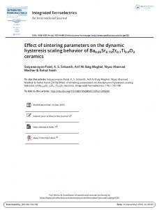
a HDH Ti powder; b Zr powder; c Fe powder 1 Images (SEM) of three metal powders used in this study
has a tendency to stabilise the beta phase and form intermetallics while Zr has a tendency to promote chemical homogenisation. By optimising the sintering conditions and alloying it is possible to obtain nearly full density Ti structures via PIM.3 This article provides a comparison of different PIM Ti alloys made using hydride–dehydride (HDH) Ti powder mixed with varying proportions of Fe and Zr to manipulate phase formation. The metal powder mixtures
Feedstock preparation Solids loading for this study was chosen to be 50 vol.-% to allow for easy flow of the feedstock during injection
Table 2 Properties of polymer binder components Material
Company
Fusabond MB-353D PP IGI 1231A PW
DuPont The International Group, Inc. PolyVisions, Inc. Fischer Chemicals
ProFlow 3000 PP SA
2
Powder Metallurgy
2010
VOL
000
NO
Density, g cm23
Flash point, uC
Boiling point, uC
Melting point, uC
Binder, wt-%
0.88–0.98 0.93
350 .190
… .300
130–160 53.3
9 65
0.9 0.84
315 196
… 361
.140 69
25 1
000
Powder Metallurgy pom1641.3d 3/6/10 14:29:52 The Charlesworth Group, Wakefield +44(0)1924 369598 -
Rev 7.51n/W (Jan 20 2003)
;
Injection moulding was performed using a 20 t Arburg Allrounder 170 U injection moulding machine (Arburg Ltd, Lossburg, Germany). The injection pressure was 750 bar at a fill rate of 10 cm3 s21. The injection temperature was set to 160uC and the mould temperature
6 Sintering cycle for producing final part
Powder Metallurgy
Powder Metallurgy pom1641.3d 3/6/10 14:30:01 The Charlesworth Group, Wakefield +44(0)1924 369598 -
Rev 7.51n/W (Jan 20 2003)
2010
VOL
000
NO
000
3
Arockiasamy et al.
Effect of additives on sintering response of Ti by PIM
ONLINE COLOUR ONLY
7 Green and sintered 90Ti–5Fe–5Zr parts arranged alternatively
Thermal debinding and presintering
The debinding temperature of 550uC was selected and reached at a heating rate of 1 K min21 in an argon atmosphere. This temperature was held for 1 h to allow for polymer evaporation. Then the samples were further heated using a heating rate of 5 K min21 up to 900uC for a hold time of 1 h to improve the green strength of the injected parts. Sintering
?
After removing the binder and presintering, the components were sintered. Two sintering temperatures (1275 and 1300uC) and two hold times (1 and 2 h) were selected for this study. The Materials Research Furnace vacuum system used was an all metal hot zone 0?1 m3 volume equipped with four sided heating (Materials Research Furnaces Inc., Suncook, NH, USA). At the peak temperature the furnace reached a vacuum of 6 kPa.
At least ten measurements were made to ensure accuracy. Tensile test
All tensile tests were performed using Instron 5569 (Instron Corporation, Norwood, MA, USA) mechanical tested at a constant crosshead speed of 1 mm min21 (25 mm gauge length). Metallographic mounts of the sintered alloy were prepared using standard metallographic techniques. Microstructural characterisation was carried out using a JEOL SEM (JEOL Ltd, Tokyo, Japan). To observe the microstructure of the fractured sintered Ti alloys, Kroll’s reagent (3 mL HF, 6 mL HNO3 in 100 mL H2O) was used to etch the samples for microscopy investigations. Energy dispersive X-ray spectroscopy (EDS) attached to SEM analysed the phases present within the microstructure of the sample.
Results and discussion
Density
The SEM images of the powders used are shown in Fig. 1. As seen in these images, both the Ti and Zr powders exhibit irregular shapes. Though this will reduce the packing density of the two metals, the irregular shape should confer higher green strength on the powder assemblies. The characteristics of powders and binders used in this study are tabulated in Tables 1
Hardness
The hardness tests were performed using a LECO-LR at HRB scale (LECO Corporation, St. Joseph, MI, USA). Table 3 Mechanical properties of PIM Ti alloys Green sample
Alloy
Hold time, h
Theoretical density, g cm23
Density, g cm23
Relative density, %
Density, g cm23
Relative density, %
Hardness, HRB
Tensile strain, %
UTS, MPa
Ti
1275
1 2 1 2 1 2 1 2 1 2 1 2
4.51
2.85
63.2
4.64
2.97
64.0
4.68
3.16
67.5
3.62 3.92 3.88 3.91 4.01 4.02 4.00 4.18 4.14 4.27 4.15 3.91
80.3 86.8 86.0 86.8 86.5 86.6 86.2 90.0 88.6 91.2 88.7 83.5
58.9 67.2 64.2 69.7 72.9 76.9 71.9 81.5 74.5 75.7 74.2 72.1
1.26 1.87 0.99 1.41 0.84 0.89 0.32 2.08 2.26 0.94 1.14 0.00
190 539 540 517 459 508 237 512 410 530 548 198
Ti–5Fe– 2.5Zr
1275 1300
Ti–5Fe– 5Zr
1275 1300
4
Sintered sample
Sintering temperature, uC
1300
Powder Metallurgy
2010
VOL
000
NO
000
Powder Metallurgy pom1641.3d 3/6/10 14:30:06 The Charlesworth Group, Wakefield +44(0)1924 369598 -
Rev 7.51n/W (Jan 20 2003)
A
Microstructure
Sample characterisation The Archimedes water immersion method was used for both green and sintered samples.
@
8 Differential scanning calorimetry experiment for low pressure sintering evaluation
B
Arockiasamy et al.
Effect of additives on sintering response of Ti by PIM
a 1275uC, 1 h; b 1275uC, 2 h; c 1300uC, 1 h; d 1300uC, 2 h 9 Fractographs of samples 90Ti–5Fe–5Zr sintered at different temperatures and hold times
a 1275uC, 1 h; b 1275uC, 2 h; c 1300uC, 2 h; d magnified region of c 10 Fractographs of samples 90Ti–5Fe–2?5Zr sintered at different temperatures and hold times
Powder Metallurgy
Powder Metallurgy pom1641.3d 3/6/10 14:30:09 The Charlesworth Group, Wakefield +44(0)1924 369598 -
Rev 7.51n/W (Jan 20 2003)
2010
VOL
000
NO
000
5
Arockiasamy et al.
Effect of additives on sintering response of Ti by PIM
ONLINE COLOUR ONLY
a, b SEM images; c EDS analysis at location 1 in SEM image a; d EDS analysis at location 2 in SEM image b 11 Images (SEM) and EDS analysis for Ti–5Fe–5Zr alloy: arrows indicate oxygen rich phases which are identified by EDS
and 2. Figure 2 shows photographs of the injection moulded parts. Thermogravimetric analysis and differential thermal analysis traces obtained during debinding of the rods (solvent debinding and thermal debinding) are shown in Fig. 3. The low melting point binders (PW and SA) are first to be removed from the parts completely in the temperature range of 230–370uC and show a characteristic endothermic peak with an enthalpy of 0?042 J g21. High molecular weight binder material was removed thereafter up to 470uC and showed an endothermic peak with an enthalpy of 0?94 J g21. Figure 4 shows the binder removal in n-heptane (solvent debinding). The binder loss gradually increases with immersion time and temperature. A 90 min immersion at 60uC removed almost 95% of the soluble binders. At this stage a dynamic equilibrium is established between the diffusion–dissolution kinetics of solvent and soluble binder materials. Figure 5 shows the optimum thermal debinding and presintering cycle. Initially a very low heating rate of 1 K min21 up to 550uC was preferred to remove the remaining binders. These conditions are ideal for generating parts free from bubbling, defects and cracks. Thereafter the heating rate was raised to 5 K min21 till 550uC with a hold time of 1 h to presinter the rods. This condition was intended to improve the strength of the rods. The sintering cycle for producing the final parts and photographs of the green and sintered parts are shown in Figs. 6 and 7 respectively.
6
Powder Metallurgy
2010
VOL
000
NO
000
Powder Metallurgy pom1641.3d 3/6/10 14:30:22 The Charlesworth Group, Wakefield +44(0)1924 369598 -
Rev 7.51n/W (Jan 20 2003)
Table 3 shows the mechanical properties of PIM Ti and Ti–Fe–Zr alloy and Fig. 7 shows the photograph of green and sintered 90Ti–5Fe–5Zr alloy. As expected the green density of Ti increased with increased addition of Zr and Fe. This is due to the density differences for pure Ti and Ti–Fe–Zr powder mixtures. The green densities of Ti, 92?5Ti–5Fe–2?5Zr and 90Ti–5Fe–5Zr alloys were 2?85, 2?97 and 3?16 g cm23 respectively. Also as expected, Ti samples without Fe and Zr additions resulted in a maximum theoretical density of 86% whereas the addition of Fe and Zr in 2?5 and 5?0 wt-% increased the theoretical density to 91%. The increase in theoretical density is accounted for by the formation of liquid phase in the temperature range of 980–1065uC which enhances the densification of the alloy owing to the diffusion in the liquid phase along the grain boundaries. Figure 8 shows endothermic peaks found in DSC traces of Ti alloy powder when mixed with Zr and Fe powders which provides evidence of liquid phase formation. The presence of Fe and Zr assists sintering by the formation of a liquid phase. The liquid phase remains as an almost continuous network between solid grains, favouring the classical phenomenon of the liquid phase sintering.5 The maximum tensile strength obtained in PIM Ti was in the range of 190–548 MPa. Because of the variability in residual porosity, a lot of scatter in the results was observed. In some cases interconnected porosity was observed which can cause significant reduction in tensile strength. Figures 9 and 10 illustrate the existence of pores, brittle fracture regions and other
Arockiasamy et al.
defect regions, caused by poor densification and sintering response. In addition, SEM–EDS results shown in Fig. 11 revealed the presence of oxide and calcium as impurities in the sintered Ti–5Fe–5Zr. The impurity levels in these cases were 30 wt-%O and 17 wt-%Ca. Ductility change was more drastic with Fe and Zr addition. The highest hardness was obtained with the highest sintered density samples. A maximum hardness near 81 HRB was reached with 5Fe and 2?5Zr additions. The scanning electron micrographs of the sintered samples evidenced poor final stage densification. This might be corrected by a higher sintering temperature, but often grain growth and phase transformations offset the gains from densification, leading to a decrement in strength even though density increases.
Conclusions
C
The addition of Fe and Zr to a low cost Ti powder provided some benefit in terms of sintering densification and hardness, but did not produce significant improvements in strength or ductility. The maximum sintered density achieved in this study was 91% for a 90Ti–5Fe– 5Zr alloy. The formation of liquid phase gives some densification and hardness gain, but the high residual porosity and brittle fracture associated with the alloying the sintered lower tensile properties.
Effect of additives on sintering response of Ti by PIM
References 1. Y. Xu and H. Nomura: J. Jpn Soc. Powder Powder Metall., 2001, 48, (11), 1089–1096. 2. R. Gerling and F. P. Schimansky: Mater. Sci. Eng. A, 2002, A329– A331, 45–49. 3. S. Terauchi, T. Teraoka, T. Shinkuma and T. Sugimoto: J. Jpn Soc. Powder Powder Metall., 2000, 47, (12), 1283–1287. 4. F. H. Froes and R. M. German: Met. Powder Rep., 2000, 55, (6), 12–21. 5. R. M. German: Powder Inject. Moulding Int., 2009, 3, (4), 21–37. 6. J. R. Alcock, M. W. Darlington and D. J. Stephenson: Powder Metall., 1996, 39, (4), 252–254. 7. T. Uematsu, Y. Itoh, K. Sato and H. Miura: J. Jpn Soc. Powder Powder Metall., 2006, 53, (9), 755–759. 8. K. S. Weil, E. Nyberg and K. Simmons: J. Mater. Process. Technol., 2006, 176, (1–3), 205–209. 9. Y. Itoh, Y. Harikou, K. Satoh and H. Miura: J. Jpn Soc. Powder Powder Metall., 2005, 52, (1), 43–48. 10. D. Kuroda, M. Niinimi, M. Morinaga, Y. Kato and T. Yshiro: Mater. Sci. Eng. A, 1998, A243, (1–2), 244–249. 11. K. Kato, A. Matsumoto and T. Leki: J. Jpn Soc. Powder Powder Metall., 1997, 44, (11), 1029–1034. 12. T. Leki, K. Katoh, A. Matsumoto, T. Masui and K. Andoh: J. Jpn Soc. Powder Powder Metall., 1997, 44, (5), 448–452. 13. S. J. Park, D. F. Heaney and R. M. German: Metall. Mater. Trans. A, 2009, 40A, (1), 215–222. 14. W. Wei, Y. Liu, K. Zhou and B. Huang: Powder Metall., 2003, 46, (3), 246–250. 15. F. G. Li, X. L. Yu, L. K. Jiao and Q. Wan: Mater. Sci. Eng. A, 2006, A430, (1–2), 216–220.
Powder Metallurgy
Powder Metallurgy pom1641.3d 3/6/10 14:30:24 The Charlesworth Group, Wakefield +44(0)1924 369598 -
Rev 7.51n/W (Jan 20 2003)
2010
VOL
000
NO
000
7
Authors Queries Journal: Powder Metallurgy Paper: 1641 Title: Effect of additives on sintering response of titanium by powder injection moulding Dear Author During the preparation of your manuscript for publication, the questions listed below have arisen. Please attend to these matters and return this form with your proof. Many thanks for your assistance
Query Reference
Query
Remarks
1
Author: Please confirm the location.
2
Author: Please confirm the location.
3
Author: Please confirm the location.
4
Author: Please confirm the supplier and its location.
5
Author: Please confirm the supplier and its location.
6
Author: Please confirm the supplier and its location.
7
Author: Please confirm the supplier and its location.
8
Author: Please confirm the supplier and its location.
9
Author: Please check this sentence.
Powder Metallurgy pom1641.3d 3/6/10 14:30:25 The Charlesworth Group, Wakefield +44(0)1924 369598 -
Rev 7.51n/W (Jan 20 2003)