Effect of Boundary on Controlled Memristor-Based Oscillator M. E. Fouda1,2, A. G. Radwan1,2 and K. N. Salama3 Engineering Mathematics Dept., Cairo University, Egypt 2 Nanoelectronics Integrated Systems Center, Nile University, Cairo, Egypt 3 King Abdullah University of Science and Technology (KAUST), Thuwal, Saudi Arabia E-mail: {
[email protected],
[email protected] and
[email protected]} 1
Abstract— Recently, the applications of memristors have spread into many fields and especially in the circuit theory. Many models have been proposed for the HP-memristor based on the window functions. In this paper, we introduce a complete mathematical analysis of the controlled reactance-less oscillator for two different window functions of Joglekar’s model (linear and nonlinear dopant drift) to discuss the effect of changing the window function on the oscillator’s behavior. The generalized necessary and sufficient conditions based on the circuit elements and control voltages for both the linear and nonlinear models are introduced. Moreover, closed form expressions for the oscillation frequency and duty cycle are derived for these models and verified using PSPICE simulations showing an excellent matching. Finally a comparison between the linear and nonlinear models which shows their effect on the oscillation frequency and conditions of oscillation is introduced.
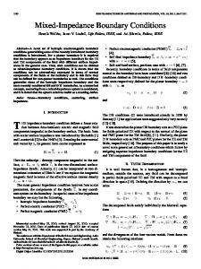
Figure 1. Window function for linear and nonlinear drift model
Ra
Vi
Keywords- Memristor; Memristor-based Oscillator; Nonlinear model Analysis; Memristive-based circuits.
I.
INTRODUCTION
The memristive behavior was experimentally discovered two centuries ago [1] but it wasn't further researched and studied until the year 1971 when professor Chua postulated the existence of the first memristive element ,"the memristor" which relates between the charge and the flux φ [2-3]. HP labs announcement of the invention of the memristor in 2008 [4], led to collecting considerable research interest to use this new element in many applications for example in digital circuits [5-6], analog circuits and oscillators [7-13] in addition to numerous memristor based patents in different areas [14-17]. There are a lot of models for the memristor which discuss the behavior of the memristor with different window functions [18] and with different fractional orders of the differential equation [19]. Here in this work, we will discuss the effect of changing Joglekar’s window function 1 2 1 for linear ion drift model [20]. The effect of changing the dopant value is discussed for nonlinear 1 and linear ∞ as shown in Fig.1. Recently, the first memristor-based oscillator without the usage of any capacitors or inductors was introduced where this circuit basically consists of a single memristor, single resistor and two comparators ANDed together as shown in Fig. 2 [11]. The memristance changes as the current exists within the , . To achieve oscillation, should not range cling to its boundary, therefore we have to make two conditions to control the transition operation which is the
978-1-4673-4810-2/12/$31.00 ©2012 IEEE
Vp
M
Vo
Vn
Vref Figure 2. Memristor-based reactance-less oscillator
reason for the existence of the two comparators. The condition of oscillation of such a circuit is 1 where and represent the maximum and minimum resistance of the memristor respectively, also the set , is the memristance at which reaches , . To trace the circuit operation and for simplicity let 0, assume then the voltage across the memristor is increases until and positive so the memristance respectively then changes its state to reach and so is negative after that decreases until and respectively then will be and so on. reach and This paper is organized as follows: in the next section, the on the oscillation frequency effect of reference voltage and oscillation conditions of linear window function is discussed. In the third section, the effect of nonlinear window on the oscillation frequency and necessary function and and sufficient oscillation conditions is discussed. Finally a discussion and comparison between the two window functions is introduced.
II.
LINEAR-DOPANT DRIFT ANALYSIS
and the voltage across the memristor is given by
In this section, we will discuss the effect of changing and R on the oscillation frequency and the condition of of oscillation in a reactance-less oscillator with linear dopant drift window. By using the model which is proposed in [21-22], where the memristance is given by 2
7 By substituting (6b) into (6a) and integrating from through
2
1
/ , is dopant mobility and where is the memristor’s length. The value of and when 0 are given by: ,
2
9
2
and are the maximum and minimum output where voltage of the AND gate. Therefore, the necessary and and to satisfy (1) sufficient condition for oscillation on can be obtained as:
and the time of negative half cycle is 10 so the frequency of oscillation given by
4 , min
8
after solving the integration, the time of positive half cycle is
3
max
and the duty cycle
1
,
to
are
11
5 2
Figure 3 identifies the region of existence of the oscillatory range increases as behavior where the working increases. When 0 , the working is from 100Ω to 12.66 Ω also at maximum , the working is from 60Ω to 22.79 Ω . Furthermore the minimum could be obtained from (5). When 3 Ω, the circuit will oscillate as in the range 0.4833, . Using the same procedure in [11] to obtain the oscillation frequency, by differentiating (2), the rate of change in the resistance is given by 6
·
2
11
12 As it is clear from (11), the oscillation frequency is a and and is inversely proportional to function of , , . When increases within its range which is specified by (5), the values of and will decrease and hence the frequency of oscillation will increase as shown in Fig. 4. In the 0, the previous equations will be reduced to case of their special cases which are introduced in [11]. To see how the range of the frequency changes as changes assume the memristor parameters are , , , 100Ω, 38 Ω, 10 , 10 and the other , , , 1 , 1 , 0.5 , circuit parameters are 0.75 , For the lowest memristance bound , then should be equal to
, therefore
,
so the maximum oscillation frequency is equal to Figure 3.
Versus ,
for linear dopant model for 38 , 100,1, 1,0.75, 0.5
,
,
,
,
37900 1 2 6
2 6
1 2
13
III.
NONLINEAR-DO OPANT DRIFT ANALYSIS
In this section we will discuuss the effect of changing and on the oscillation freequency and the condition of oscillation for nonlinear dopannt drift window function 4 1 . are given by the same relations The values of in (3), also the necessary and suufficient condition for oscillation on and can be obtaineed as in (4) and (5). As known, the rate of change of the param meter for the HP memristor [4] which represents the ratio betw ween the doped length to the total length of the memristor is
Figure 4. Oscillation frequency verssus
15
16 where the function repressents the nonlinear dopant drift of the memristor behavior. In case c of 1, the system has a linear draft dopant which leadds to the previous case. However 4 1 so the rate of at 1, the window function change is 4 1
Figure 5. Transient Simulation results of linear dopant d model for (upper), (middle) and (lower) for , , , , , and , equal 3 Ω, 38 Ω, 100Ω , 3 , 1 , 2.6 , 1.5 and 2 respectively.
gives
The highest memristance bound where
, and the
, therefore minimum oscillation frequency is 37900 1 380 2
3 6
4 6
2
14
Using the previous parameters, thee maximum and minimum reference voltage are equal 0.4935 and respectively. From Fig. 4 the oscillation frrequency range at 0 is from 0.1969 Hz to 3289 Hzz and at is from 25.78 Hz to 3.701 MH Hz . Figure 4 shows that the oscillation frequeency increases with increasing for any which lies withhin the oscillation range, specified in (4). Furthermore, the osccillation frequency curve of any lies between and curves which correspond to and respeectively. Another advantage of using is that the circuit cann operate under all positive or negative voltages as long as a the oscillation conditions and the voltages sequence are satisfied. Figure 5 shows the output response when all Spice model which voltage parameters are positive using the PS is proposed in [23]. The frequency of osccillation from (10) equals 18.716 Hz which matches the frequenncy obtained from the PSpice simulation.
17
Therefore, 4
1
18
and correspondd to the state variable values of where the memristance and respectively. After integration and performing some simplificcations, the time of positive half cycle is given by
19
4
The time of negative half cycle is calculated by the same formula in (10) and the frequenncy of oscillation is given by 1
20
and the duty cycle is given byy (12). Figure 6 shows that the range of memristance channges from 3 Ω to 4.5 Ω and the oscillation frequency equals 6.476 Hz which matches the range in (4) and a (20) respectively. frequency and In case of grounded , the tim me of positive half cycle is 21
IV.
Due to the behavior of the nonlinear model of the memristor, when the memristorr clings to one of its boundaries or , the oscillation freqquency will be zero as shown in Fig.8(a). But in the case of thhe linear model, the memristor wouldn’t cling to its boundaryy due to the discontinuity of the model as shown in Fig. 8(b).. It is clear that the maximum frequency equals to 290.1 , 31.34 and 8.242 when , equal to 129.5Ω, 0.3V , 148Ω, 0V , and 305Ω, 0.3V respectively for f the nonlinear dopant drift model. However there is no maaximum in the linear model due to the windowing discontinuity effect of the model. Actually the dopant value is unknown due to the variations in the fabrication process butt its value is enclosed between nonlinear dopant 1 andd linear dopant ∞ . For designing a good memristor based b oscillator, the frequency variation range should be veryy narrow as shown from Fig.8 where it is better to work between the first and the second n dopant curves from intersections of linear and nonlinear 4.037 Ω to 12.3 348 Ω in the case 0 curve where the maximum change c in the frequency ∆ 0.2963 .
Figure 6. Transient Simulation results of nonlinearr dopant model for (upper), (middle) and (lower) for , , , , , , and equal 3 Ω, 38 Ω, 100Ω, 3 , 1 , 2.6 , 1.5 and 2 respectively
Figure 7. The oscillation frequency versus
DISCUSSTION N AND COMPARISON
forr different cases of
(a)
and the time of negative half cycle is given byy |
|
22
Therefore the duty-cycle and the perioodic time are D , and 1 (same as linear case)
|V | V
V
respectively and the necessary and sufficieent conditions for oscillation are still the same as in (4) howeveer (5) is simplified to (23) which matches the linear model at 0 [11]. 23 reaches one of the boundaries When the memristance , then the oscillation frequencyy becomes zero as expected. For example, let , , , , , and equal 3 Ω, 38 Ω, 100Ω, 1 , 1 , 0.75 0 and 0.5 respectively. The oscillation frequency will w be equal to 1.788 and the memristance changes frrom 3 Ω to 9 Ω. Figure 7 shows that the curves of the osccillation frequency for different are not enclosed betw ween and curves as in the case of the linear dopant model shown in Fig. 4, due to the nonlinearity of the modell which appears in the oscillation frequency equation (19, 20).
(b)
Figure 8. Oscillation frequencyy versus for different models and 0 (middle) and different 0.3 (upper), 0.3 (lower)
From equations (11) and (221), the oscillation frequency is linearly proportional to the doppant drift mobility which is a physical property of the memristor material so in case of desire of higher frequencies, highly doopant material should be used. A
summary Table of all needed equations to design a memristorbased reactance-less oscillator is introduced in Table I. V.
[10]
CONCLUSION
This paper discusses the oscillation frequency together with the necessary and sufficient conditions of oscillation for linear and nonlinear window models on the memristor based oscillator. From this discussion, the duty cycle, resistance ranges, and conditions of oscillation are functions of the only. However, the oscillation reference voltage frequency is affected by the memristor model where the is smooth in the case of the frequency curve versus nonlinear model. Different circuit simulations are introduced to validate the derived closed formulas. It is pleasure to thank M. Affan Zidan for helpful comments. REFERENCES
[2] [3] [4] [5]
[6]
[7]
[8]
Themistoklis Prodromakis, Themistoklis Prodromakis, and Leon Chua, “Two centuries of memristors,” Nature Materials, vol. 11, no. 6, pp. 478-481, May 2012. L. Chua, “Memristor-the missing circuit element,” IEEE Transactions on Circuit Theory, vol. 18, no. 5, pp.507–519, 1971. L. O. Chua and S. M. Kang, “Memristive devices and systems,” Proc. IEEE, vol. 64, no. 2, pp. 209–223, Feb. 1976. D. B. Strukov, G. S. Snider, and D. R. Stewart, “The missing memristor found,” Nature, vol. 453, no. 7191, pp. 80–83, May 2008. P. O. Vontobel,W. Robinett,P. J. Kuekes,D. R. Stewart,J. Straznicky, and R. S. Williams, “Writing to and reading from a nano-scale crossbar memory based on memristors,” Nanotechnology, vol. 20, no. 42, Oct. 2009. K. Bickerstaff, and E. E. Swartzlander, “Memristor-based arithmetic,” Signals, Systems and Computers (ASILOMAR), 2010 Conference Record of the Forty Fourth Asilomar Conference on , pp.1173-1177, Nov. 2010. K. Witrisal, “A memristor-based multicarrier UWB receiver,” UltraWideband, 2009. ICUWB 2009. IEEE International Conference on , vol., no., pp.679-683, Sep. 2009. T. A. Wey, and S. Benderli, “Amplitude modulator circuit featuring TiO2 memristor with linear dopant drift,” Electronics Letters , vol.45, no.22, pp.1103-1104, 2009. TABLE I.
[11]
[12]
[13]
[14] [15]
ACKNOWLEDGMENT
[1]
[9]
[16] [17] [18]
[19]
[20] [21]
[22]
[23]
Sangho Shin, Kyungmin Kim, and Sung-Mo Kang, “Memristor Applications for Programmable Analog ICs,” Nanotechnology, IEEE Transactions on , vol.10, no.2, pp.266-274, Mar. 2011. A. Talukdar, A. G. Radwan, and K. N. Salama, “Generalized model for memristor-based Wien family oscillators,” Microelectronics Journal vol.42, no. 9, pp. 1032–1038, Sep. 2011. M. Affan Zidan, H. Omran, A. G. Radwan, and K. N. Salama, “Memristor-based reactance-less oscillator,” Electronics Letters, vol.47, no.22, pp.1220-1221, 2011. A. Talukdar, A.G. Radwan and K.N. Salama, “Non Linear Dynamics of Memristor Based 3rd Order Oscillatory System,” Microelectronics journal, vol. 43, no. 3, pp. 169-175, Mar. 2012. A. G. Radwan, K. Moddy, and S. Momani, “Stability and nonstandard finite difference method of the generalized Chua's circuit”, Computers and Mathematics with Applications, vol. 62, pp. 961-970, 2011. G. Snider, “Architecture and methods for computing with reconfigurable resistor crossbars,” U. S. Patent 7203789, 2007. B. L. Mouttet, “Programmable crossbar signal processor,” U.S. Patent 7302513, 2007. G. Sinder, “Molecular-junction-nanowire-crossbar-based neural network,” U.S. Patent 7359888, 2008. B. L. Mouttet “Crossbar control circuit,” U.S. Patent 7609086, 2009. S. Kvatinsky, Eby G. Friedman, Avinoam Kolodny, and Uri C. Weiser, “TEAM: ThrEshold Adaptive Memristor Model,” IEEE Transactions on Circuits and Systems I: Regular Papers (also CCIT Technical Report #804), 2012. M.E. Fouda, A. G. Radwan, “On the fractional-order memristor model,” Journal of Fractional Calculus and Applications, vol. 4, no.1, pp.1-7, Jan. 2013. Y. Joglekar and S. Wolf, “The elusive memristor: Properties of basic electrical circuits,” Eur. J. Phys., vol. 30, no. 4, pp. 661–675, Jul. 2009. A. G. Radwan, M. A. Zidan, and K. N. Salama, "On the mathematical modeling of memristors," Microelectronics (ICM), 2010 International Conference on , pp.284-287, 19-22 Dec. 2010. A. G. Radwan, M. A. Zidan, and K. N. Salama, “HP Memristor Mathematical Model for Periodic Signals and DC,” IEEE International Midwest Symposium on Circuits and Systems (MWSCAS), pp. 861864, Seattle, USA, 2010. Z. Biolek, D. Biolek, and V. Biolková, “SPICE model of memristor with nonlinear dopant drift,” Radioengineering, vol. 18, no. 2, pp. 210 – 214, 2009.
CONTROLLED REACTANCE-LESS OSCILLATOR SUMMARY
Linear window
Nonlinear window 2
2
4
Duty cycle range range Condition of oscillation
max
,
min
,