The addition of the compatibilizer resulted only in a little improvement in ... condensation polymers chemical linkages, arising from transreaction and additional.
Effect of Compatibilization on the Properties of Microfibrillar Reinforced Composites Based on Poly(ethyleneterephthalate) and Polypropylene
O. Evstatiev1, M. Evstatiev2, K. Friedrich1
1) Institut für Verbundwerkstoffe GmbH, University of Kaiserslautern, 67663 Kaiserslautern, Germany 2) University of Sofia, Laboratory on Polymers, 1126 Sofia, Bulgaria
Report for Max Buchner Stiftung Project 2405 August 2005
1
ABSTRACT This report deals with microfibrillar reinforced composites (MFC) based on blends from recycled poly(ethyleneterephthalate) (PET), polypropylene (PP) and a compatibilizer (Orevac CA 100 (O)). They were prepared by melt extrusion and cold drawing. The PET/PP weight ratios amounted to 10/90, 30/70 and 50/50, respectively, with additional O-contents between 0 and 3 wt.%. Rectangular specimens were prepared by injection molding (IM) at processing temperatures below the melting temperatures of PET. Samples of each stage of MFC manufacturing were characterized by means of mechanical testing. The flexural modulus and the flexural strength of the IM MFC-samples are by 50 % better than those of the neat PP. The addition of the compatibilizer resulted only in a little improvement in modulus and strength (relative to the MFC’s without O), but in a clear improvement in the impact energies (up to a compatibilizer fraction of 3%). Key words: microfibrillar reinforced composites, morphology, processing, PET/PP blends, compatibilizer
1. INTRODUCTION The mechanical properties of polymeric materials can often be well improved by blending polyolefins with engineering plastics. However, the partners in most of the polymer blends are thermodynamically immiscible and technologically incompatible. As a result, during processing a large variety of shapes of the dispersed phase can be formed, e.g. spheres or ellipsoids, fibrils or plates [1-3]. Which of these is actually formed depends on the weight ratio of the blend components, their chemical structure, their properties, and the processing conditions. It is well known that shape and size of the dispersed phase strongly affect the properties of the final polymer blend [2, 4, 5]. Processing of an incompatible polymer pair in which the dispersed phase forms in-situ reinforced fibers is the preferable way to achieve the highest mechanical properties. In order to obtain such a structure, a new type of processing route, the so-called microfibrillar reinforced composite (MFC) concept was created about ten years ago [6-8]. The preparation of MFC includes three basic steps: (i)
melt blending with extrusion of two immiscible polymers having different melting temperatures Tm (mixing step);
(ii)
cold drawing of the extrudate with good orientation of the two phases (fibrillization step);
2
(iii)
thermal treatment at a temperature between the Tm`s of the two blend partners (isotropisation step).
While during the second step the two polymers are converted into a highly oriented state, i.e. one deals with an oriented blend [9], the third step results in melting of the lower melting component and its transformation into an isotropic matrix, reinforced with the microfibrils of the higher melting component. Technologically, this transition to an MFC structure can take place during processing of the drawn blend via injection- or compression molding. The essential requirement is that the processing window is not too close to the Tm of the microfibrils, otherwise they will melt and return into a spherical shape. Obviously two important factors typical for composite materials contribute to a good mechanical property profile: (i) a higher aspect ratio, and (ii) a good adhesion between the matrix and the reinforcing phase. In fact, it was demonstrated that in the case of MFC from condensation polymers chemical linkages, arising from transreaction and additional condensation reactions, improve the adhesion between the two components [6-9]. In the cases where chemical interactions are not possible, a strong nucleation effect of microfibrils on the matrix crystallization, i.e. the formation of transcrystallization layers can sometimes help to strengthen the fiber/matrix adhesion. The
objective
of
the
present
study
was
to
demonstrate
these
effects,
using
polyethyleneterephthalate (PET) and polypropylene (PP) as the blend partners, along with a special type of compatibilizer to chemically improve the interaction between the two blend components. 2. EXPERIMENTAL Materials Recycled PET (type FR 65, with a melting range of 236-252oC, supplied by Rethmann Plano GmbH, Germany) (as a reinforcing component) and commercial grade Polypropylene (PP) (type Novolen with MFI 5, provided by Basell, Germany) (as a matrix) as well as a compatibilizer (Orevac CA 100, Atofina 1) were used. Orevac CA 100 is a chemically functionalized polypropylene with a high content of maleic anhydride. Grafting on polypropylene backbone is achieved with a new processing technology, which allows to optimise the compromise between chain breakdown and grafting efficiency. 3
Grafted maleic anhydride induces polarity to polypropylene and so outstanding adhesion properties on glass fibers and mineral fillers. The Orevac CA 100 has been specially developed as coupling agent for glass fiber or mineral filled polypropylene (Table 1). PROPERTY
TEST METHOD
UNIT
VALUE
(190°C, 325 g)
g/10 mn
10
DSC
°C
167
ISO 306 (9,81 N)
°C
147
Flexural Modulus
ISO 178
MPa
880
Tensile properties
ISO 527-2
Strength at yield
MPa
22
Strength at break
MPa
22
%
12
Melt flow index Melting point Vicat point
Elongation at break Table 1: Special Characteristics of Orevac CA 100.
Compounding can be achieved on conventional equipments such as monoscrews, twinscrews or kokneaders with usual temperatures. Processing and Sample Preparation Pellets of PET, PP and Orevac (O), dried at 80°C, were mixed in a twin-screw extruder “Brabender”, using different weight ratios. The temperature profile, starting from the feeding zone to the die, was 260, 270, 260 and 245°C, and the screws rotating rate was maintained at 30 rpm. The extrudate was cooled down to a temperature of 75-80°C and continuously drawn by a self-designed drawing device, allowing a take up rate of about 100 m/min, which corresponds to a draw ratio of about 8-11. The isotropization step of MFC preparation (melting of the PP and its transformation into an isotropic matrix reinforced with PET microfibrils) was realized during injection molding processing on a lab-scale machine, “Babyplast“– produced by “Cronoplast S.L”. – Barcelona, at a temperature between Tm of PP and PET. For comparison, injection molding of the pellets from the drawn blends was performed also at a temperature higher than Tm of PET. Rectangular testing samples with dimensions of 4x10x80 mm3 were produced. 4
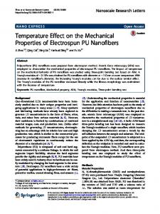
3. MECHANICAL PROPERTIES 3.1. Mechanical Testing Mechanical tests (three point bending (3PB) test) of the injection molded blends were performed at room temperature and a crosshead speed of 5 mm/min, using a Zwick 1464 testing machine. Impact tests were done on a Charpy impact-testing machine, produced by “CEAST Impact Pendulums Development”, Italy (pendulum mass of 2.19 kg, diameter of 0.3738 m and speed of 3.7 m/s). 3.2 Flexural Properties The flexural moduli of IM samples containing an MFC structure are about 50 % higher than those measured for the neat PP (Fig. 1a). This improvement becomes slightly better, when more of the compatibilizer is involved in the MFC structured samples. Concerning the flexural strength values (Fig. 1b), a similar tendency as for the flexural modulus could be observed. A slight increase of the strength for the samples possessing a certain lower amount of compatibilizer became evident.
Flexural Modulus of Injection Molded MFC- Structured PET/PP Blends With and Without Compatibilizer
Flexural Strength of Injection Molded MFC- Structured PET/PP Blends With and Without Compatibilizer
2,5
FLEXURAL STRENGTH [MPa]
FLEXURAL MODULUS [GPa]
60
PA6
2
1,5
HTPA
1
0,5
HTPA/PA6 50/50 ex
50 40
30 20
10
0 PE T/ PP /O PE 10 T/ /9 PP 0/ 0 /O PE 10 T/ /8 PP 9/ 1 /O PE 10 T/ /8 PP 8/ 2 /O 10 /8 7/ 3 PE T/ PP /O PE 30 T/ /7 PP 0/ 0 /O PE 30 T/ /6 PP 9/ 1 / O PE 3 0/ T/ 68 PP /2 /O 30 /6 7/ 3 PE T/ PP / O PE 5 0 T/ /5 PP 0/ 0 /O PE 50 T/ /4 PP 9/ 1 /O PE 5 0/ T/ 48 PP /2 /O 50 /4 7/ 3
PP
PP
PE T/ PP /O PE 1 T/ PP 0/90 /0 /O PE 10 T/ /8 PP 9/ /O 1 PE 1 T/ PP 0/8 8/ /O 2 10 /8 7/ 3 PE T/ PP /O PE 3 T/ PP 0/7 0/ /O 0 PE 3 T/ PP 0/69 /1 / O PE 3 T/ 0/ PP 68 /2 /O 30 /6 7/ 3 PE T/ PP /O PE 5 T/ PP 0/5 0/ /O 0 PE 5 T/ PP 0/49 /1 /O PE 5 T/ PP 0/4 8/ /O 2 50 /4 7/ 3
0
HTPA/PA6 50/50 dr
Institut für Verbundwerkstoffe GmbH, RL
1
Institut für Verbundwerkstoffe GmbH, RL
2
Fig. 1. Flexural properties of injection molded PET/PP/O blends (a) flexural modulus
(b) flexural strength.
3.3 Impact Properties All of the samples used for the impact testing procedure were notched (ISO 1791/eU). The corresponding diagram (Fig. 2) shows an increase in impact energy of the injection molded samples with an increasing amount of compatibilizer. Fehler! Es ist nicht möglich, durch die Bearbeitung von Feldfunktionen Objekte zu erstellen. 5
Fig. 2 Impact energy of injection molded PET/PP/O blends. In case of the MFC-samples with the lowest amount of PET-microfibrils (10 wt%), the values were also clearly higher than the one measured for the neat PP. This was even still the case when the PET content was increased to ca. 30 wt%, although here the absolute values were already lower than those of the 10% PET-samples. Only if the PET-content was raised to 50%, the impact energies slightly dropped below the neat PP-value. 4. CONCLUSIONS From the above results and discussion the following conclusions can be deduced: •
MFC-structures could be successfully achieved with PET/PP blends following the proposed industrial relevant line. The peculiarity of MFC offers the opportunity to use this approach for recycling purposes.
•
The MFC-structure could be preserved even after injection molding, although the orientation of the fibrils was random. The flexural strength and modulus of the blends were superior to those of the neat PP. This fact demonstrates the reinforcing effect of the PET fibrils.
•
The values of the flexural tests and of the impact tests could be further improved if a compatibilizer of the type OREVAC CA 100 was added to the PET/PP-blends. The positive effects by the use of this compatibilizer has also been found in other applications, using glass fibers as reinforcements in a PP matrix [10].
ACKNOWLEDGEMENT Orlin Evstatiev is grateful to the Max-Buchner-Foundation for his fellowship under Ref. Nr. 2405. REFERENCES 1. A. Leclair, B. D. Favis, The Role of Interfacial Contact in Immiscible Binary Polymer Blends and its Influence on Mechanical Properties, Polymer, 37, 4723 (1996). 2. D. R. Paul, C. B. Bucknall, Polymer Blends, vol. 2. John Wiley and Sons, New York, USA, (2000). 3. J. Li, B. D. Favis, Characterizing Co-continuous High Density Polyethylene/ Polystyrene Blends, Polymer, 42, 5047 (2001).
6
4. M. A. Huneault, Z. H. Shi, L. A. Utracki, Development of Polymer Blends Morphology During Compounding in a Twin-Screw Extruder. Part IV: A New Computational Model with Coalescence. Polym. Eng. Sci., 35, 115 (1998). 5. N. P. Cheremisinoff, Handbook of Engineering Polymeric Materials. Marcel Dekker, New York, USA (1999). 6. M. Evstatiev, S. Fakirov, Microfibrillar Reinforcement of Polymer Blends, Polymer, 33, 877 (1992). 7. S. Fakirov, M. Evstatiev, S. Petrovich, Microfibrillar Reinforced Composites from Binary and Ternary Blends of Polyesters and Nylon 6, Macromolecules, 26, 5219 (1993). 8. S. Fakirov, M. Evstatiev, Microfibrillar Reinforced Composites-New Materials from Polymer Blends. Adv. Mat, 6, 395 (1994). 9. S.M. Aharoni, Microfibrillar-Reinforced Nylon-6/PET Fibers with Interfacial Bonding, Intern. J. Polymeric Mater, 38, 173 (1997). 10. Oravec CA 100: MAH Functionalized PP, Atofina, Internet Presentation, February 1, 2001.
7