Mar 26, 2010 - used to imprint a vortex on the condensate arising from the polariton optical ... The vortex core radius is found to decrease with increasing pump ...
PRL 104, 126402 (2010)
PHYSICAL REVIEW LETTERS
week ending 26 MARCH 2010
Effect of Interactions on Vortices in a Nonequilibrium Polariton Condensate D. N. Krizhanovskii,1 D. M. Whittaker,1 R. A. Bradley,1 K. Guda,1 D. Sarkar,1 D. Sanvitto,2 L. Vina,2 E. Cerda,3 P. Santos,3 K. Biermann,3 R. Hey,3 and M. S. Skolnick1 1
Department of Physics and Astronomy, University of Sheffield, Sheffield, S3 7RH, United Kingdom 2 Departmento Fisica de Materiales, Universidad Autonoma de Madrid, 28049 Madrid, Spain 3 Paul-Drude-Institut fu¨r Festko¨rperelektronik, Berlin, Germany (Received 4 June 2009; published 26 March 2010)
We demonstrate the creation of vortices in a macroscopically occupied polariton state formed in a semiconductor microcavity. A weak external laser beam carrying orbital angular momentum (OAM) is used to imprint a vortex on the condensate arising from the polariton optical parametric oscillator (OPO). The vortex core radius is found to decrease with increasing pump power, and is determined by polaritonpolariton interactions. As a result of OAM conservation in the parametric scattering process, the excitation consists of a vortex in the signal and a corresponding antivortex in the idler of the OPO. The experimental results are in good agreement with a theoretical model of a vortex in the polariton OPO. DOI: 10.1103/PhysRevLett.104.126402
PACS numbers: 71.36.+c, 42.65.Yj, 78.20.Bh
Microcavity polaritons are bosonic quasiparticles, which arise from strong exciton-photon coupling in semiconductor microcavities. Characteristic bosonic phenomena, such as stimulated scattering [1] and polariton condensation have been reported [2]. In contrast to well-known atom Bose-Einstein condensates (BEC), polariton condensates are intrinsically out of equilibrium: a balance is reached between external excitation and losses due to the finite polariton lifetime [3,4]. In this respect the system has similarities to a laser, but with the fundamental difference that the particles have hybrid light-matter character with strong interactions due to the excitonic component. Nonequilibrium dynamics can lead to a much richer phenomenology of spontaneous pattern formation than in equilibrium systems [5], with vortices a typical example. Vortices are found in many areas of science, including particle physics, optics, and condensed matter systems. They are characterized by winding of phase around a point, the vortex core, where the density of the system goes to zero. The total phase change for a complete loop must be an integer multiple of 2�, so a vortex is a state with quantized orbital angular momentum (OAM). Vortices have been intensively studied in classical systems including optical vortex beams [6] and lasers [7]. They are also a characteristic property of condensed-phase systems like BEC, liquid helium, and superconductors [8]. Spontaneous formation of vortices has been observed in an incoherently pumped polariton system [9]. In this Letter we demonstrate that vortices in a polariton condensate can be created using a weak external imprinting beam (which we term the im beam). We find that the vortex core radius is determined by polariton-polariton interactions and show that these lead to a decrease of the radius with increasing particle density. Here, the low polariton mass (�10�5 me ) plays an important role; the polariton vortex radius is typically �10 �m, some 2 orders of magnitude larger than in an atom system. This enables us to observe in 0031-9007=10=104(12)=126402(4)
situ the vortex profile and its density dependence, unlike in atom BEC experiments where vortices can only be imaged following condensate expansion [10], which is a destructive technique. The system we study is a microcavity optical parametric oscillator (OPO) [1], in which coherent high density signal (s) and idler (i) states (condensates) arise from polaritonpolariton scattering from the pump (p), as shown in Fig. 1(a). An important property of the OPO is that the phase of the signal and idler are not determined by that of the pump [11], but appear as a spontaneous symmetry breaking at the OPO threshold, similar to the phase transition of a thermal equilibrium BEC. Both the OPO modes and the polariton condensate which is realized by nonresonant pumping [2] exhibit characteristic properties of a system possessing a macroscopic wave function, such as extended spatial and temporal coherence [2,12–14]. As well as vortex creation, we demonstrate OAM conservation in the parametric scattering process; this means that when a vortex is imprinted onto the OPO signal, polariton-polariton scattering results in an antivortex with opposite OAM in the idler, as has been predicted previously theoretically [15]. It is this vortex-antivortex pair that is created in our experiment. We show theoretically that when the signal population is small compared to the pump, which is the regime of the present experiments, the signal and idler vortices have identical profiles, determined by the interactions. The experiments were carried out at 4 K on a GaAsbased microcavity grown by molecular beam epitaxy. It has a Rabi splitting of 6 meV and zero detuning between the quantum well exciton and the optical mode. A single mode Ti-Al2 O3 laser on resonance with the lower polariton branch at 14� was used to excite the OPO [Fig. 1(a)]. The zero OAM pump was focused to a �50 �m Gaussian spot. A spatial light modulator was used to generate a GaussLaguerre optical beam, corresponding to an optical vortex
126402-1
Ó 2010 The American Physical Society
PHYSICAL REVIEW LETTERS
Energy
PRL 104, 126402 (2010) idler
a)
b)
c)
signal
im-beam
pump mp=0
signal
10 µm
15 µm
k-vector 1
Imprinting beam at k-signal
m=+1 beam at k-idler
f)
d)
signal
signal + im-beam
A B
B
A
7 µm
g)
e) A
A
0
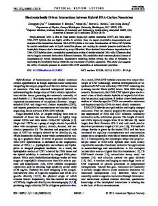
FIG. 1 (color online). (a) Schematic diagram of OPO. (b) Real space image of the signal with no imprinting beam. (c) Image of Gauss-Laguerre imprinting beam (im beam). (d) Signal with weak im beam of (c), showing an imprinted vortex labeled A. (e) Interferogram revealing the 2� phase variation around the vortex of (d). (f) Vortex in signal, labeled A, created by excitation at the idler position with Gauss-Laguerre beam. (g) Interferogram revealing the vortex with OAM ms ¼ �1 created in (f). The red lines are cross sections through the vortex cores of (c) to (d), with the sizes of the cores (FWHM) indicated.
with OAM M ¼ 1 which was used as the imprinting beam. Figure 1(b) shows the spatial image of the OPO signal emission, which occurs at 1.533 eV and has a linewidth of 100 times weaker than the signal [14] due to the small photonic component at the idler, making it impossible to obtain spatial and interference images. However, we are able to show that the pair scattering leads to the creation of vortex antivortex pairs. Using a pump power just below the OPO threshold, we apply a beam with OAM M ¼ þ1 at the angle and energy where the OPO idler would appear. The ‘‘signal’’ then forms at k � 0 due to pair scattering from the pump, stimulated by the probe beam. In this geometry, we are able to perform the required imaging of the signal; the vortex image and the corresponding self-interference image are shown in Figs. 1(f) and 1(g), respectively. A dip in intensity is observed in Fig. 1(f) corresponding to a
(a)
(b)
4 -1/2
6
signal idler
1
signal idler pump
2
0.5
√nsni=0.01 np √nsni=np 0
0
2
4 -1/2
r/(2Mcκ√nsni)
0
0.5
1
vortex radius/(2Mcκnp)
c)
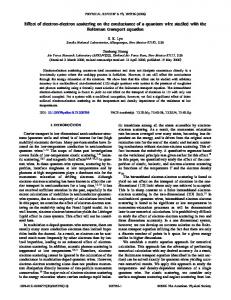
vortex core. In Fig. 1(g) a fork dislocation corresponding to a vortex labeled A in Fig. 1(f) is observed, pointing to the right rather than to the left as for the vortex labeled A in Figs. 1(d) and 1(e), proving that the OAM is ms ¼ �1. Here, in Fig. 1(f) we image the same original (uninverted) beam as in Fig. 1(d). In order to obtain a better understanding of the nature of the vortex, we have developed a theoretical model of a vortex in a �ð3Þ OPO. Our treatment starts from the classical model of an OPO with uniform fields for pump, signal, and idler [18], and adds a vortex antivortex pair to the signal and idler, which locally modulates the fields in the region of the core. The modulation functions are determined by a set of coupled nonlinear differential equations, which we solve numerically. Details of the theory will be presented elsewhere. Figure 3(a) shows typical profiles calculated for the pffiffiffiffiffiffiffiffiffi pffiffiffiffiffiffiffiffiffi three modes at low ( ns ni ¼ 0:01np ) and high ( ns ni ¼ np ) signal intensities. Here np is the polariton density in the pump, which is nearly constant above threshold [18]. The calculation uses structural parameters appropriate to the experimental microcavity. The length scale in the plot pffiffiffiffiffiffiffiffiffi is the healing length � ¼ ð2Mc � ns ni Þ�1=2 . At small pffiffiffiffiffiffiffiffiffi pump powers when ns ni ¼ 0:01np the signal and idler profiles are identical with radii of ��, and the pump is unaffected by the vortex. At high powers, the signal and idler profiles separate, with the idler having the smaller core, and a ‘‘bump’’ appears in the pump in the core region, where it is less depleted by the OPO process. The separation is shown in more detail in Fig. 3(b), where the vortex pffiffiffiffiffiffiffiffiffi radii are plotted as a function of ns ni =np . In this figure, the length scaling used is ð2Mc �np Þ�1=2 , to show explicitly the strong dependence on population. The behavior can be understood using physical arguments based on the competition between the blueshift due to polariton-polariton interactions and the OPO scattering process arising from the nonlinearity [18]. The blueshift provides restoring forces which control the vortex radius,
2
a) 0.9 kW/cm2
P (kW/cm2) 1 2 3 4
|g(r)|
0
1
week ending 26 MARCH 2010
PHYSICAL REVIEW LETTERS
PRL 104, 126402 (2010)
0
√nsni/np
FIG. 3. (a) Calculated signal (solid line), idler (square), and pump (dot) vortex profiles for signal and idler populations near threshold (black), and comparable to the pump (gray). (b) Variation of signal (solid line) and idler (square) core radii with signal or idler population. The dashed line is obtained from the near-threshold approximation equation (1).
126402-3
PRL 104, 126402 (2010)
PHYSICAL REVIEW LETTERS
as in the standard Gross-Pitaevskii equation [8]. It tends, at high powers, to produce different radii for the signal and idler because of the different masses; the more excitonic idler has a larger mass and so a smaller core. The OPO effect, by contrast, tries to make the profiles the same, because the OPO scattering is a local process, generating equal numbers of signal and idler polaritons at a given point in space. The regime when the signal (and idler) population is much smaller than that in the pump (ns � 109 – 1010 cm�2 � 0:2np ), is the one which is accessed in the present experiment [14]. In this case the OPO process dominates and the signal and idler profiles are locked together. The actual profile, gðrÞ, is, however, still determined by the blueshift terms; we can show that it satisfies an equation of the complex Ginzburg-Landau (CGL) type. Scaling the radius by the healing length �, we find � � m2 r2r � 2 g ¼ �ðjgj2 � 1Þg; (1) r where � is a complex constant with magnitude of order unity. It is determined by the ratio of the signal and idler linewidths, the exciton and cavity amplitudes (Hopfield factors) for the modes, and the phase difference � ¼ 2�p � �s � �i between the pump, signal, and idler phases, respectively. The solutions of this equation provide the dashed curve on Fig. 3(b), which is in very good pffiffiffiffiffiffiffiffiffi agreement with the full theory for ns ni & 0:1np . We note that a CGL equation of the same form is obtained for the incoherently pumped polariton condensate [19]. Although the OPO is a more complicated system, with three coherent fields, in the near-threshold regime it displays similar physics. In weak coupling microcavity lasers (VCSELs), which operate at 1 to 2 order of magnitude higher electron-hole density than the polariton condensate, there is also an effective �ð3Þ nonlinearity due to saturation of the gain [7]. This contrasts with the direct interactions between polaritons due to their exciton component. At low powers the VCSEL can be approximated by a CGL type equation similar to Eq. (1), and hence a decrease of vortex size with power is expected. However, the variation is expected to be more complicated as saturation is approached. A typical vortex size of several microns is observed in Ref. [7], but the physical origin of this is not discussed. To the best of our knowledge there have not been any studies on the variation of vortex size with pump power in VCSELs. Instead as the current density was increased in Ref. [7], spontaneous vortex proliferation was observed. It is also interesting to compare the magnitudes of the vortex radius in the polariton and atom systems: for polarpffiffiffiffiffiffiffiffiffi itons, Mc � 10�5 me , and � ns ni � 10�1 meV. Equivalent values for a rubidium BEC with a density n � 1014 cm�3 would be M � 105 me and gn ¼ 4�as n@2 =M � 10�7 meV, where the atom scattering length as � 5 nm [8] and g is the atom interaction strength. This gives radii
week ending 26 MARCH 2010
for the polariton and the atom systems of order 10 and 0:1 �m, respectively. We see that the much smaller polariton mass compensates the stronger interactions, giving a healing length 2 orders of magnitude greater than atom BECs. To conclude, the polariton OPO supports a novel excitation consisting of a vortex in the signal and an antivortex in the idler. We have shown that the core radius of vortices in the polariton condensate is determined by polaritonpolariton interactions. With ultrafast measurement techniques the imprinting method also provides a means to investigate vortex dynamics on time scales inaccessible in other systems. By including polarization as well as phase variation in the imprinting beam, it should be possible to study more complicated topological defects, such as ‘‘halfvortices’’ [20]. This work was supported by Grants EP/G001642, EP/ E051448, MEC MAT2008-01555/NAN, QOIT-CSD200600019, CAM S2009/ESP-1503, FP7 ITNs ‘‘Clermont4’’ (235114), and ‘‘Spin-Optronics’’ (237252). We thank M. Wouters, Z. Hadzibabic, and K. Burnett for helpful discussions.
[1] R. M. Stevenson et al., Phys. Rev. Lett. 85, 3680 (2000). [2] J. Kasprzak et al., Nature (London) 443, 409 (2006); R. Balili et al., Science 316, 1007 (2007); Hui Deng et al., Phys. Rev. Lett. 99, 126403 (2007); A. Amo et al., Nature (London) 457, 291 (2009). [3] M. Wouters and I. Carusotto Phys. Rev. Lett. 99, 140402 (2007). [4] D. N. Krizhanovskii et al., Phys. Rev. B 80, 045317 (2009). [5] M. C. Cross and P. C. Hohenberg, Rev. Mod. Phys. 65, 851 (1993). [6] L. Allen et al., Phys. Rev. A 45, 8185 (1992). [7] J. Scheuer and M. Orenstein, Science 285, 230 (1999). [8] See, e.g., L. Pitaevski and S. Stringari, Bose-Einstein Condensation (Oxford University Press, Oxford, 2003). [9] K. G. Lagoudakis et al., Nature Phys. 4, 706 (2008). [10] M. R. Matthews et al., Phys. Rev. Lett. 83, 2498 (1999); K. W. Madison et al., Phys. Rev. Lett. 84, 806 (2000). [11] M. Wouters and I. Carusotto, Phys. Rev. A 76, 043807 (2007). [12] A. Baas et al., Phys. Rev. Lett. 96, 176401 (2006). [13] A. P. D. Love et al., Phys. Rev. Lett. 101, 067404 (2008). [14] D. N. Krizhanovskii et al., Phys. Rev. Lett. 97, 097402 (2006). [15] D. M. Whittaker, Superlattices Microstruct. 41, 297 (2007). [16] D. Sanvitto and D. N. Krizhanovskii et al., Phys. Rev. B 73, 241308(R) (2006). [17] M. Martinelli et al., Phys. Rev. A 70, 013812 (2004); D. P. Caetano et al., Phys. Rev. A 66, 041801(R) (2002). [18] D. M. Whittaker, Phys. Rev. B 63, 193305 (2001); D. M. Whittaker, Phys. Rev. B 71, 115301 (2005). [19] J. Keeling and N. G. Berloff, Phys. Rev. Lett. 100, 250401 (2008). [20] Y. G. Rubo, Phys. Rev. Lett. 99, 106401 (2007).
126402-4