Accepted 10 January 2014, Available online 01 February 2014, Special Issue-2, (February 2014). Abstract ... maximum tensile force at the wall of the semi-drawn cup. In order to .... general scenario, by increasing the n value, the formability.
International Journal of Current Engineering and Technology E-ISSN 2277 – 4106, P-ISSN 2347 - 5161 ® ©2014 INPRESSCO , All Rights Reserved Available at http://inpressco.com/category/ijcet
Research Article
Effect of Mechanical Properties on Deep Drawing Formability Prediction U. PranaviȦ*, P. Venkateshwar ReddyȦ, K. LavanyaȦ, NV Narasimha CharyuluȦ and Perumalla Janaki RamuluȦ Ȧ
Department of Mechanical Engineering, Vardhaman College of Engineering
Accepted 10 January 2014, Available online 01 February 2014, Special Issue-2, (February 2014)
Abstract In the present study the effect of mechanical Properties like strain hardening coefficient (n) and yield strength (σys) on the deep drawing formability is observed. In which three levels of n and σ ys have been considered. All the simulations were performed in the PAM STAMP 2G a FEM code and specialized sheet metal forming soft. Hill’s 1948 isotropic hardening yield criterion was used as the plasticity model. Hollomon’s power law was used as the strain hardening law. All three levels of mechanical properties were taken from experimental work of Singh and Gupta (2010) on IF steel. The data like dome height, and thickness distribution variations is taken. The results showed that dome height for the all the simulation is same and thickness distribution has got little variation with respect to mechanical properties. Keywords: Sheet metal forming, Deep drawing, simulation, formability, dome height, thickness distribution.
*Corresponding author: U. Pranavi
possibility of FE analysis-based optimization in a highly nonlinear process, such as the multi-stage deep drawing process and their procedure used there can be applied to other nonlinear processes, which generally, have numerous local optima and require FE analysis for single stage simulation. Kim and Hong (2007) studied circular cup deep drawing of a molybdenum sheet was investigated to evaluate the effect of die design variables using finite element (FE) analysis. Then, optimization, with respect to the die design variables, was conducted to find the most reliable multi-stage process using FE simulation, to evaluate the objective function value. Jawad et al (2008) studied the effect of varying punch nose radius used in deep drawing operation by using a commercially finite element program code ANSYS 5.4, for the numerical simulation of the deep drawing operation, and the numerical results were compared with the experimental work and concluded that frictional force is applied to the metal largely by the edge of the punch and not by its flat section and the value of work required to form apart with large nose radius are much more than the value required to form apart with small punch nose radius. Hama et al in the year 2008 examined the effect of tool-modeling accuracy by using finite-element simulation on a square-cup deep-drawing process and by using the quadratic parametric surfaces proposed by Nagata (Nagata patch) for tool surface and in case of the present deepdrawing model, the total number of tool elements can be reduced to about 10% of that of the polyhedral model using the Nagata patch model. Rodrigues et al (2009) made a multi-step analysis for determining admissible blank-holder forces in deep-drawing operations for stamping friction stir welded tailored blanks and
DOI: http://dx.doi.org/10.14741/ijcet/spl.2.2014.55
303 | International Conference on Advances in Mechanical Sciences 2014
1. Introduction 1
Deep drawing is a one of the methods of forming under compressive and tensile conditions whereby a sheet is transformed into a hollow cup, or a hollow cup is transformed into a similar part of smaller dimensions without any intention of altering the sheet thickness. The deep-drawing process is simply and widely used in the industry, but it produces cups at limited drawing ratios, which does not exceed the ratio of 2.2 because of the drawing resistance from the flange portion and the maximum tensile force at the wall of the semi-drawn cup. In order to increase production efficiency and obtain goodquality parts, many techniques have been adopted to achieve a higher drawing ratio. There are many studies carried out on numerical simulations of deep drawing process in which few of them are discussed here. Meinders et al (2000) simulated on the deep drawing of two products using Tailored Blanks are discussed and the correlation between the experimental results and the simulation results found to be satisfactory. Padmanabhan et (2007) examined the effect of anisotropy in the tailorwelded blank and the orientation of blank sheets rolling direction during deep-drawing process and made analysis on deep-drawing mild steel and dual-phase steel tailorwelded blank models and carried out by using FE code DD3IMP; It was observed that the punch force required for deep-drawing increases with anisotropy in the blank sheets. The strength difference and the initial anisotropy induce uneven metal flow during deep-drawing and showed a significant improvement in the formability of tailor-welded blanks. Kim et al (2007) showed the
U. Pranavi et al
International Journal of Current Engineering and Technology, Special Issue-2 (Feb 2014)
Table 1 Base material (interstitial free steel) properties used for simulation (Singh and Gupta (2010)) Base
E (GPa)
γ
σYS*(MPa)
Base
210
0.33
143 550 0.2811 1.75 * obtained from flow equation σ = K εn
K (MPa)
n
R0
R45
R90
1.5
3.06
t (mm) 1.3
previewed the formability behavior of tailored welded blanks (TWBs) by joining two aluminium alloys, the AA 5182-H111 and the AA 6016-T4 alloys, in similar and dissimilar combinations. Analytical FLDs were plotted, for both the base materials by using a theoretical stress based criteria and principal strains in the cup walls, obtained in the numerical simulation of deep-drawing tests performed with different BHF values and compared with the formability limits established by the FLDs. And they concluded that this procedure is used to determine the maximum BHF for deep drawing for the different TWBs. Majd et al (2011) studied the back-propagation artificial neural network (BPANN) with Levenberg–Marquardt algorithm to predict the limiting drawing ratio (LDR) of the deep drawing process and prepare a training set for BPANN and that program will be able to estimate the LDR for any new given condition and by comparing both FEM and BPANN results, an acceptable correlation was found. Arab et al (2013) analyzed the deep drawing of axisymmetric cylindrical cup by using rigid viscoplastic FEM and ABAQUES software with anisotropic Hill’s non-yield criterion and found that the satisfactory experimental validation of the numerical prediction has been achieved for deformation stages and thickness distributions on the sheet and , he mentioned that close cooperation between experienced die designers and FEM engineers makes simulation a practical tool for designing progressive and transfer dies. From the above literature, many of studies are based on the deep drawing process and effect external parameters on the process and their results. The present study is focused on effect of mechanical parameters on the sheet formability prediction during the deep drawing process and also their sensitivity on cup dome height and thickness distribution is seen.
The base material sheet comprised of quadrilateral shell elements of Belytschko-Tsay formulation with five through thickness integration points. Hill’s 1948 isotropic hardening yield criterion was used as the plasticity model. Hollomon’s power law (σ = Kεn, where σ is true stress, K is the strength coefficient, ε true strain and n is the strain-hardening exponent) was used as the strain hardening law. The base material sheet size of 200×200 mm was simulated for all the conditions and mechanical properties were taken from experimental work of Singh and Gupta (2010) as tabulated in Table 1.
2. Methodology
3. Results and Discussion
The tools required for test punch, die, blank holder, draw bead and blank were generated in Solid works, a CAD package, and meshed using Delta Mesh facility in PAM STAMP 2G.
The effect of strain hardening coefficient (n) and yield strength (σys) on dome height is noted for all the simulations. The dome height is measured based on the failure happened at the punch travel progression with help of Auto Keeler’s theory which is inbuilt theory in the PAM STAMP 2G and generates the forming limit diagram (FLD) showing forming limit curve (FLC). The FLC separates the failure strains and safe strains.
Table 2 Varied Mechanical properties for simulation (Singh and Gupta (2010)) Mechanical Properties Strain hardening coefficient (n) Yield strength (σys) MPa
Considered Value for simulation 0.2811 0.2553 0.2577 143.8 134.7 130.9
A uniform mesh size of 1 mm was used throughout the simulations. Friction coefficient “µ” was assumed to be 0.15 and is kept constant throughout the study. Blank Holder Force (BHF) 25 kN was chosen to avoid wrinkling and extra thinning. Downward stroke is given to the punch with a velocity of 10 mm/min. In total, 6 simulations were performed by varying the strain hardening coefficient (n) and yield strength (σys) at three levels as tabulated in Table 2. From the simulation results, dome height and thickness distribution were evaluated. The effect of n and σys on dome height and thickness distribution was noted.
3.1 Deep drawn cup Dome height and failure initiations
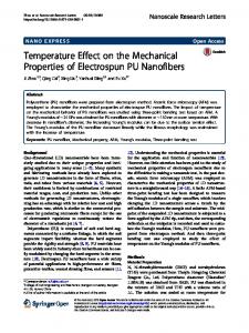
Fig. 1 Assembly of Deep drawing set up setup in PAM STAMP 2G along with blank
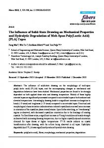
It is observed that in the all the simulations, failure is observed at the progression state of 24 irrespective of other mechanical properties. So, deep drawn cup dome height is taken as 24 mm directly. Figure 2 shows the dome height of 24 mm of blank for n=0.2577, similarly for 304 | International Conference on Advances in Mechanical Sciences 2014
U. Pranavi et al
International Journal of Current Engineering and Technology, Special Issue-2 (Feb 2014)
other cases also observed. The failure initiations were same in the six simulations.
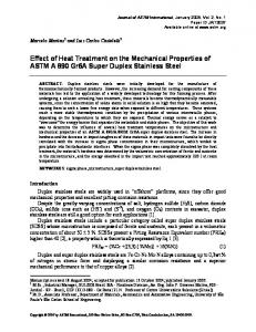
observed that by increasing the σys from 130.9 to 143.8 MPa the thinning distribution is increased. The more thickness distribution is seen in for 143.8 MPa. This leads, by increasing the yield strength of the material the formability will come down. Conclusions
Fig. 2 Dome height of blank for n=0.2577 3.2 Thickness distribution The thickness distribution of blank at different strain hardening coefficient (n) and yield strength (σys) is measured by plotting perpendicular plane to failure location. The effect of n and σys is seen on thickness distribution as shown in Fig. 3 a & b.
References
5
Thickness (mm)
0 0
50
100
150
200
-5
n=0.2577
-10
n=0.2533
-15
n=0.2811
-20 Distance from one end the sheet along the major straining direction (mm)
-25
5
Thickness (mm)
0 -5
0
50
100
150
200
-10 -15 -20
ys=13 0.9
-25 -30 -35
From the present work, the following conclusions have been drawn. The dome height of deep drawn cup variation almost same for all six cases and obtained as 24 mm. The failure initiation is happened at same places in the cup. The effect of n is very less with respect to thickness distribution than σys. By increasing the σys the thickness distribution also increased, whereas reverse for n. The formability prediction is also depends on many parameters like material thickness, types of material and mechanical properties. By changing one or two parameters perfect prediction cannot be decided.
Distance from one end the sheet along the major straining direction (mm)
Fig. 3 (a & b) Thickness distributions for different values of n and σys From the Fig. 3 (a), it is understood that the effect of the n on the thickness distribution is not much. At n=0.2533 has got less thinning distribution than at 0.2577 and 0.2811. In general scenario, by increasing the n value, the formability will be more and less thinning will takes place. But in this case, even n value 0.2811 more, thinning distributions got more than 0.2533. This means, just because of n value formability will not improve; it is synergic effect of other parameters also. Similar manner, the effect of σys on thickness distribution is shown in the Fig. 3 (b). It is
T. Meinders, A. van den Berg, J. Huetink, (2000), Deep drawing simulations of Tailored Blanks and experimental verification, Journal of Materials Processing Technology 103, 65±73. Emil Evin, Jana Tkacova, Jozef Kmec, Prediction of Technological parameters of deep drawing and hydro Mechanical process, http://www.fvt.tuke.sk/journal/pdf08/4str-14-16.pdf. R. Padmanabhan, A.J. Baptista, M.C. Oliveira, L.F. Menezes, (2007), Effect of anisotropy on the deep-drawing of mild steel and dual-phase steel tailor-welded blanks, Journal of Materials Processing Technology 184, 288–293 Heung-Kyu Kim, Seok Kwan Hong, (2007), FEM-based optimum design of multi-stage deep drawing process of molybdenum sheet, Journal of Materials Processing Technology 184, 354–362. H. Sattari, R. Sedaghati, R. Ganesan, (2007), Analysis and design optimization of deep drawing process Part II: Optimization, Journal of Materials Processing Technology 184 84–92. Takayuki Hama, Masato Takamura, Akitake Makinouchi, Cristian Teodosiu and Hirohiko Takuda, (2008), Effect of Tool-Modeling Accuracy on Square-Cup Deep-Drawing Simulation, Materials Transactions, 49, 278 to 283. Waleed K.Jawad, Jamal H.Mohamed, (2008), Studying the Effect of Punch Nose Radius on Deep Drawing Operation, Eng. and Tech.26, 55-73. D.M. Rodrigues, C. Leitao, L.F. Menezes, (2010), A multi-step analysis for determining admissible blank-holder forces in deep-drawing operations, Materials & Design, 31, 1475–1481 H.Mohammadi Majd, M.Jalali Azizpour, M. Goodarzi, (2011), Prediction the Limiting Drawing Ratio in Deep Drawing Process by Back Propagation Artificial Neural Network, World Academy of Science, Engineering and Technology, 54. Najmeddin Arab,(2013), Experimental and cylindrical simulation analysis of deep cylindrical cup process, Merit Research Journal of Petroleum, Geology and Mining,1(1), 001-008.
305 | International Conference on Advances in Mechanical Sciences 2014