pacted specimens was evaluated using image analysis tech- ... paper is part of the Journal of Transportation Engineering, Vol. 127,. No. ..... specimen results, the void content and fatigue ranking seem .... 245-D54, University of Florida, Gaines-.
EFFECT
OF
MIXTURE COMPACTION ON INDIRECT TENSILE STIFFNESS AND FATIGUE By A. M. Hartman,1 M. D. Gilchrist,2 and G. Walsh3
ABSTRACT: When constructing laboratory samples of bituminous mixture that are intended to have the same characteristics as the in situ pavement layer, the most important factor to consider is compaction. It is widely accepted that different laboratory compaction methods produce samples with different orientations and distributions of aggregates, and different distributions and shapes of voids. The effect of different laboratory compaction procedures (namely, roller, Marshall, vibrating hammer, and gyratory techniques) on the indirect tensile stiffness and fatigue properties of two standard Irish bituminous mixtures (namely, hot-rolled asphalt and dense base coarse macadam) was investigated. The roller compaction method produced specimens of lower stiffness, similar to site compacted samples. The influence of the compaction method on the fatigue strength of asphalt mixes would appear to be mixture dependent; mixes with grading profiles that are designed for aggregate interlock were found to have higher fatigue strengths, provided the material was compacted using a method that would facilitate reorientation of the aggregates.
INTRODUCTION The indirect tensile test has been used in a number of asphalt mixture evaluations and pavement analyses. The test is simple to perform and is considered by some to be effective at characterizing materials in terms of their fundamental properties [Strategic Highway Research Program (SHRP) 1994]. Laboratory compacted asphalt specimens are required to have homogeneous distributions of air voids and aggregate. Air void content is controlled by the compaction effort and is one of the most important variables affecting the fatigue resistance of compacted bituminous mixtures (Harvey et al. 1994). As a cylindrical specimen is the only shape that can be produced by all the major laboratory compaction methods, the present investigation assessed the influence of the compaction method on the structural integrity of bituminous mixtures by performing indirect tensile fatigue tests (ITFT) and indirect tensile stiffness modulus (ITSM) tests. Specimen Compaction The main aim of the process of compaction is to optimize the packing of the aggregates, uniformly distribute the bitumen and air voids, and minimize residual air voids (Fordyce 1997). This ensures that a good bond will exist between bitumen and aggregates, high friction between aggregate particles is achieved, and a consistent and stable mixture system is formed. Good compaction also provides increased resistance to deformation, higher durability under traffic for the wearing course, reduced risk to water penetration (frost damage), fretting and embrittlement of the binder, and an even riding surface. In an investigation performed by the Danish Road Institute (Eriksen 1993), the aggregate orientation of differently compacted specimens was evaluated using image analysis techniques to inspect epoxy impregnated sections of specimens. This confirmed that flaky aggregates display a higher degree of orientation than rounded aggregates under rolling wheel 1
Res. Student, Mech. Engrg. Dept., Nat. Univ. of Ireland, Dublin, Ireland. 2 Sr. Lect., Mech. Engrg. Dept., Nat. Univ. of Ireland, Dublin, Ireland (corresponding author). 3 Asphalt Devel. Mgr., Roadstone Dublin, Belgard, Ireland. Note. Discussion open until March 1, 2002. To extend the closing date one month, a written request must be filed with the ASCE Manager of Journals. The manuscript for this paper was submitted for review and possible publication on October 3, 2000; revised March 23, 2001. This paper is part of the Journal of Transportation Engineering, Vol. 127, No. 5, September/October, 2001. 䉷ASCE, ISSN 0733-947X/01/00050370–0378/$8.00 ⫹ $.50 per page. Paper No. 22414.
compaction. Less orientation is observed in specimens compacted using the gyratory technique. It was also found that the size of air voids was more dependent on the aggregate gradation within a mixture than on the compaction method or temperature. Mold constraints did influence the distribution of voids in that a higher void content was detected near the top, bottom, and side surfaces of cylindrically compacted specimens. The mechanical properties of mixes manufactured using different compaction devices have been widely studied (Vallerga 1951; Epps et al. 1969; Nunn 1978; Huschek 1985). Methods of laboratory compaction include static (Duriez), impact (Marshall hammer), vibratory, kneading, gyratory, and roller (rolling wheel or slab). Performance properties influenced by compaction methods are fatigue, stiffness, and permanent deformation (Harvey et al. 1994). Button et al. (1994) concluded that the mechanical properties of asphalt mixtures with stiff binders are relatively unaffected by compaction. Although the Marshall compactor is still the most frequently used compaction method, it produces samples that differ considerably from in situ material (Von Quintus et al. 1988; Button et al. 1994; Ulmgren 1996). This method lacks a kneading action to reorientate the aggregates and the impact forces degrade aggregates. During the static compression method, very high pressures must be applied to achieve the required material density, resulting in crushing of aggregates and squeezing of the binder film, with the effect that the microstructure of the compacted mixture is different than that of in situ material (Bonnot 1997). The kneading compactor tends to trap voids in the lower part of the compacted layer while cracklike voids seem to appear at the compacted surface, especially at high compaction efforts (Harvey et al. 1994). The kneading compactor also tends to produce specimens that are more resistant to permanent deformation (Von Quintus et al. 1988; Harvey and Monismith 1993; Sousa et al. 1993). Gyratory compaction produces specimens that are closer to field material than impact and static compression specimens, but they are not always homogeneous. Segregation of larger aggregates to the sides of the cylindrical compaction mold occur, which results in higher void contents toward the exterior of the specimen (Harvey et al. 1994; Voskuilen 1996). Rolling wheel compaction appears to be the most appealing because of its similarities with field compaction (i.e., compaction action and air void distribution). The roller compactor has also been found to produce specimens of greater fatigue strength compared to kneading and gyratory compaction (Sousa et al. 1993).
370 / JOURNAL OF TRANSPORTATION ENGINEERING / SEPTEMBER/OCTOBER 2001
Indirect Tensile Testing
The NAT uses a pulsed load waveform with a rise time of 124 ms at a pulse frequency of approximately 0.67 Hz. The standard fatigue and stiffness tests are conducted at 20⬚C (⫾2.0⬚C). While investigating the influence of compaction in this study, the direction of compaction was marked on each specimen. As the fatigue test was simulating transverse tensile loading on the pavement, it was only the stiffness modulus measured in a direction parallel to the compaction direction that was considered. For isotropic compaction procedures (i.e., gyratory and Marshall), the mean stiffnesses in both directions were used.
Indirect tensile testing involves the compressive loading of a cylindrical specimen along its vertical diameter to produce crack opening tensile stresses normal to the loading axis. For bituminous road paving materials, the indirect tensile test is most commonly used to determine static strength and stiffness modulus. At typical traffic speeds and pavement temperatures, asphalt behaves almost elastically and its elastic ITSM is a measure of its resistance to bending and hence of its loadspreading ability (Nunn and Smith 1996). Fatigue fracture under indirect tensile loading ideally should occur by bursting or splitting of the specimen in two halves with minimum permanent deformation. Read (1996) indicated the possibility of localized shear and compressive failure near the loading areas at high temperatures and high stress levels. During the SHRP A-003A compaction study (Sousa et al. 1991), failure patterns were predominantly of three types: (1) crack initiation at or near the center of the specimen, resulting in complete splitting of the specimen; (2) crack initiation at the top of the specimen, progressively spreading downward in a V-shape, the arms of which originate from the outside edges of the loading platen; and (3) no real cracking occurring, with the specimen being plastically deformed beyond the limiting vertical deformation. The accumulation of permanent deformation is probably the biggest drawback of the indirect tensile fatigue test. This tends to hide the evidence of fatigue damage, and accordingly, the test does not characterize fatigue behavior directly. This is particularly so at high temperatures, where nonlinear and viscoelastic material behavior is more pronounced. The precision of the indirect tensile apparatus is heavily dependent on the accuracy with which the horizontal deformations are measured (Santagata and Bassani 1999). The need to measure the deformation within the indirect tensile specimen has given rise to different fixtures that have been developed by various research institutions. These include strain gauges (Ruth and Maxfield 1977), an LVDT arrangement glued to the specimen (Dunaiski and Hugo 1990), LVDTs mounted on columns that are independent of the specimen (Mohammad and Paul 1992), extensometers clipping onto steel strips glued to the specimen sides (Said 1998), extensometers directly clipped onto the specimen (Fairhurst et al. 1990), and micro-LVDTs that are fixed to the flat side of cylindrical specimens (Roque and Buttlar 1992). The Nottingham Asphalt Tester (NAT), used in this study, is a pneumatic loading device developed at the University of Nottingham, Nottingham, U.K., and manufactured and distributed by Cooper Research Technology Ltd., that uses the indirect tensile way of loading. The NAT is operated according to the following standards: ITSM using BS DD 213 [British Standards Institution (BSI) 1993b] and ITFT using BS DD ADF (BSI 1996). For stiffness testing, the NAT uses a diametral attachment that is mounted to the specimen through a set of clamping screws. The attachment houses two LVDTs that measure the horizontal deformation at midthickness on the circumference of the core specimen. However, the yoke is abandoned during fatigue testing to prevent damage to the LVDTs, and, instead, the LVDTs are mounted on the crosshead to measure vertical deformation. TABLE 1.
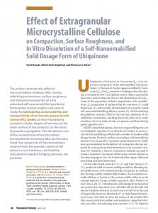
MATERIALS INVESTIGATED The mixtures that were the focus of attention in the present investigation involved two standard Irish asphalt mixtures, namely, a 30% 14-mm hot-rolled asphalt (HRA) mixture [BS 594: Part 1 (BSI 1992)] and a 20-mm dense base course macadam (DBC) mixture [BS 4987: Part 1 (BSI 1993a)]. The composition of the two mixtures, summarized in Table 1, represents two different grading profiles, namely, an open graded sandy mix (HRA) and a continuous grading mix (DBC), as shown in Fig. 1. These were expected to respond differently to various compaction methods. For both mixtures binder contents toward the lower end of the design spectrum were purposely chosen to obtain fatigue prone mixtures. This, however, led to difficulties in compacting the mixtures, which resulted in the void contents achieved being relatively high. SPECIMEN PREPARATION Raw materials were sampled, conditioned, and mixed as described elsewhere by Hartman (2000). Depending on the compaction method that was used and the size of the batch, either the mixed materials were immediately transferred into the compaction mold and compacted or they were stored at the mixing temperature and compacted in smaller batches. Six different laboratory compaction methods were investigated initially: • Roller compaction (R1 and R2): Two sets of each mixture at different void contents • Gyratory compaction (G)
FIG. 1. tion
Aggregate Grading of Bituminous Mixtures under Investiga-
Mix Constituents
a
HRA (% by Weight Passing Sieve)b
DBC (% by Weight Passing Sieve) 20 mm 98
14 mm
10 mm
6.3 mm
3.35 mm
300 m
75 m
20 mm
14 mm
10 mm
2.36 mm
212 m
75 m
82
66
52
40
16
4.5
100
97
80
66
30
10
a
Bitumen content: 4.2% (100 Pen); target void content: 6% (by volume). b Bitumen content: 7.3% (50 Pen); target void content: 4% (by volume). JOURNAL OF TRANSPORTATION ENGINEERING / SEPTEMBER/OCTOBER 2001 / 371
• • • •
Marshall compaction (M) Vibrating hammer compaction (V) Static compression (C) Site compaction (S) only for the DBC mixture using a lightweight (half-ton) vibrating steel drum pedestrian roller
Roller Compaction The standard Cooper Research Technology Roller Compactor (Ripley, U.K.) was used to compact the loose material with a segment of a roller that is said to allow the aggregate particles to move relative to one another and orientate themselves in a manner similar to in situ material. The precise depth of the slab can be preset, enabling a target density to be achieved. The slabs that were produced measured 305 ⫻ 305 ⫻ 50 mm and required roughly 11 kg of mix. Four or five specimens were cored from each compacted slab and 5 mm were machined from the flat ends to obtain the required specimen dimensions for ITFT. With the first batch of samples (R1), difficulties were encountered in achieving the target mixture densities. For both mixtures, fine construction cracks and bands of voids in a direction transverse to the compaction direction were visible on the top and bottom surfaces of the slabs. Generally, it seemed that the HRA mixture produced voids of a smaller volume and that larger voids were associated with areas within a specimen where large aggregates were grouped. The first batch of the DBC mixture was compacted at slightly lower temperatures, and a higher number of roller passes resulted in the slabs being overcompacted. A second set of roller specimens (R2) was compacted in an effort to produce more uniform samples with a density closer to the target. Apart from a slightly higher compaction temperature, a different compaction procedure was used for the HRA R2 set. Instead of setting the target compaction depth to the final slab depth at the beginning of the compaction process, the depth setting was incrementally reduced, resulting in a smoother surface finish and a more even distribution of voids. Gyratory Compaction A servocontrolled gyratory compactor, which applies a simultaneous static compression and shearing force because of the rotation of the top surface of the mold, was used to compact the mixtures. The static compaction pressure was set at 700 kPa, with an angular velocity of 30 gyrations/min, and the gyratory angle was set at 1.25⬚. Because of minimum height restrictions on specimens compacted in 100-mm-diameter molds (66 mm, prEN 12697-31) [European Committee for Standardisation (ECS) 1997], specimens were compacted to a height of 100 mm. Two ITFT specimens were cut from each compacted specimen and the flat ends were machined to obtain final samples (40-mm thickness). The average number of gyrations required to compact both HRA and DBC specimens was approximately 60 gyrations. An inspection of the machined flat ends showed a generally uniform distribution of voids for the HRA specimens but a clustering of voids close to the circumference of the DBC samples. Marshall Compaction A compaction trial was conducted to determine the compaction effort required to achieve the target void content for both the HRA and the DBC mixtures. For each mixture, the number of hammer blows and the specimen thickness were varied and the achieved void content was determined from the specimen dimensions. Consequently it was decided to compact a 50-mm-thick sample by applying 50 hammer blows on each
flat end. The compacted specimens were then precision trimmed to 40-mm thickness for fatigue testing. The placing of the loose mix in the mold and the amount of tamping before compaction heavily influenced the surface finish of the specimens. Large voids were visible on the curved molded sides of the samples. Inspection of the machined ends identified a number of aggregates that had been fractured by the impact compaction force. Vibrating Hammer Compaction A standard Kango handheld hammer, which is usually used to determine refusal densities [BS 598 (BSI 1989)], was used to compact the specimens. The hammer has a power consumption of 750 W and operates at a frequency of 25 Hz. Although the amount of compaction energy that is applied to the sample is highly operator dependent and difficult to control, it was believed that this method represents a markedly different way of reducing voids in the mixture and for this reason was included in the study. Again, a compaction trial was done to determine the required compaction effort, or vibrating time. For both mixtures, a vibrating time of 90 s (⫾5 s) on each side of a 50-mm-thick sample was used. A downward force of approximately 500 N was applied to the sample. After compaction, the flat sides of the samples were machined to obtain a 40-mm-thick specimen for fatigue testing. The placing of and tamping with the loose mix also seemed to influence the surface finish of the specimens. Compared to the Marshall specimens, fewer voids were visible on the molded curved sides. Inspection of the machined flat ends showed a very uniform distribution of voids for the HRA specimen, whereas the voids were localized in patches for some of the DBC specimens. Static Compression Compaction The static compression compaction technique involved the compression of a sample of loose mix in a standard Marshall mold under a compression force applied by a hydraulic actuator. Applying the load at either a uniform strain rate or loading rate controls the rate of compaction. A number of loading procedures was investigated in an effort to obtain the target densities but without evident success. The maximum load capability of the equipment was 200 kN, but severe crushing of the aggregates (especially with the DBC mix) occurred at lower loads (150 kN). Because of this method’s inability to compact specimens to the required density, it was abandoned and pursued no further. Site Compaction Site compacted specimens were machined from an experimental section of road pavement used in an in situ accelerated loading experiment (Hartman 2000; Hartman et al. 2001; Owende et al. 2001). The basic construction of this experimental track involved overlaying an existing road section with a 50-mm DBC layer and incorporating appropriate instrumentation in order that degradation of the layer could be monitored. The total size of the overlaid area was approximately 120 m2, which required about 15 ton of mix. During plant mixing, it was intended to achieve the same grading and bitumen content that had been used during the laboratory investigation. Because of accessibility constraints to the site, the material was hand laid and compacted with a 0.5-ton pedestrian roller. Curing, Machining, and Storage of Specimens Programs of fatigue testing usually span over some weeks and thus necessitate storage of specimens until testing. During
372 / JOURNAL OF TRANSPORTATION ENGINEERING / SEPTEMBER/OCTOBER 2001
this study, laboratory equipment situated in different laboratories was used to produce and test specimens. This required that specimens be produced in large batches and then tested as and when equipment became available. The size of the available ovens and time constraints on their use made shortand long-term SHRP aging impractical. To ensure that the time between testing did not influence the fatigue properties of the specimens, a curing method suggested by Aglan and Figueroa (1993) was used. This involved curing the compacted specimens at 60⬚C in a forced draft oven for 24 h. To ensure that the specimens did not lose their shape during the curing process, they were cured while still inside the compaction molds. Site and roller compacted specimens were cored from the roadside and slab specimens, using a diamond-coated asphalt coring bit (100-mm inner diameter). To eliminate any anomalies associated with some specimens having machined ends (e.g., gyratory) and others not (e.g., Marshall), the flat ends of all cylindrical specimens were machined. The machined ends of the specimens were then polished on a large wheel sander to remove any blade marks and slight skewness. Before machining and polishing, specimens were stored at 5⬚C. This ensured that the specimens did not lose their shape under the clamping and prevented bitumen flow caused by heating under the polishing pad. Finally the flat ends were spray painted using a white emulsion paint to increase the visibility of the final crack pattern. Machined and painted specimens were again stored at 5⬚C and tested within 50 days. RESULTS AND DISCUSSION Measurement of Void Content Void contents, as determined using the parafilm measurement method (SHRP M-008 1994), for specimens used in the ITFT comparisons are listed in Table 2. The mean value mx of the multiple measurements is given as the best estimate of the void content for the particular specimen batch. The standard deviation sx indicates the scatter of the measurements and therefore quantifies the inherent void content variability. AlTABLE 2.
Summary of Parafilm Void Content Measurements VOID CONTENT (%)
Compaction method R1 R2 M V G S Repeatability (Read 1996) Set 1 Set 2
HRA
DBC
mx
sx
vx
mx
sx
vx
5.0 4.8 5.3 4.0 3.5 —
1.2 0.3 0.5 0.6 0.4 —
0.24 0.07 0.10 0.16 0.12 —
3.8 5.8 6.2 5.4 4.4 11.5
0.3 0.5 0.5 1.0 0.4 0.8
0.09 0.08 0.08 0.18 0.08 0.07
3.2 4.7
0.2 1.3
0.05 0.28
5.0 5.5
0.5 0.3
0.08 0.05
ternatively, the standard deviation may be substituted by its percent ratio to the mean value, which is indicated as the coefficient of variation vx. It was very difficult to control the void content when using the different compaction methods. This was especially true for the Marshall (M) and vibratory (V) compacted specimens. Although trial runs were conducted to determine the vibrating time (vibratory) and number of blows (Marshall), variations of void content still occurred. Machining the flat ends of the cores also complicated the targeting of a specific void content, as a higher density of voids is invariably found on the surfaces. As mentioned previously, the R2 specimens represent a second set of roller compacted specimens, where a void content closer to the target (6% for DBC and 4% for HRA) was achieved. For the site specimens, the long hauling time from Dublin (about 5 h), manual nature of the laying operation, and air temperature ( 10%). The repeatability data, also listed in Table 2, were taken from Read (1996) and formed part of a large data set, which included numerous mixtures and was used to validate the present ITFT. The specimens were compacted using the roller method and showed excellent fatigue repeatability despite the relatively large differences in void content. Considering the variations in void content of Read’s repeatability data for Sets 1 and 2, the void contents of the present R2, M, V, and G specimens are reasonably consistent; consequently, the differences in fatigue response can be attributed to the method of compaction rather than to any difference in void content. Statistical t-tests were performed on the data to determine whether any of the void content data sets were identical. Calculated t-distributions are summarized in Table 3. Data sets that conformed to the 95% confidence limit (⫺2.101 ⱕ t ⱕ 2.101) are highlighted in the table. For the HRA specimens R1-R2 and R1-M batches tested identical whereas the R2-M, R1-V, and V-G batches fell just outside the 95% confidence limit. For the DBC specimens, on the other hand, the R2-M and R2-V data sets fell within the 95% confidence limit whereas the M-V batch was almost within the limit. ITSM Measurements The results of the ITSM measurements, carried out at a target horizontal deformation of 5 m and the standard 20⬚C test temperature, are summarized in Fig. 2. For both mixtures, the roller compacted specimens exhibited lower ITSM values whereas the Marshall specimens had higher ITSM values, which was in agreement with the findings of Ulmgren (1996). Ulmgren also reported lower stiffness values for site compacted specimens, although the low value mea-
TABLE 3. Void Content t-Test for HRA and DBC Specimens Compacted Using Roller (R1 and R2), Marshall (M), Vibratory (V), Gyratory (G), and Site (S) Compaction Methods (Highlighted Results Indicate Data Sets That Conform to 95% Confidence Limit)
JOURNAL OF TRANSPORTATION ENGINEERING / SEPTEMBER/OCTOBER 2001 / 373
FIG. 2.
TABLE 4.
Summary of ITSM Measurements (Scatter Bars Show Variations within Each Specimen Batch)
ITSM t-Test for HRA and DBC Specimens (Highlighted Results Indicate Data Sets That Conform to 95% Confidence Limit)
FIG. 3.
ITFT Measurements for HRA Specimens
sured in this instance can also be attributed to the significantly lower void content. Again, statistical t-tests were performed on the data to determine whether any of the data sets were identical. Calculated t-distributions are summarized in Table 4. Data sets that conformed to the 95% confidence limit (⫺2.101 ⱕ t ⱕ 2.101) are highlighted in the table. For both mixtures, only two data sets were statistically identical, namely, the R1-R2 and V-G groups for the HRA mixture and the R2-S and M-V groups for the DBC mixture. Relating these comparisons to the void content tests, it was found that in only one instance (i.e., the two roller compacted HRA sets R1-R2) did the void content and ITSM comparison agree.
ITFT Measurements Figs. 3 and 4 and Table 5 summarize the results from the ITFT in the form of initial tensile strain plotted against the number of load cycles to failure. All the regressed fatigue lines for HRA appear very close to each other. This is also true, but to a lesser extent, for the DBC mixture apart from the Marshall compacted specimens, which show significantly lower fatigue strengths. An empirical relationship of the following form was used during the regression analysis:
374 / JOURNAL OF TRANSPORTATION ENGINEERING / SEPTEMBER/OCTOBER 2001
N = k1(εT)k2
(1)
FIG. 4.
ITFT Measurements for DBC Specimens
TABLE 5.
Calculated Regression Coefficients for ITFT DBC
HRA Coefficients k1
k2
R2
Cycles at 100 strain
⫻ 109 ⫻ 109 ⫻ 1010 ⫻ 1014 ⫻ 1012 — 1.7 ⫻ 1012
⫺2.407 ⫺2.465 ⫺2.686 ⫺4.456 ⫺3.775 — ⫺3.226
0.89 0.96 0.92 0.83 0.97 — —
48,738 75,160 79,903 777,290 258,736 — 606,789
Compaction method R1 R2 M V G S Read (1996) roller
TABLE 6.
3.2 6.4 1.9 6.4 9.2
Coefficients k1 2.7 3.2 1.2 7.0 1.5 3.3 2.3
⫻ ⫻ ⫻ ⫻ ⫻ ⫻ ⫻
1011 109 107 1011 1012 109 1011
k2
R2
Cycles at 100 strain
⫺3.220 ⫺2.546 ⫺1.619 ⫺3.534 ⫺3.694 ⫺2.355 ⫺3.154
0.99 0.92 0.95 0.93 0.88 0.95 —
96,596 26,269 6,857 59,936 62,883 64,595 113,107
Determined F-Values for HRA and DBC Specimens (Highlighted Results Indicate Data Sets That Conform to 95% Confidence Limit)
where N = number of strain cycles to failure; εT = initial tensile strain (strain); and k1 and k2 = material coefficients, listed in Table 5. The regressed fatigue lines were statistically compared and the determined F-distributions are listed in Table 6. Data sets that conformed to the 95% confidence limit (F < 3.59) are highlighted in the table. The generally lower F-distribution values determined for HRA would suggest a closer agreement between the fatigue response of HRA specimens prepared with different compaction methods. The HRA, being a gap-graded mixture, relies less on aggregate interlock for its strength than the continuously graded DBC mix. To achieve interlock, the aggregates require reorientation during compaction, which would be more effectively achieved by compaction methods having a kneading/rolling action. The poor performance of the DBC Marshall specimen agrees with this theory. Comparing statistically identical sets determined for void content measurements (Table 3
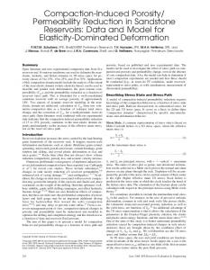
with Table 6), it is noticed that two HRA sets (R1-R2 and R1M) and the R2-V DBC set also show identical fatigue behavior. Fatigue Failure Characteristics All the different failure patterns observed by Hudson and Kennedy (1968) were identified during the present investigation. Examples of the most commonly observed failure patterns are shown in Fig. 5. All the R1 specimens failed because of excessive deformation. The occurrence of construction defects had a marked influence on the failure features. As shown in Fig. 6, these defects tended to divert the fracture plane away from the vertical. Compared to the HRA mixture, DBC specimens showed a wider area of damage between the loading platens, and this is thought to be a result of its continuous interlocking grading. Ninety percent of the R2 specimens failed because of ex-
JOURNAL OF TRANSPORTATION ENGINEERING / SEPTEMBER/OCTOBER 2001 / 375
FIG. 5. Examples of Fatigue Failure Patterns on ITFT Specimens; in All Cases Loading Axis Was Top to Bottom: (a) Ideal Failure (HRA-M); (b) Single Cleft (HRA-V); (c) Double Cleft (HRA-M); (d) Double Split (DBC-R1); (e) Multiple Cleft (DBC-R1); (f) Localized Crushing Failure (DBC-S); (g) Combined Failure, Multiple Cleft/Crushing (HRA-R1); (h) Combined Failure, Multiple Cleft/Crushing (HRA-R1); (i) Total Deformation Failure (DBC-S)
FIG. 6. Specimens (100-mm-Diameter) Showing Deviation of Failure Plane from Vertical due to Presence of Construction Defects; Construction Defects Occurred Parallel to Horizontal Axis
cessive permanent deformation. In the case of DBC specimens, the presence of large aggregates seemed to localize the damage more than in the HRA specimens, where small cracks are distributed within the mortar. An examination of the fracture surfaces of DBC roller compacted samples showed a very irregular surface, indicating that a relatively large amount of plastic deformation had taken place during fracture. The fracture surface also shows a number of large aggregate surfaces, which would suggest that the fracture plane diverted to grow along aggregate surfaces that were lying parallel to the vertical tensile plane. The DBC-S samples failed predominantly (80%) because of permanent deformation, except for the high stress level specimens. A wide band of network cracks between the loading platens made it difficult to distinguish a specific failure pattern for a number of specimens [Fig. 5(i)].
All of the DBC-G and approximately 66% of the HRA-G samples failed with a violent fracture. The main failure patterns observed were single clefts and localized crushing at the loading platens. For some specimens (DBC-G), the fracture plane showed uncoated aggregates, which would indicate poor mixing. All Marshall and vibratory specimens failed with violent fracture. Mostly single and double clefts were observed. Generally, a straighter fracture plain and narrower damage area were observed, particularly for the M samples. Grinding marks were observed on the fracture planes of DBC-V specimens. This may have been due to high vibrating loads during compaction, which would force aggregates in contact without them being able to orientate in alignment with the force. CONCLUSIONS Table 7 ranks the different compaction methods according to their fatigue performance (life at 100 strain), stiffness (5m target deformation), and void content (measured with parTABLE 7. Properties
Ranking of Compaction Methods According to Mixture HRA
Voids
DBC
Stiffness
Fatigue
Voids
Stiffness
Fatigue
M G V R1 R2 —
V G M R2 R1 —
R1 G V R2 M S
G M V R1 R2 S
R1 S G V R2 M
G V R2 R1 M —
376 / JOURNAL OF TRANSPORTATION ENGINEERING / SEPTEMBER/OCTOBER 2001
afilm). Specifically it has been found that roller compacted specimens had lower stiffness properties that were similar to site compacted specimens. Higher stiffnesses were measured for Marshall and gyratory compacted specimens. Although it is generally agreed that site compaction is more effective, the fatigue performance of the DBC site compacted specimens was surprisingly good. Regardless of their high void content (nearly twice as high as the laboratory compacted specimens), their fatigue strength was ranked second. Shortterm aging of the mixture might have had a greater influence than anticipated in this regard. Apart from the site compacted specimen results, the void content and fatigue ranking seem to agree. In nearly all instances, the vibratory and gyratory samples are ranked in sequence. The kneading action generated by the site, laboratory roller, and gyratory compactors under a relatively low vertical load causes high shear stresses that enable the attainment of a uniform distribution and displacement of mixture ingredients and reorientation of aggregates. It is mostly excessive permanent deformation failure that was observed to occur in these specimens. Other forms of laboratory compaction, such as the Marshall hammer, only generate a direct load that results in limited deformation and a less uniform distribution of mixture ingredients. This leads to squeezing of the binder film on the aggregate surfaces and a more violent fatigue fracture. Continuously graded mixtures rely heavily on their aggregate structure for their strength; thus, during the compaction process, the formation of an effective aggregate structure is crucial. A kneading compaction action accommodates the reorientation and formation of aggregate interlock and thus plays a more predominant role in the compaction of these mixtures as opposed to gap-graded mixtures with a large percentage of finer graded material, where the mere reduction of voids can be achieved through direct compression. The findings of this study of two standard Irish bituminous mixtures (HRA and DBC) would suggest that similar indirect tensile fatigue strengths would be measured in practice for gap-graded mixtures, when using either the Marshall or the roller compaction methods. For continuously graded mixtures, the Marshall compaction technique would probably produce specimens with significantly inferior indirect tensile fatigue strengths. However, any significant variations from the constituents of these two particular mixtures, such as the aggregate size, void, and binder content, would not necessarily provide a similar behavior. ACKNOWLEDGMENTS The writers would like to express their gratitude to Dr. Ian Jamieson and Frank Clancy of the National Roads Authority, Dublin, Ireland, Michael Byrne of Roadstone Dublin Ltd., Dublin, Ireland, and Enterprise Ireland, Dublin, Ireland (Applied Research Grants HE/1996/148 and HE/ 1998/288) for supporting this research. The assistance provided by Amanda Gibney, Michael MacNicholas and Tom Webster of the Civil Engineering Department at the National University of Ireland, Dublin, is gratefully acknowledged.
REFERENCES Aglan, H. A., and Figueroa, J. L. (1993). ‘‘Damage-evolution approach to fatigue cracking in pavements.’’ J. Engrg. Mech., ASCE, 119(6), 1243–1259. Bonnot, J. (1997). ‘‘Selection and use of the procedures for laboratory compaction of bituminous mixtures.’’ Performance related test procedures for bituminous mixtures, M. D. Gilchrist and A. M. Hartman, eds., Boole Press, Dublin, Ireland, 52–73. British Standards Institution (BSI). (1989). ‘‘Sampling and examination of bituminous mixtures for roads and other paved areas; Part 104. Methods of test for the determination of density and compaction.’’ BS 598: Part 104, London. British Standards Institution (BSI). (1992). ‘‘Hot rolled asphalt for roads and other paved areas.’’ BS 594: Part 1, London.
British Standards Institution (BSI). (1993a). ‘‘Coated macadams for roads and other paved areas.’’ BS 4987: Part 1, London. British Standards Institution (BSI). (1993b). ‘‘Method for the determination of the indirect tensile stiffness modulus of bituminous mixtures.’’ BS DD 213, BSI Draft for Development, London. British Standards Institution (BSI). (1996). ‘‘Method for the determination of the fatigue characteristics of bituminous mixtures using indirect tensile fatigue.’’ BS DD ADF, BSI Draft for Development, London. Button, J. W., Little, D. N., Jagadam, V., and Pendleton, O. J. (1994). ‘‘Correlation of selected laboratory compaction methods with field compaction.’’ Transp. Res. Rec. 1454, Transportation Research Board, Washington, D.C., 193–201. Dunaiski, P. E., and Hugo, F. (1990). ‘‘A proposed method for measuring the lateral displacement during indirect tensile tests on asphalt briquettes using linear variable differential transducers.’’ Proc., Int. RILEM Symp., Mech. Tests for Bituminous Mixtures, Paper 13, H. W. Fritz and E. Eustacchio, eds., RILEM, Cachan Cedex, France. Epps, J. A., Gallaway, B. M., Harper, W. J., Scott, W. W., and Sealy, J. W. (1969). ‘‘Compaction of asphalt concrete pavements.’’ Res. Rep. 90-2F, Texas Transp. Inst., Texas Highway Department, Austin, Tex. Eriksen, K. (1993). ‘‘Microscopical analysis of asphalt-aggregate mixtures related to pavement performance.’’ Note 245, Danish Rd. Inst., Ministry of Transport, Roskilde, Denmark. European Committee for Standardisation (ECS). (1997). ‘‘Test methods for hot mix asphalt—Specimen preparation gyratory compactor.’’ prEN 12697-31, Draft European Standard, Brussels. Fairhurst, C. E., Kosla, N. P., and Kim, Y. R. (1990). ‘‘Resilient modulus testing of asphalt specimens in accordance with ASTM D 4123-82.’’ Proc., Int. RILEM Symp., Paper 28, H. W. Fritz and E. Eustacchio, eds., RILEM, Cachan Cedex, France. Fordyce, D. (1997). ‘‘The compaction of asphaltic mixtures.’’ Performance related test procedures for bituminous mixtures, M. D. Gilchrist and A. M. Hartman, eds., Boole Press, Dublin, Ireland, 74–87. Hartman, A. M. (2000). ‘‘Experimental investigation into the mechanical performance and structural integrity of bituminous road pavement mixtures under the action of fatigue load conditions.’’ PhD thesis, National University of Ireland, Dublin, Ireland. Hartman, A. M., Owende, P., Gilchrist, M. D., Ward, S., and Clancy, F. (2001). ‘‘In-situ accelerated testing of bituminous mixtures.’’ J. Rd. Mat. and Pavement Des. (in press). Harvey, J., Eriksen, K., Sousa, S., and Monismith, C. L. (1994). ‘‘Effects of laboratory specimen preparation on aggregate-asphalt structure, airvoid content measurement, and repetitive simple shear test results.’’ Transp. Res. Rec. 1454, Transportation Research Board, Washington, D.C., 113–122. Harvey, J., and Monismith, C. L. (1993). ‘‘Effects of laboratory asphalt concrete specimen preparation variables on fatigue and permanent deformation test results using Strategic Highway Research Program A003A proposed testing equipment.’’ Transp. Res. Rec. 1417, Transportation Research Board, Washington, D.C., 38–48. Hudson, W. R., and Kennedy, T. W. (1968). ‘‘An indirect tensile test for stabilized materials.’’ Res. Rep. 9801, Center of Highway Research, University of Texas, Austin, Tex. Huschek, S. (1985). ‘‘The deformation behaviour of asphaltic concrete under triaxial compression.’’ Proc., AAPT, 54, 407–431. Mohammad, L. N., and Paul, H. R. (1992). ‘‘Evaluation of a new indirect tension test apparatus.’’ Transp. Res. Rec. 1353, Transportation Research Board, Washington, D.C., 62–68. Nunn, M. E. (1978). ‘‘Deformation testing of dense coated macadam: Effect of method of compaction.’’ Rep. 870, Transportation and Road Research Laboratory, Crowthorne, U.K. Nunn, M. E., and Smith, T. M. (1996). ‘‘The indirect tensile stiffness modulus test: Assessment of suitability of an asphalt performance test.’’ TRL Proj. Rep. CE/140/96, Crowthorne, U.K. Owende, P., Hartman, A. M., Ward, S. M., Gilchrist, M. D., and O’Mahony, M. J. (2001). ‘‘Minimizing distress on flexible pavements using variable tire pressure.’’ J. Transp. Engrg., ASCE, 127(3), 254– 262. Read, J. M. (1996). ‘‘Fatigue cracking of bituminous paving mixtures.’’ PhD thesis, University of Nottingham, Nottingham, U.K. Roque, R., and Buttlar, W. G. (1992). ‘‘The development of a measurement and analysis system to accurately determine asphalt concrete properties using indirect tensile mode.’’ Proc., AAPT, 61, 304–332. Ruth, B. E., and Maxfield, J. D. (1977). ‘‘Fatigue of asphalt concrete.’’ Dept. of Civ. Engrg. Final Rep. 245-D54, University of Florida, Gainesville, Fla. Said, S. F. (1998). ‘‘Validation of indirect tensile test for fatigue testing of bituminous mixes.’’ Proj. 60209, Swedish National Road and Transport Research Institute, Linkoping, Sweden. Santagata, E., and Bassani, M. (1999). ‘‘Improved use of the repeated
JOURNAL OF TRANSPORTATION ENGINEERING / SEPTEMBER/OCTOBER 2001 / 377
load indirect tensile test.’’ Proc., 3rd Eur. Symp. on the Perf. and Durability of Bituminous Mat. and Hydr. Stabilised Compos., J. G. Cabrera and S. E. Zoorob, eds., Aedificatio Publishers, Freiburg, Germany, 493–516. Sousa, J. B., Harvey, J., Painter, L., Deacon, J. A., and Monismith, C. L. (1991). ‘‘Evaluation of laboratory procedures for compacting asphaltaggregate mixtures.’’ Rep. SHRP-A/UWP-91-523, Institute of Transportation Studies, University of California, Berkeley, Calif. Sousa, J., Tayebali, J., Harvey, P., Hendricks, P., and Monismith, C. L. (1993). ‘‘Sensitivity of Strategic Highway Research Program A-003A testing equipment to mix design parameters for permanent deformation and fatigue.’’ Transp. Res. Rec. 1384, Transportation Research Board, Washington, D.C., 69–79. Strategic Highway Research Program (SHRP). (1994). ‘‘Fatigue response of asphalt aggregate mixes.’’ SHRP-A-404, National Research Council, Washington, D.C. Strategic Highway Research Program (SHRP M-008). (1994). ‘‘Standard
test method for determining the fatigue life of compacted bituminous mixtures subjected to repeated flexural bending.’’ The superpave mix design system: Manual of specifications, test methods, and practices, SHRP-A-379, National Research Council, Washington, D.C. Ulmgren, M. (1996). ‘‘Functional testing of asphalt mixes for permanent deformation by dynamic creep test; modification of method and round robin test.’’ Euroasphalt and Eurobitume Congress CD-ROM, European Asphalt Pavement Association, Strasbourg, Germany. Vallerga, B. A. (1951). ‘‘Recent laboratory compaction studies of bituminous paving mixtures.’’ Proc., AAPT, 20, 117–153. Von Quintus, H. L., Scherocman, J. A., Hughes, C. W., and Kennedy, T. W. (1988). ‘‘Development of asphalt-aggregate mixture analysis system: AAMAS.’’ Rep. 338, Nat. Res. Council, Transportation Research Board, Washington, D.C. Voskuilen, J. L. M. (1996). ‘‘Influence of compaction methods on the density distribution of asphalt concrete specimens.’’ Proc., Int. Workshop on Use of Gyratory Shear Compactor, LCPC, Nantes, France.
378 / JOURNAL OF TRANSPORTATION ENGINEERING / SEPTEMBER/OCTOBER 2001