Effect of Phase Advance on the Brushless DC Motor Torque Speed Respond M. Syafiq Mohd1, M.N.Karsiti1 and M. Syaifuddin Mohd2,3 *
Email:
[email protected] Phone: +60136465737 1 Electrical and Electronics Engineering Department 2 Mechanical Engineering Department 3 MOR Energy Universiti Teknologi PETRONAS, 32610 Bandar Seri Iskandar, Perak, Malaysia
Abstract. Brushless direct current (BLDC) motor is widely used in small and medium sized electric vehicles as it exhibit highest specific power and thermal efficiency as compared to the induction motor. Permanent magnets BLDC rotor create a constant magnetic flux, which limit the motor top speed. As the back electromotive force (EMF) voltage increases proportionally with motor rotational speed and it approaches the amplitude of the input voltage, the phase current amplitude will reach zero. By advancing the phase current, it is possible to extend the maximum speed of the BLDC motor beyond the rated top speed. This will allow smaller BLDC motor to be used in small electric vehicles (EV) and in larger applications will allow the use of BLDC motor without the use of multispeed transmission unit for high speed operation. However, increasing the speed of BLDC will affect the torque speed response. The torque output will decrease as speed increases. Adjusting the phase angle will affect the speed of the motor as each coil is energized earlier than the corresponding rise in the back EMF of the coil. This paper discusses the phase advance strategy of Brushless DC motor by phase angle manipulation approaches using external hall sensors. Tests have been performed at different phase advance angles in advance and retard positions for different voltage levels applied. The objective is to create the external hall sensor system to commutate the BLDC motor, to establish the phase advance of the BLDC by varying the phase angle through external hall sensor manipulation, observe the respond of the motor while applying the phase advance by hall sensor adjustment.
1. INTRODUCTION In the recent years increase in energy prices as well as global climate changes have increase public awareness and government effort to seek alternative technology for clean energy transportation [1]. There is also a rapid increase in the adoption of a single seat or two-seat lightweight commuter electric vehicle [2]. Figure 1 shows small commuter electric vehicles, EV, in the form of an electric scooter and a prototype single seat electric vehicle. In the segment of small to medium sized hybrid electric and electric vehicles, majority of electric motor utilized is typically of the BLDC motor type controlled by a three phase motor controller [3]. The use of high strength rare earth permanent magnets allows the BLDC motor to exhibit higher specific power and thermal efficiency as compared with induction motor. However, this constant magnetic field strength limits the maximum operational speed of the motor as the motor cannot produce useful torque when the amplitude of back electromotive force, EMF reaches the amplitude of input voltage of the coils [4]. In this study, single seat electric vehicle will be used in the field test to verify the phase advance control algorithm.
Figure 1: Small commuter electric vehicles – Vectrix E Scooter and UTP prototype single seat EV. Study shows that it is possible to increase the operating speed of the motor by advancing the phase current with reference to back EMF [5-9]. According to H. Kong et al., transformers EMF in the voltage equation can restrain the increase of the peak back EMF when phase current lead the phase voltage back EMF [7]. There are several research related the phase advance. HC. Kim and JM. Kim was used in-phase concept which phase current compensates lagging angle based on back EMF because of increasing reactance at high speed. Conventional phase advance control method was optimized by compensating the difference of lagging angle between phase current and back EMF. S.M. Sue et al. in their paper stated that inverter gating time has been advanced so that phase angle of the stator current can lead the corresponding back EMF and by that the reluctance torque can be developed properly [11]. Cambier et al. claim improvements in phase timing advancement to maintain constant power output during high speed use. Phase advance angle manipulation is one of the methods in applying the phase advance. From literature, there are several approaches that been used to utilize phase angle manipulation. Manipulation of the external hall sensor systems has been used as the approach in applying the phase advance through varying the phase angle. Some preliminary works on motor characterization and modeling has been done. Experiment was established by testing the motor in varying phase advance angle. Different input voltage levels also been applied in the test. Output speed and the output torque of the motor have been observed. Most of the effects, benefits and drawbacks of the phase advanced control algorithm are not widely discussed in most literatures during partial and transitional loads expected such as in the operation of an electric vehicle. In actual vehicle operation, the drive cycle characteristics of the vehicle will determine the actual required operating points of the motor and majority of these points are located below the peak torque curve and are transitional in nature [10].
PROBLEM FORMULATION Installing multispeed transmission unit in order to allow the electric drivetrain to be able to deliver high torque at low speed and at the same time are able to operate at a high cruising speed [11] will has additional driveline loss of around 10 percent [12]. The BLDC motor is capable of energy conversion at a peak rate of over 90 percent [13]. The top operational speed of this type of motor is largely limited by the constant magnetic field presence due to the existence of permanent magnets in the rotor. The torque speed respond will effect as the phase advance is applied. As the speed increase, the torque value will be decreased.
EFFECT OF APPLYING THE PHASE ADVANCE TO A BLDC A.
Hypothesis 2
There are several effects of applying the phase advance to a BLDC: 1. The top speed of BLDC can be increased by advancing the phase current. 2. The peak torque will be reduced below the base speed when advancing the phase current. 3. The optimum angle for phase advance operation has to be optimized as a function of motor speed and motor load. Figure 2 shows the proposed hypothesis of the correlation between motor peak torque, motor speed and phase advance angle. The motor peak torque at zero phase advance angle is a slice of the curve intersecting the xz-plane (torque-phase advanced angle).
Figure 2: Torque vs Speed for different phase advance angles PRELIMINARY WORK Axial Flux Motor Characterization And Modelling A custom made 200 W axial flux BLDC motor was used for the test. A MATLAB model from the existing model in the MATLAB has been used and modified as shown in Figure 4. Equations (1) and (2) describe the relevant equations for back EMF per unit speed and electrical torque for axial flux BLDC motor. All the measured and assumed values are entered into a MATLAB script, which is used to calculate the back EMF rms amplitude and to calculate the motor electrical torque constant. Axial flux BLDC motor equations: [14] Back EMF per unit speed: Ef = π
fN1kw1фf = π
p kw1фf ns=kEns
(1)
Where: f = frequency N1 = no of turns фf = magnetic flux density kw1 = winding factor p = no of pole pair kE = EMF constant ns = motor speed Torquerms , Td: Td =
pN1 kw1фfIa=kTIa
where: 3
(2)
m1= no of phase kT= torque constant Ia= Iphaserms Using these equations, a MATLAB script is generated to calculate the motor properties as shown in Figure 3. The user will have to select motor topologies of either radial flux BLDC or axial flux BLDC and also the physical dimensions and other motor design properties. The resultant torque constant, coil resistance, coil induction and back EMF constant are then used by a dynamic model in the motor drive simulation.
Figure 3: MATLAB script to calculate back EMF and torque constant for the BLDC motor Simulation
Figure 4: MATLAB Simulink model of the BLDC motor A MATLAB Simulink model is then created using Power System block sets to simulate the permanent magnet BLDC motor as in Figure 5. The simulation model incorporate phase current control, a constant voltage power supply and the analytical model of the motor as determined by equations (1) and (2) for radial flux BLDC motor or equations (3) and (4) for axial flux BLDC motor. The main goal of the preliminary simulation work is to create a model for the permanent BLDC motor, which then can be validated using the actual test data. The 4
validated model can then be used to study the effect of phase advanced control algorithms. Simulation Results The preliminary result obtained before from the simulation is shown in Figures 5 and 6. The torque constant and back EMF constant is similar to actual torque constant, Kt provided by the manufacturer. The model is not entirely accurate, since there is a lack of information about the magnetic strength of the magnets and the actual number of turns of the coils, similar output characteristics between the model and the actual motor specifications allows for useful comparison between the model operation and actual motor operation.
Figure 5: Motor torque output from simulation
Figure 6: Phase current waveforms from simulation Based on the simulation results, the model can be used to study the effects of phase advanced control on the motor torque output. However, an accurate comparison between the simulated model and the actual motor requires the installation of a rotary torque meter and an adjustable load to control the operating points (torque and speed) of the BLDC motor. Experiments have been conducted using Kelly BLDC and Electrocraft BLDC controllers. A programmable Sorensen Power supply provides a constant voltage supply to the motor controller. The test has been done in no- load test condition. Figure 8 show the details of the external hall sensor set-up. The main reason of using the external adjustable hall sensors is to physically vary the phase advanced angle. At present, this is the only viable solution as the programming code of the motor controller is not accessible. In the future, it is possible to control a motor drive unit using custom made programmable logic board to replace the motor controller altogether for full control of the phase advance angle. Moreover, the implementation of the phase advanced control might require 5
additional set of hall sensors located perhaps at certain angle from the default set of hall sensors. External Hall Sensor The test has been done using a custom made axial flux BLDC motor that fabricated by other researcher. A set of hall sensor used to commutate that motor. The holder of that hall sensor is designed so that the position can be changed to different phase angle. Figure 7 shows the hall sensors holder used for the motor.
Figure 7: Hall sensor positioning The test has been done by using test bench that run by custom made axial flux motor as shown in Figure 8.The test has been established with no load and load applied.
Figure 8: custom made axial flux motor test bench [15]
RESULTS AND DISCUSSION An axial flux BLDC motor has been tested using Kelly BLDC controller. The test has been done in no load condition for different phase advance angle and different voltage applied. The objective is to observe the effect of varying phase advance angle at different voltage applied. The angle test is at advance angle and also at retard angle. Table 1 shows the axial flux motor parameters.
Table 1: Axial Flux Motor Parameters Parameter Values Pole pairs 3 6
Number of coil Number of turns Magnet size Magnet type
9 coils 30 turns OD = 114 mm, ID = 46 mm NdFE N38 (1.125 T)
The results and operating characteristics were also achieved by another researcher [17] working with a custom made axial flux permanent magnet motor as shown in Figure 9. However, it can be seen that the torque constant is reduced in inverse proportion manner to the increase in speed.
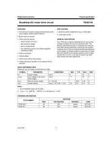
Figure 9: Output speed and torque constant versus phase angle for a 200 W axial flux PM motor [15] As shown in Figure 9, the top speed of the PM motor can be increased to around 50 percent over the baseline top speed. It is expected that the torque constant will also be reduced in the similar manner shown in the Figure 9. The phase current is offset from the optimum 0 angle to generate maximum torque. Too much increase in the phase advance will results in lower amount of torque generation, thus it is necessary to investigate the appropriate control method of phase advanced to generate useful torque output while increasing the operating speed. Figure 10 shows effect of phase advance on motor top speed. Maximum speed test results of the motor operating at different phase angles between -30 and 45 degrees and at maximum supply voltage range between 24 and 48 V. That range been has been used because of minimum voltage required to turn on the Kelly BLDC controller and at higher voltage more than 48, motor become unstable. The maximum speed of the motor is observed to increase with an increase in the phase advanced angle until it reaches maximum speed at around 30 degrees. When the angle is retarded, the maximum motor speed is observed to reduce in a linear manner with almost a constant slope. If all the lines of the graph are extrapolated, the maximum speed of the motor will reach zero rpm as the phase angle reaches -90 degrees during phase retardation of 90 degrees during phase advancement.
7
Figure 10: Effect of Phase Advance on Motor Top Speed These characteristics can be explained by six step phase current waveform advanced angle. As the phase current is advanced from zero position, it will obtain maximum speed at zero loads at 30 degrees advanced angle. As the advanced angle is above 30 degrees, the phase current will respond to negative back EMF, which will results in a gradual increase of opposing torque. Thus, at 90 degrees advanced angle, there will be equivalent amount of clockwise and counterclockwise torque hence the motor will produce a zero amount of net torque. The change of the speed depend on the back EMF constant value, Kv. Different input voltage applied will resulted different Kv value. Figure 11 shows a graph of Kv/V applied as a function of phase angle. It can be observed that Kv has an almost zero slope at zero phase angles.
8
Figure 11: Kv/V versus phase angle Torque is the one of the parameter that be effected when advancing the phase angle. The torque value depend on the torque constant of the motor and it change when phase angle varying. Figure 12 shows the torque constant, Kt versus phase advance angle.
Figure 12: Torque constant, Kt vs phase angle From the shape of graph, it shown that, the value of Kt is high at lower phase advance angle and this Kt value become decrease as phase advance angle increasing and become zero at 90 degree phase advance angle. Similar shape also been shown for retarding angle. This K t related to the torque value as torque value affected by the Kt value. From the speed constant data, Kv that indicate the change of speed and also the torque constant that related to the torque value, a model of torque speed respond has been developed for different phase advance angle as shown in Figure 13. Equation 3 and 4 that are the electrical torque equation been used to establish this model. These equations describe the relation of electrical torque with terminal or input voltage, Vt and the speed of the motor.
9
Figure 13: Torque Speed respond base on Kv/V and Kt data Electrical torque equation [18] Te =
(3)
T = KT*I Te = Electrical torque Vt = Supply voltage KE = Back emf constant ωt = Motor speed KT = Torque constant Rs = Phase resistance I= phase current
(4)
Based on the results the speed of the motor keeps increasing as the phase angle increases until certain point that is about 30 degree advance angle. Beyond this angle, the speed decreases gradually. The optimum angle is determined by considering significant increase of speed at that angle and also considering the current that indicated the lost. The results show as in Figure 13 slope of Kv/V increases from zero degree until 10 degrees. After phase angle 30 degrees, the Kv/V value becomes almost constant. That means the increasing of the speed becomes small and insignificant. For different voltages applied, it shows the back emf constant value, Kv is almost constant at 0.01 rpm/volt. Increasing the speed will affect the motor torque speed respond that caused the output torque of the motor reduced. The actual load level, operating torque, operating speed and motor efficiency will be the determining factor in finding the optimum phase advanced control method.
CONCLUSIONS The increasing in energy prices and environment issue caused several researches in new technology for electric vehicles are established. The heavy and huge in gearbox system cause the high in power over weight ratio for EV. The use of BLDC motor becomes popular in EV application because of small size and high power given. The constant magnetic flux of permanent magnet rotor in BLDC causes the limitation of speed range. Phase advanced control allows the permanent magnet BLDC motor to extend the operating range without the usage of a transmission unit. The absent of a mechanical gearing system will result in higher system efficiency and allows for the usage of smaller motor hence improving the power to weight ratio of the electric drive unit.
10
The phase advance could be established by varying the phase advance angle. The external hall sensor system can be utilized to apply phase advance by manipulating the hall sensors positions. Increasing the phase advance angle caused the speed of the motor increase. The optimum angle determined based on the application used need for high speed or high torque. The external hall sensors system is reliable to utilize in EV application by creating suitable design to deploy it. A suitable control system also needs to be developed to control the hall positions.
ACKNOWLEDGEMENTS The research project is supported under UTP GA scheme, with the small single seat electric vehicle developed under a STIRF research grant for Shell Eco Marathon 2012 and several equipment used are from MOR Energy of UTP.
REFERENCES [1] Gurminder Bedi et.al, Plug-in Electric Vehicles: A Practical Plan for Progress, School of Public and Environmental Affairs, Indiana University, February 2011. [2] K. S. Kuraniet. Al., Household Market for Neighborhood Electric Vehicles in California, Institute of Transportation Studies, University of California, Davis, May 1995. [3] S. L. Herman, ‘Electric Motor Control’, Cengage Learning, 2009. [4] Michael T. DiRenzo, Switched Reluctance Motor Control – Basic Operation and Example Using the TMS320F240, Application Report (SPRA420A), Texas Instruments, February 2000. [5] Han Kong, Jinglin Liu, Guangzhao Cui, Study on Field-weakening Theory of Brushless DC Motor Based on Phase Advance Method, 2010, International Conference on Measuring Technology and Mechatronics Automation, 978-0-7695-3962-1/10 IEEE 2010 [6] X. Luo, D. Qin, T.A. Lipo, A Novel Two Phase Double Salient Permanent Magnet Motor’, Wisconsin Electric Machines and Power Electronics Consortium, 1996. [7] Chun-Lung Chiu, Yie-Tone Chen, Yu-Hsiang Shen, and Ruey-Hsun Liang, An Accurate Automatic PhaseAdvance Adjustment of Brushless DC Motor, IEEE Transactions on Magnetics, Vol. 45, NO0033-2097, R. 88 NR 4a/2012 [8] Shinn-Ming Sue, Kun-Lin Wu, Jhih-Sian Syu, and Kuo-Cheng Lee,’ A Phase Advanced Commutation Scheme for IPM-BLDC Motor Drive, IEEE 978-1- 4244-2800-7/09, 2009. [9] M Ehsani, Y Gao, A Emadi, Modern Electric, Hybrid and Fuel Cell Vehicles: Fundamentals, Theory and Design, CRC Press, 2nd edition, 2010. [10] H E Jordan, Energy Efficient Electric Motors and Their Applications, Springer, 2nd Edition, 1994. [11] Z Rahman, M Ehsani, K L Butler, An Investigation of Electric Motor Drive Characteristics for EV and HEV Propulsion Systems, 2000 Future Transportation Technology Conference, SAE 2000-01-3062, Society of Automotive Engineers, 2000. [12] J German, Vehicle Technology: How Far and How Fast’, Transportation Efficiency in 21st Century, The International Council on Clean Transportation, November 2010. [13] S Abourida, J Belanger. Real Time Platform for the Control Prototyping and Simulation of Power Electronics and Motor Drives, Proceedings of the 3rd International Conference on Modeling, Simulation and Applied Optimization, 2009. [14] D.C.Hanselman, Brushless Permanent Magnet Motor Design, The Writers' Collective, 2003. [15] M Syaifuddin Mohd, Mechanical Field Weakening of Axial Flux PM Motor by Manipulation of Rotor- Stator Attractive Force, PG Symposium Progress Report,Mechanical Engineering Department, Universiti Teknologi PETRONAS, December 2012 11