Original Article
Effect of placement angle on the stability of loaded titanium microscrews in beagle jaws Zhenrui Xu*a; Yeke Wub; Lixing Zhaoc; Yuqiao Zhoub; Xing Weib; Na Tangb; Xiaoxia Fengb; Tian Tanga; Zhihe Zhaod ABSTRACT Objective: To evaluate the effect of insertion angle on stability of loaded titanium microscrews in beagle jaws. Materials and Methods: Forty-eight microscrews were inserted at four different angles (30u, 50u, 70u, and 90u) into the intraradicular zones of the mandibular first molars and third premolars of 12 beagles and immediately loaded with a force of 2 N for 8 weeks. Microcomputed tomography (micro-CT) and biomechanical pull-out tests were used to assess osseointegration of the interface. Results: All micro-CT parameters and maximum pull-out force (FMAX) of the microscrews were affected by insertion angles of microscrews. Higher micro-CT parameters and FMAX were seen for implants inserted at angles between 50u and 70u (P , .05). Excessive oblique and vertical insertion angles resulted in reduced stability (P , .05). Conclusion: An insertion angle of 50u to 70u is more favorable than excessive oblique or vertical angles to achieve stability of microscrews. (Angle Orthod. 2013;83:659–666.) KEY WORDS: Insertion angle; Osseointegration; Microscrews; Microcomputed tomography; Biomechanics
dentistry.2,3 The application of dental implants in orthodontics to provide additional temporary intraoral anchorage has shown encouraging results.4 In contrast to traditional dental implants, which require time for osseointegration and more anatomic space, microscrews (1.0 to 1.2 mm in diameter and 6 mm in length) can be placed in more varied locations and loaded immediately after insertion. Microscrews also have the advantages of smaller size, simpler placement and removal surgeries, greater cost effectiveness, and less reliance on patient cooperation.5 To date, microscrews have been used extensively for maximal anchorage to assist with tooth movement in orthodontic and preprosthetic treatment.6,7 However, in clinical applications, they may loosen easily or even fall out; therefore, microimplant stability is a frequent topic of investigation.8,9 The establishment of reliable osseointegration for a microscrew is determined not only by the implant itself, but by parameters such as surgical technique and loading conditions.10 Meanwhile, clinical interest in the loading conditions of microscrews, including healing time before loading and loading period, magnitude, and direction, is great, as the related data have been extensively reported.11,12 However, few studies have focused on the direction of the applied forces. Because in the present study, the orthodontic forces are parallel
INTRODUCTION Bra˚nemark et al.1 introduced the term osseointegration to describe the stable fixation of titanium in bone tissue. Since then, many studies have been conducted to investigate the application of titanium implants in a Lecturer, State Key Laboratory of Oral Diseases, Department of Orthodontics, West China School of Stomatology, Sichuan University, Chengdu, PR China. b PhD Candidate, State Key Laboratory of Oral Diseases, Department of Orthodontics, West China School of Stomatology, Sichuan University, Chengdu, PR China. c Lecturer and Research Assistant, State Key Laboratory of Oral Diseases, Department of Orthodontics, West China School of Stomatology, Sichuan University, Chengdu, PR China. d Professor, State Key Laboratory of Oral Diseases, Department of Orthodontics, West China School of Stomatology, Sichuan University, Chengdu, PR China. * The first two authors, Zhenrui Xu and Yeke Wu, contributed equally to this work. Corresponding author: Zhihe Zhao, State Key Laboratory of Oral Diseases, Department of Orthodontics, West China School of Stomatology, Sichuan University, #14, section 3, Renminnan Rd, Chengdu 610041, PR China (e-mail:
[email protected])
Accepted: November 2012. Submitted: August 2012. Published Online: December 10, 2012 G 2013 by The EH Angle Education and Research Foundation, Inc. DOI: 10.2319/081612-660.1
659
Angle Orthodontist, Vol 83, No 4, 2013
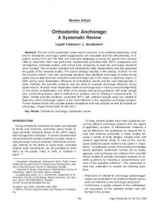
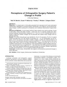
660 to the cortical bone surface of beagle jaws, the insertion angle of microscrews will influence the direction of orthodontic forces. Previously, Park et al.12 introduced oblique rather than perpendicular insertion of implants to prevent root damage. It has been proven repeatedly that slightly oblique insertion angles lead to better osseointegration of the bone-implant interface and improved primary stability in various models, including artificial bone blocks, nasal bones of rabbit, and ilium bone segments of pig.13–15 A recent study reported that changing the insertion angle from 90u to 45u increased the cortical bone-to-implant contact by 47% and generally enhanced implant stability in humans.16 In the dog mandible, insertion at less than 90u to the bone surface was also suggested to reduce the likelihood of root contact.17 In contrast, most in vitro tests have placed microscrews perpendicular to the artificial bone surface (ie, 90u, or vertical).18–21 Therefore, it is necessary to investigate the actual effect of insertion angle on the stability of microscrews. Moreover, we have reported that different placement angles influenced the stability of microscrews in a beagle tibia model.22 However, the tibiae are different from jaws with regard to bone density, cortical thickness, trabecular-cortical bone ratio, and other factors. Thus, the experimental data from a tibia model cannot be directly extrapolated to the human jaws. This study was designed to investigate the impact of placement angle on the stability of loaded microscrews. Microcomputed tomography (micro-CT) and pull-out tests were used to evaluate stability and integration of the microscrews. MATERIALS AND METHODS Animals and Microscrews Placement Twelve male beagles (24 months of age; about 12.5 kg in weight) were supplied by the Experimental Animal Center of Sichuan University in Chengdu, China. The veterinary records indicated that all beagles were healthy and had no malocclusion or periodontal diseases. All beagles in this study were handled according to an experimental protocol approved by the Bioethics Committee of Sichuan University, China. The beagles were randomly assigned to four groups according to different microscrew insertion angles (a 5 30u, 50u, 70u, and 90u), with each beagle receiving two pairs of microscrews (Figure 1). All surgical procedures were performed under systemic (1 mg/kg ketamine and 2 mg/kg intramuscular xylazine; North China Company, Shi Jiazhung, China) and local (2% lidocaine with 1:80,000 epinephrine) anesthesia. Forty-eight microscrews (6 mm long, 1.6 mm diameter; Medicon Angle Orthodontist, Vol 83, No 4, 2013
XU, WU, L. ZHAO, ZHOU, WEI, N. TANG, FENG, T. TANG, Z. ZHAO
Figure 1. Diagram of the microscrews inserted at different angles; a indicates the angle between the long axis of the microscrews and the bone surface.
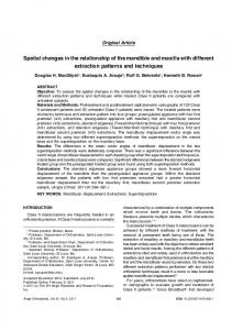
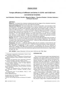
Company, Tuttlingen, Germany) were prepared for implantation. With reference to a map of safe zones for microscrew implantation in beagle jaws,23 the intraradicular zones of the mandibular first molar (M1) and third premolar (P3) were chosen as experimental sites for microscrew insertion. The mandible was surgically exposed by blunt dissection. All microscrews were inserted with the same drilling method. First, a guide drill was used to establish the insertion site and angle (Figure 2A). Then the microscrews were inserted with a hand-held screwdriver until the microscrew collar was level with the bone. On each side of the mandible, two microscrews were inserted at angle a or 180u 2 a. The screws were immediately loaded with a force of 2 N via a closed-coil spring between the implants (Figure 2B). Specimen Preparation After 8 weeks of loading, the animals were killed with a lethal dose of pentobarbital. Mandibles with microscrews were removed and carefully sectioned into small blocks, each of which contained one microscrew surrounded by at least 5 mm of bone without soft tissue. All bone/implant blocks were subsequently transferred into 10% buffered formalin at 4uC for fixation. Micro-CT Assessment After 2 weeks of fixation, the specimens were prepared for micro-CT investigation. The proximal 5 mm of the bone were examined with a micro-CT imaging system (CT80, Scanco Medical, Bassersdorf, Switzerland). The scan conditions were 70 kV, a 300ms integration time, and 114 mA. The voxel size was 1024 3 1024 pixels. One thousand microtomographic slices were acquired at a spatial nominal resolution of 20 mm. The images were reconstructed and analyzed with the software CT-An (CT-Analyser, Skyscan, Kontich, Belgium) for detailed qualitative and quantitative three-dimensional evaluation. The titanium and
661
EFFECT OF INSERTION ANGLE ON MICROSCREWS STABILITY
Figure 2. (A) Microscrews are inserted obliquely (relative to the bone surface) with a hand-held screwdriver. (B) Implants have been placed and loaded with a force of 2 N via a closed-coil spring between the microscrews. (C) Material testing system (Instron 5565, Instron Corporation, Norwood, Mass). (D) Specimen embedded in acrylic resin and prepared for pull-out testing.
mineralized tissue were segmented from each other and from the bone marrow, including that in the immediate vicinity of the implant, via application of a multilevel threshold procedure.24 The peri-implant trabecular bone (PIB) volume of interest included the entire trabecular compartment between the crosssectional planes 1.0 mm proximally and 1.0 mm distally from the implant’s longitudinal axis. The following morphometric parameters were calculated in the PIB: bone density (BV/TV), trabecular thickness (Tb.Th), trabecular number density (Tb.N), and intersection surface (IS). Osseointegration (OI) was also calculated as the ratio of IS to the surface area of the intraosseous mini-implant. Biomechanical Testing Protocol To assess the biomechanical influence of insertion angle, pull-out testing was performed with a materials testing system (Instron 5565, Instron Corporation, Norwood, Mass) (Figure 2C). Six bone/implant blocks in each group were selected after 48 hours of fixation and were embedded in polymethylmethacrylate (Heraeus Dental Products, Hanau, Germany), with the
microscrew heads exposed so that the testing machine could tightly clamp the block and pull the microscrew heads with a jig. Each specimen was modified and fixed to ensure that it was vertical to the longitudinal axis of the microscrew (Figure 2D). For pull-out testing, microscrews were aligned with the axis of the testing machine to ensure that no bending moment was created during the test and that only axial pull-out strength would be recorded. The microscrews were pulled out at a crosshead speed of 0.05 mm/s. The applied load was monitored, and the peak load at extraction (FMAX) was recorded. Statistical Analysis Statistical analysis was carried out with the Statistical Package for Social Sciences (Windows version 11.0, SPSS Inc, Chicago, Ill). Analysis of variance was used to evaluate the differences in morphometric and biomechanical parameters of the four groups (30u, 50u, 70u, and 90u). The Student-Newman-Keuls test was used to investigate the differences between groups. P values less than .05 were considered to indicate statistical significance. Spearman or Pearson Angle Orthodontist, Vol 83, No 4, 2013
662
XU, WU, L. ZHAO, ZHOU, WEI, N. TANG, FENG, T. TANG, Z. ZHAO
was slightly loose, and the others remained stable throughout the study. Micro-CT Findings
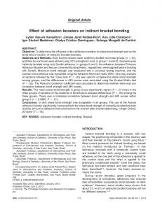
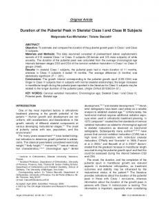
Figure 3. Periapical film after implant placement shows a tooth root (white arrow), intraradicular zone (grey arrow), and inserted microscrew (black arrow).
correlation coefficients were calculated to assess the relationships between insertion angle, OI, and FMAX. This coefficient test was used at the level of P , .05. RESULTS We observed a 100% survival rate of microscrews for all groups. One microscrew inserted at a 30u angle
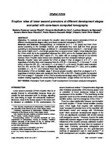
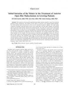
The results demonstrated that insertion angle affected the measured micro-CT parameters, including OI and PIB density (Figure 4). Quantitatively, when the 50u, 70u, and 90u groups were compared with the 30u group, there was a statistically significant increase in OI (P , .05). Both the 50u and 70u groups showed statistically significantly higher OI vs the 90u group (P , .05). A comparison of the 50u and 70u groups showed no significant differences between them (P . .05) (Figure 5A). With respect to PIB, all groups showed significant differences, except for the comparison of the 50u group with the 70u group in BV/TV (Figure 5B). With respect to Tb.Th, the 50u, 70u, and 90u groups showed 237%, 259%, and 207% higher Tb.Th values, respectively, compared with the 30u group (P , .05) (Figure 5C). Tb.N showed the same pattern as OI, with higher values in the 50u and 70u groups (P , .05) (Figure 5D). The morphometric parameter that had the strongest correlation with OI was IS, which assessed the contact area between
Figure 4. Peri-implant trabecular bone. Representative specimens with median trabecular bone volume density values. (A) A 30u specimen. (B) A 50u specimen. (C) A 70u specimen. (D) A 90u specimen. Angle Orthodontist, Vol 83, No 4, 2013
EFFECT OF INSERTION ANGLE ON MICROSCREWS STABILITY
663
Figure 5. Measurements of bone around the microscrews inserted at different angles. (A) Osseointegration (OI). (B) Trabecular bone volume density (BV/TV). (C) Trabecular thickness (Tb.Th). (D) Trabecular number density (Tb.N). (E) Intersection surface (IS). (F) Maximum force (Fmax) of pull-out test. Data are means 6 standard deviations obtained at different insertion angles. Letters indicate significant differences between the group that the cell represents and the group that the letter represents.
Angle Orthodontist, Vol 83, No 4, 2013
664
XU, WU, L. ZHAO, ZHOU, WEI, N. TANG, FENG, T. TANG, Z. ZHAO
Table 1. Correlationsa Among Insertion Angles, Osseointegration (OI), and Maximum Pull-out Force (FMAX) Different angle (u)
r 5 0.319 P 5 .036*
Different angle (u) OI (%)
OI (%)
r 5 0.319 P 5 .036*
FMAX (N) r P R P
5 0.334 5 .027* 5 0.612 , .001**
a r indicates Spearman correlation coefficient; R, Pearson correlation coefficient. * P , .05; ** P , .01.
bone and microscrews. Its value in the 30u group was 2.83 mm2, and the 50u group had a higher value (5.96 mm2) than the 30u group (P , .05). The IS value of the 70u group (6.3 mm2) was significantly higher than that of the 50u group (P , .05). However, those of the 90u group (4.67 mm2) were significantly lower than those of the 50u and 70u groups (P , .05) (Figure 5E). Biomechanical Results The FMAX values varied with the different angles of insertion. When the 50u, 70u, and 90u groups were compared with the 30u group, there was a statistically significant increase in FMAX (P , .05). Both the 50u and 70u groups showed a statistically significant increase in FMAX vs the 90u group (P , .05). No significant difference was seen between the 50u and 70u groups (P . .05) (Figure 5F). Correlations All pairs of parameters in the correlation test demonstrated statistically significant differences (P , .05). Both OI and FMAX were correlated with different angles, but the correlation coefficients were low (r 5 0.319 and 0.334, respectively), denoting weak correlations. This suggests that the extent to which implantbone units gained biomechanical strength with the change of angle was somewhat limited. The correlation coefficient between OI and FMAX was 0.612, indicating a moderate correlation. These data indicated that these measurements might be related (Table 1). DISCUSSION Anchorage is the resistance to unwanted tooth movement, and good anchorage is critical in orthodontics.25 In recent years, microscrews have been widely used for absolute anchorage during orthodontic therapy.23 The loading force is directly applied to the screw head through a coil spring or elastic. Orthodontic loads are parallel to the surface of the cortical bone12; therefore, when the insertion angle of microscrews was changed, the angle between the Angle Orthodontist, Vol 83, No 4, 2013
load direction and the axis of the microscrews was also altered. Clinically, orthodontists tend to place the apices of microscrews toward the apices of adjacent teeth, but in our study, this approach was not used. Instead, we inserted the microscrews with their apices directed mesiodistally. The reasons were as follows: (1) this insertion direction satisfied the aim of our study and reduced the number of animals that needed to be used; (2) it was beneficial for controlling the loading magnitude and period, preventing uneven stress distribution on coil springs as a result of deformation; and (3) it eased the selection of insertion sites and prevented damage to the coil springs via chewing. Therefore, we inserted the microscrews with the apices pointing mesiodistally, but apically in operation. Moreover, to avoid damaging the adjacent dental roots, we selected mandibular M1 and P3 intraradicular zones as insertion sites, based on data from previous studies.23 Nondestructive micro-CT analysis allows clinicians to comprehensively assess the interface between bone and implants in three dimensions within the same specimen, thereby reducing the number of animals needed for preclinical trials. The mechanical stability of titanium implants has been reported to depend on the amount of peri-implant bony tissue.26 The findings of this study suggest that higher micro-CT parameters, including OI, BV/TV, Tb.Th, Tb.N, and IS, were observed in the 50u and 70u groups. Pull-out testing, as a method of biomechanical research, has been widely used for evaluating implants’ retentive strength in orthopedics, neurosurgery, and maxillofacial surgery.27 In this study, the microscrews we used could effectively transform a pull-out force into a shear force, thus transferring the latter to the contacting bone. The data of the present study revealed that the average values of FMAX for implants with very oblique and vertical insertion angles were significantly lower than for screws inserted at slightly oblique insertion angles. The comparison between extremely obliquely and vertically inserted microscrews showed that vertical insertion was better than extremely oblique insertion. We also analyzed the relationship between several morphometric and biomechanical parameters and the insertion angles of microscrews. The results indicated that OI and FMAX of pull-out tests correlated with each other to some extent; this suggests that these two sets of data might be related. Using histomorphometric and biomechanical analysis, we demonstrated that microscrew stability was affected by different insertion angles. Slightly oblique insertion was beneficial to microscrew stability, while very oblique or vertical insertion was harmful. The
EFFECT OF INSERTION ANGLE ON MICROSCREWS STABILITY
665
reasons may be as follows: (1) Although the depth of slightly oblique microscrews was reduced compared to that of fully perpendicular inserted microscrews, they engaged with a greater amount of cortical bone when inserted obliquely, and the ratio of cortical to cancellous bone is known to be very important for implant stability28; (2) the bending force exerted on the slightly oblique microscrews was lower, and an axial force was produced that might promote microscrew-to-bone OI; (3) because extensive microdamage may impair microscrew stability during OI, a very oblique inserted angle, which may induce more severe cortical bone microdamage than a slightly oblique angle, could lead to weaker stability29; and (4) the insertion depth declined severely for the very obliquely inserted microscrews. In conclusion, to better resist orthodontic forces and ensure osseointegration of loaded microscrews, an insertion angle ranging from 50u to 70u may be advisable. Both very oblique and vertical insertion angles may result in reduced stability of loaded microscrews.
region for orthodontic anchorage. Am J Orthod Dentofacial Orthop. 2003;124:373–378. Szmukler-Moncler S, Salama H, Reingewirtz Y, Dubruille JH. Timing of loading and effect of micromotion on bonedental implant interface: review of experimental literature. J Biomed Mater Res. 1998;43:192–203. Zhao LX, Xu ZR, Yang Z, et al. Orthodontic mini-implant stability in different healing times before loading: a microscopic computerized tomographic and biomechanical analysis. Oral Surg Oral Med Oral Pathol Oral Radiol Endod. 2009;108:196–202. Park HS, Jeong SH, Kwon OW. Factors affecting the clinical success of screw implants used as orthodontic anchorage. Am J Orthod Dentofacial Orthop. 2006;130:18–25. Holm L, Cunningham SJ, Petrie A, et al. An in vitro study of factors affecting the primary stability of orthodontic miniimplants. Angle Orthod. 2012 May 7. [Epub ahead of print] Inaba M. Evaluation of primary stability of inclined orthodontic mini-implants. J Oral Sci. 2009;51:347–353. Wilmes B, Su YY, Drescher D. Insertion angle impact on primary stability of orthodontic mini-implants. Angle Orthod. 2008;78:1065–1070. Laursena MG, Melsen B, Cattaneoc PM. An evaluation of insertion sites for mini-implants. Angle Orthod. 2012 Aug 27. [Epub ahead of print] Salmo´ria KK, Tanaka OM, Guariza-Filho O, et al. Insertional torque and axial pull-out strength of mini-implants in mandibles of dogs. Am J Orthod Dentofacial Orthop. 2008; 133:790.e15–22. Cho KC, Baek SH. Effects of predrilling depth and miniimplant shape on the mechanical properties of orthodontic mini-implants during the insertion procedure. Angle Orthod. 2012;82:618–624. Lim SA, Cha JY, Hwang CJ. Insertion torque of orthodontic miniscrews according to changes in shape, diameter and length. Angle Orthod. 2008;78:234–240. Brinley CL, Behrents R, Kim KB, Condoor S, Kyung HM, Buschang PH. Pitch and longitudinal fluting effects on the primary stability of miniscrew implants. Angle Orthod. 2009; 79:1156–1161. Migliorati M, Signori A, Silvestrini Biavati A. Temporary anchorage device stability: an evaluation of thread shape factor. Eur J Orthod. 2012;34:582–586. Zhao L, Xu Z, Wei X, Zhao Z. Effect of placement angle on the stability of loaded titanium microscrews: a microcomputed tomographic and biomechanical analysis. Am J Orthod Dentofacial Orthop. 2011;139:628–635. Zhao L, Xu Z, Yang Z, et al. Quantitative research using computed tomographic scanning of beagle jaws for determination of safe zones for micro-screw implantation. Ann Anat. 2009;191:379–388. Gabet Y, Muller R, Regev E, et al. Osteogenic growth peptide modulates fracture callus structural and mechanical properties. Bone. 2004;35:65–73. Salmoria KK, Tanaka OM, Guariza-Filho O, Camargo ES, de Souza LT, Maruo H. Insertional torque and axial pull-out strength of mini-implants in mandibles of dogs. Am J Orthod Dentofacial Orthop. 2008;133:790:e15–22. Ducheyne P, Hench LL, Kagan A, et al. Effect of hydroxyapatite impregnation on skeletal bonding of porous coated implants. J Biomed Mater Res. 1980;14:225–237. Soncini M, Rodriguezy Baena R, et al. Experimental procedure for the evaluation of the mechanical properties of the bone surrounding dental implants. Biomaterials. 2002; 23:9–17.
10.
11.
12.
13.
14. 15.
16.
17.
ACKNOWLEDGMENT This work was supported by grants from the National Nature Science Foundation of China (No. 30470436, No. 10572160).
REFERENCES 1. Bra˚nemark P, Breine U, Adell R. Intraosseous anchorage of dental prostheses. I. Experimental studies. Scand J Plast Reconstr Surg. 1969;3:81–100. 2. Albrektsson T, Dahl E, Enborm L. Osseointegrated oral implants: a Swedish multicenter study of 8139 consecutively inserted Nobelpharma implants. J Periodontol. 1988;59: 287–296. 3. Bra˚nemark P, Hansson B, Adell R, et al. Osseointegrated implants in the treatment of the edentulous jaw: experience from a 10-year period. Scand J Plast Reconstr Surg Suppl. 1977;16:1–132. 4. Albrektsson T, Bra˚nemark PI, Hansson HA, Lindstro¨m J. Osseointegrated titanium implants. Requirements for ensuring a long-lasting, direct bone-to-implant anchorage in man. Acta Orthop Scand. 1981;52:155–170. 5. Huang LH, Shotwell JL, Wang HL. Dental implants for orthodontic anchorage. Am J Orthod Dentofacial Orthop. 2005;127:713–722. 6. Papadopoulos MA, Tarawneh F. The use of miniscrew implants for temporary skeletal anchorage in orthodontics: a comprehensive review. Oral Surg Oral Med Oral Pathol Oral Radiol Endod. 2007;103:e6–15. 7. Deguchi T, Takano-Yamamoto T, Kanomi R, et al. The use of small titanium screws for orthodontic anchorage. J Dent Res. 2003;82:377–381. 8. Cheng S, Tseng I, Lee J, Kok S. A prospective study of the risk factors associated with failure of mini-implants used for orthodontic anchorage. Int J Oral Maxillofac Implants. 2004; 19:100–106. 9. Miyawaki S, Koyama I, Inoue M, et al. Factors associated with the stability of titanium screws placed in the posterior
18.
19.
20.
21.
22.
23.
24.
25.
26.
27.
Angle Orthodontist, Vol 83, No 4, 2013
666 28. Miyamoto I, Tsuboi Y, Wada E, Suwa H, Iizuka T. Influence of cortical bone thickness and implant length on implant stability at the time of surgery—clinical, prospective, biomechanical, and imaging study. Bone. 2005;37:776–780.
Angle Orthodontist, Vol 83, No 4, 2013
XU, WU, L. ZHAO, ZHOU, WEI, N. TANG, FENG, T. TANG, Z. ZHAO
29. Frost HM. A brief review for orthopedic surgeons: fatigue damage (microdamage) in bone (its determinants and clinical implications). J Orthop Sci. 1998;3:272– 281.