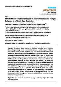
International Journal of Mechanical Engineering and Technology (IJMET) Volume 8, Issue 10, October 2017, pp. 484–492, Article ID: IJMET_08_10_053 Available online at http://www.iaeme.com/IJMET/issues.asp?JType=IJMET&VType=8&IType=10 ISSN Print: 0976-6340 and ISSN Online: 0976-6359 © IAEME Publication
Scopus Indexed
EFFECT OF PROCESS PARAMETERS ON MICROSTRUCTURE AND MECHANICAL PROPERTIES OF FRICTION STIR WELDED ZE42 MAGNESIUM ALLOY A.K.Darwins Research Scholar, Department of Mechanical Engineering Noorul Islam University, Kumaracoil, India M.Satheesh Assistant Professor, Department of Mechanical Engineering Noorul Islam University, Kumaracoil, India ABSTRACT In this study effect of process parameters on Friction stir welded Magnesium ZE42 alloy have been investigated. Friction stir welding is carried out at different welding rotational speeds of 950 rpm, 1050 rpm, 1150 rpm and 1500 rpm and with tool of H13 steel material at a constant feed rate of 30 mm/min. It is witnessed that the effect of tool material and feed rate on microstructure and mechanical properties of that the joint fabricated using tool material at a welding rotational speed of 1100 rpm and 30mm/min obtained higher mechanical properties as compared to those of 950 rpm, 1150 rpm and 1500 rpm and also to those of tool material. Keyword: Friction Stir Welding; Magnesium Alloy; Mechanical properties; welding speed Cite this Article: A.K.Darwins and M.Satheesh, Effect of Process Parameters on Microstructure and Mechanical Properties of Friction Stir Welded Ze42 Magnesium Alloy, International Journal of Mechanical Engineering and Technology 8(10), 2017, pp. 484–492. http://www.iaeme.com/IJMET/issues.asp?JType=IJMET&VType=8&IType=10
1. INTRODUCTION In recent years engineering metals like magnesium alloys are developing as important engineering materials, especially in aerospace and automobile sectors, because of their low density, high strength-to-weight ratio and high stifling capacity [1]. While, at present, magnesium alloys are mainly used as castings, their use in wrought form is expected to rapidly increase in the coming years. With this, joining of magnesium alloys will become a more frequent necessity. Also Friction stir welding (FSW), being a solid-state process, can
http://www.iaeme.com/IJMET/index.asp
484
[email protected]
A.K.Darwins and M.Satheesh
potentially overcome many of the problems associated with fusion welding of magnesium alloys. FSW is now a matured welding process for aluminium alloys. Unlike these high strength materials, which place unrealistically high demands on friction stir tooling and machinery, magnesium alloys, given their low strength and melting point, are as amicable for FSW as aluminium alloys [2]. Therefore, FSW can, in principle, be as successful for magnesium alloys as it is for aluminium alloys. This led to the friction stir welding of magnesium-base alloys has not been studied extensively as aluminum but some results have been reported Nagasawa et al. [3] have friction stir welded 6-mm thick AZ31 plates with a rotational speed of 1750 rpm and a transfer speed of 88 mm/min and found out that the mechanical strength of the weld was comparable to the base material but with only half of the ductility. Park et al [4] also studied FSW on 6-mm mg plates at 1230 rpm and 90 mm/min which showed a much lower yield strength and elongation, and slightly lower ultimate tensile strength of the weld from the transverse tensile test compared with the base material. Nakata et al [5] studied the optimal processing conditions for FSW of 2-mm thixomoulded sheet. An increase of 38 to 50% of the tensile strength in the weld could be obtained over base material with a rotational speed between 1240 rpm to 1750rpm and transverse speed of 50mm/min. They contributed to the increase of strength due to the fine recrystallization structure of 2-5 µm. Padmanabham et al. [6] studied the tool material effect on the friction stir welding of magnesium alloy. Tool materials such as stainless steel, high speed steel, and armour steel, mild steel and high carbon steel were used. It was concluded that the joints fabricated by high carbon steel tool with 66 HRC, threaded pin profile and a shoulder diameter of 18mm (D/d=3) exhibited superior tensile properties compared to their contradict parts. The tool material which possesses higher hardness may generate much higher heat due to higher coefficient of friction. If this is the case, high speed steel might have generated high heat than the stainless steel. Due to the high thermal conductivity of high speed steel much heat might have developed at the tool shank resulting in the poor mechanical properties compared to those of high carbon steel. Most of the published papers were focused on the effects of rotational speed and translational speed on the stirred zone properties of magnesium-base alloy [7]. It has been shown that higher hardness values (72 Hv) can be obtained compared to base material hardness (68 Hv) at a certain combination of rotational and translational speeds. The hardness value decreased as the rotational speed increased in the range of 1200 rpm to 2000rpm and at 30 in/min translational speed. On the other hand the hardness value increased as the translational speeds increased in the range 381 mm/min to 760 mm/min and at 1200 rpm rotational speed. However, there is some result reported in the literature related to combination of Tool materials and welding speed, which influence on mechanical properties of FSWed ZE42 Mg alloy [8]. In this present investigation, effect of welding rotational speed (i.e. 950 rpm, 1050 rpm, 1150 rpm and 1500 rpm) and tool material on (H13) mechanical properties of friction stir welded of ZE42 Magnesium alloy of the mechanical properties and microstructure are evaluated for its excellent formability and widely considered for use in aerospace and automobile industries.
2. EXPERIMENTAL PROCEDURE The FSW process includes three phenomena: heating, plastic deformation, and forging. A non-consumable rotating tool, consisting of a probe and shoulder, is plunged into the materials to be joined and then traverses the joint line. Heat is generated through both friction and plastic deformation of the welded material. 4 mm thickness ZE42 magnesium alloy were cut to the required dimensions (150mm×60mm×5mm) [9]. The schematic diagram of mg
http://www.iaeme.com/IJMET/index.asp
485
[email protected]
Effect of Process Parameters on Microstructure and Mechanical Properties of Friction Stir Welded Ze42 Magnesium Alloy
plates used for FSW is shown in Fig.1. The chemical composition of base metal is presented in Table 1.
Figure 1 The schematic diagram of ZE42 Mg alloy plates used for FSW Table 1 Chemical composition (wt %) of base metal of ZE42 magnesium alloy Al 3.0
Mn 2.1
Zn 1.2
Cu 0.06
Ni 0.005
Si 0.2
Fe 0.005
Mg Balance
The initial joint configuration was obtained by securing the plates in position using mechanical clamps. The direction of welding is normal to the rolling direction and single pass FSW used to fabricate the joints. The diameter of the tool shoulder (D) is 16 mm and that of the insert pin diameter (d) and pin length (L) are 5mm and 3.7mm respectively. The schematic diagram of Tool geometry is shown in Figure 2. Table 2 FSW process parameters and tool nomenclature Rotational speed(rpm) Welding speed(mm/min) Pin length(mm) Tool shoulder diameter(mm) Axial force(KN) Tilt angle Pin diameter(mm) Shoulder length(mm) D/d Ratio of tool Tool materials Tool Profile
950,1050,1150,1500 30 3.7 16 5 2 5 40 3.0 H13 Stainless Steel Taper with Threaded
The FSW parameters such as tool rotational speeds and travelling speed were 950 rpm, 1050 rpm, 1150rpm, and 1500 rpm with 30mm/min respectively. The tool onward tilted an angle of 2º and a vertical load of 5KN is applied. The FSW process parameters and tool nomenclature are presented in Table 2. The process is carried out on a vertical milling machine using 10hp and 3000rpm. For various testing the required dimensions of the specimens were cut from the region under the tool shoulder by wire EDM. The macrographs of milling machine are shown in Fig.3. Hardness properties were measured on the cross section of the FSWed joint perpendicular to
http://www.iaeme.com/IJMET/index.asp
486
[email protected]
A.K.Darwins and M.Satheesh
the processing direction by using Vickers hardness tester utilizing a 250g load for 20s. The schematic diagram of micro hardness survey is shown in Fig.4. The flat tensile specimens were prepared as per ASTMB557M-10 standard to evaluate yield strength, tensile strength, and elongation of the joints.
Figure 2 The schematic diagram of Tool geometry
Figure 3 The macrographs of Friction stir welding
The schematic diagram of the tensile specimen is shown Fig.5. Tensile test was carried out in a 50KN electromechanical-controlled universal testing machine using blue star maker. Tensile testes of as-received Mg alloy and the FSWed joint were determined at ambient temperature and three specimens were machined from each joint and the average was described. Micro structural analysis was carried out using a light optical microscope
http://www.iaeme.com/IJMET/index.asp
487
[email protected]
Effect of Process Parameters on Microstructure and Mechanical Properties of Friction Stir Welded Ze42 Magnesium Alloy
incorporated with an image analysing at high magnification to estimate the weight percentage of elements.
Figure 4 The schematic diagram of micro hardness survey
Figure 5 The schematic diagram of the tensile specimen
The impact test specimens were prepared according to the ASTM: E23-06 standard and evaluate the impact toughness of the weld metal and stir zone, and hence the notch was placed (machined) at the weld metal (weld center) as well as in the SZ. Impact testing was conducted at room temperature using a pendulum type impact testing machine with maximum capacity of 300 J.
3. RESULT AND DISCUSSIONS 3.1. Effect of welding speed on mechanical properties 3.1.1 Hardness
Figure 6 Hardness properties of FSW processed ZE42 Mg alloy at different rotational speeds
The hardness was measured across the weld in the heat zone using micro hardness testing values are presented in Figure 6. The hardness of unweld base metal is 70 Hv. Vickers micro hardness is measuring along the mid thickness line of cross section of the joint. The joint
http://www.iaeme.com/IJMET/index.asp
488
[email protected]
A.K.Darwins and M.Satheesh
fabricated with the rotational speed of 1150 rpm, welding speed of 30 mm/min, recorded higher hardness (72Hv) in the stir zone, and this is also one of the reasons for superior tensile properties of these joints compared to other joints. These are two main reasons for the improved hardness of stir zone. Initially, since the scrap size of stir zone is much finer than that of base metal, grain refinement plays an important role in material strengthening, secondly the small particles of intermetallic compounds are also a benefit to hardness improvement [11]. The joint fabricated with a rotational speed of 1150 rpm with SS tool material exhibited higher hardness 72 Hv in the stir zone compared to other rotational speeds and this is also one of the reasons for superior tensile properties of these joints. Higher tool speed resulted in higher heat generation and this lead to the excessive release of stirred material to the upper surface which results in lower hardness. 3.1.2. Tensile Measurement The effect of tool rotational speed on Mechanical properties such as tensile strength, yield strength and % of elongation of Friction Stir Welded ZE42 magnesium alloy joints are presented in Table 3. In FSW, tool rotation speed results in stirring and mixing of material around the rotating pin which in turn increase the temperature of the metal. It is known that the maximum temperature observed to be a strong function of tool rotation speed [11]. Table 3 Effect of welding speed and tool material on mechanical properties of ZE42 Mg alloy using H13 steel tool material Joint Welding No. Speed (rpm) 1 2 3 4 5
950 1050 1150 1500 Base ZE42
UTS (MPa) 97.12 102.18 107.13 86.45 120
Yield Strength Elongation Hardness Impact Test (%) (Hv) (Joules) (Mpa) 64.41 75.28 74.10 59.52 110
7.2 7.2 8.5 8.5 10
62 68 72 58 70
6 6 5 5 6
It appears to be the most significant process variable since it is tends to influence the transitional velocity. At lower rotational speed (950rpm), the ultimate tensile strength, yield strength and % of elongation of FSW joints is lower. When the rotational speed is increased from 950rpm, correspondingly the ultimate tensile strength also increases and reaches a maximum at 1150 rpm made of H13 tool material. If the rotational speed is increased above 1200 rpm, the tensile strength of the joint decreased. Higher tool rotational speed (1500 rpm) usually resulting in higher heat input per unit length and slower cooling rate in the FSW zone causes excessive grain growth, which subsequently lead to lower tensile properties of the joints. The tensile properties of the ZE42 magnesium alloys are shown in fig.7. A higher rotational speed also causes expensive release of stored materials to the upper surface, which produces micro-voids in the stir zone and this may be one of the reasons for lower tensile properties of the joints, even at lower rotational speed (950 rpm) results in lower tensile properties which is due to lack of stirring and lower heat input per unit length that leads to insufficient plasticization. It is observed that the joint fabricated at a tool rotational speed of 1150 rpm made of tool material exhibited higher tensile strength, yield strength and % of elongation and this may be due to optimum heat generation which is sufficient to cause free flow of plasticized material and adequate mechanical working [12].
http://www.iaeme.com/IJMET/index.asp
489
[email protected]
Effect of Process Parameters on Microstructure and Mechanical Properties of Friction Stir Welded Ze42 Magnesium Alloy
Figure 7 Histogram image of tensile properties of the ZE42 magnesium alloys
3.1.3. Impact Test The impact toughness of unwelded base metal is 6J. However, the impact toughness of FSW joint with notch placed at the SZ region and reached maximum 6J at 1050 rpm, compared to the other rotational speeds. Charpy impact toughness of FSW joint was evaluated and presented in Table 3. It is observed that the joint fabricated at a tool rotational speed of 1050 rpm made of tool material exhibited higher impact strength 6 joules and this may be due to optimum heat generation which is sufficient to cause free flow of plasticized material. 3.1.4 Microstructure The optical micrographs taken at stir zone of FSW of all the joints are shown in Fig.8 (a-d). From the micrographs, it is understood that there is in appreciable variation in average grain diameter of weld region in ZE42 Magnesium alloy. Due to FSW, the rough particles of base metal are changed in to fine particles in the stir zone [13]. The joints fabricated with a rotational speed of 1150 rpm with a constant welding speed of 30 mm/min and H13 tool contain finer grains in the weld region compared to other joints. This is one of the reasons for higher tensile properties of these joints compared to other joints. From the micrographs, it is inferred that there is an appreciable variation in grain size across the welds; this is because of in sufficient plastic flow and thermal exposure, It has been observed during this work that the total impact energy increased in the friction stir welding of (medium strength) ZE42 Mg alloy for both temper conditions especially at 1150 rpm and 30 mm/min with respect to the base metal while rotation and transverse speed have little effect on the impact value of high strength results were very close to each other. Finally it is important to mention that the relation between rotation speed, transverse speed and input heat which effect on the impact value seems to be compound and depend on the material properties being welded, Grains are relatively smaller in the retreading side of SZ compared to the advancing side, and this is caused by the greater straining in this location. This may be another reason for failure along the SZ region on the advancing side. The heat input and material flow behavior decides the quality (defect free) of FSW joints. The heat input and material flow behavior are predominantly influenced by the FSW process parameters such as tool rotation speed, welding speed and axial force. The heat input increases with increase in rotation speed [15].
http://www.iaeme.com/IJMET/index.asp
490
[email protected]
A.K.Darwins and M.Satheesh
Figure 8 Microstructures representation of the FSW ZE42 magnesium alloys: (a) Base ZE42 metal, (b) SZ and (c) TMAZ (d) HAZ
At lower rotation speed, the heat input is not sufficient and also improper stirring causes a tunnel defect at the middle of the retreating side. Higher rotation speeds could raise the strain rate and turbulence in the material flow caused a tunnel defect at the weld nugget. As the rotation speed increases, the strained region widens, and the location of the maximum strain finally moves to the retreating side from the advancing side of the joint. This implies that the fracture location of the joint is also affected by the rotation speed.
4. CONCLUSIONS From this experimentation results are presents the H13 steel tool material and different rotational speed have been identified as the important parameters that affect the stir zone microstructure and properties of friction stir process. The following conclusions can be obtained. 1) Tool material provided fine particles microstructures and better mechanical properties as compared to other high speed tool materials. 2) The low rotational speeds provided high stirred zone micro hardness values compare to the base material. There exists a particular combination of tool rotational at which high strength properties may be achieved in the stir zone and exhibited superior yield and ultimate tensile strength properties. 3) The friction stir welding at a rotational speed of 1050 rpm and 1500 rpm have also shown lower tensile strength properties compared to the joints fabricated at a rotational speed of 1150 rpm.
http://www.iaeme.com/IJMET/index.asp
491
[email protected]
Effect of Process Parameters on Microstructure and Mechanical Properties of Friction Stir Welded Ze42 Magnesium Alloy
REFERENCES [1] [2] [3] [4] [5]
[6]
[7]
[8] [9] [10] [11]
[12] [13] [14] [15]
[16]
[17]
[18]
M.M. Avedesian, H. Baker, ASM Specialty Handbook, Magnesium and Magnesium Alloys, ASM International, USA, 1999. Czerwinski, Welding and Joining of Magnesium Alloys, Magnesium Alloys – Design, Processing and Properties, 2011. Nagasawa T, Otsuka M, Yokota T and Ueki T, Magnesium Technology, 2000, pp.383-87. Nakata K, Inoki S, Nagaro T, Hashmito T Johgan S and Ushio M, (2001), Proceedings of 3rd International Frictional Stir Welding Symposium, pp.27-28. Padmanaban G, V. Balasubramanian, Selection of FSW tool pin profile, shoulder diameter and material for joining AZ31B magnesium alloy, Materials and Design 30, 2009, pp.2647–2656. Darras B M, Khraisheh M K, Abu-Farha F K and Omar M A, Friction stir processing of commercial AZ31 Magnesium alloy, Journal of Materials Processing Tech., 191, 2007, pp.77-81. Heurtier P, Jones MJ, Desrayaud C, Driver JH , Montheillet F, Allehaux D (2006) Mechanical and thermal modeling of friction stir welding. Journal of Material Processing Technology, 171, pp.348-357. Mishra R.S Ma ZY.Friction Stir Welding and Processing, Materials Science Engineering 2005; 50, pp.1-78. Friction Stir Welding of AZ61A Magnesium Alloy: A Parametric Study, IJAMT, Springer, 2011. Wang XH, Wang KS (2006) Micro structure and properties of friction butt –welded AZ31 magnesium alloy, Mater.Science and Engineering A, 431, pp.114-117. Diju Samuel.G, Edwin raja dhas.J, Ramanan.G, Ramachandran.M, Production and microstructure characterization of AA6061 matrix activated carbon particulate reinforced composite by friction stir casting method, Rasayan journal of chemistry, 10(3), pp.784789, 2017. Pareek M, Polar A , Rumiche F, Inda cochea JE (2007), Metallurgical evaluation of AZ31B -24, Mg alloy Friction Stir Welds.Mater Eng Perform, 16(5), pp.655-662 G.Padmanaban, V.Balasubramaniam, IJAMT, an experimental investigation on friction stirs welding of AZ31B magnesium alloy, (2010) 49, pp.111-121. ASTM Standard, E8/E8M-11. Standard Test Methods for Tension Testing of Metallic Materials, ASTM International, USA, 2009. Fang Chai, Datong Zhang, Yuanyuan Li, Microstructures and tensile properties of submerged friction stir processed AZ91 magnesium alloy, Journal of Magnesium and Alloys 3 (2015), pp.203–209. M. Satya Narayana Gupta and K. Shiva Shankar, Evaluation of Electro-Mechanical Properties of Friction Stir Welded Al / Cu Bimetallic Lap Joints. International Journal of Civil Engineering and Technology, 8(4), 2017, pp. 1967-1976 K. Sandeep Kumar, G. Chandra Mohana Reddy, Y. Laxmipathi and Dr. J Krishna Raj, Evaluation of Joint Properties of Friction Stir Welded Al/Cu Bimetallic Lap Joints, International Journal of Civil Engineering and Technology, 8(7), 2017, pp. 503–514. M Satyanarayana Gupta, Parthasarathy Garre, Alekhya N, P Poornima Reddy and Athota Rathan, Evaluation of Joint Properties of Friction Stir Welded Al/Cu Bimetallic Lap Joints Fabricated by Threaded Tool, International Journal of Mechanical Engineering and Technology, 8(7), 2017, pp. 881–888.
http://www.iaeme.com/IJMET/index.asp
492
[email protected]