toughness studies were originally developed for straight notched Brazilian disk geometry (Fig. 2b). When the crack or opening in the specimen is a chevron type.
Rock Mech. Rock Engng. (2000) 33 (3), 179±206
Rock Mechanics and Rock Engineering : Springer-Verlag 2000 Printed in Austria
E¨ect of Specimen Geometry and Testing Method on Mixed Mode I±II Fracture Toughness of a Limestone Rock from Saudi Arabia By
K. Khan1 and N. A. Al-Shayea2 1 Petroleum Engineering Section, Research Institute 2 Department of Civil Engineering, King Fahd University of Petroleum and Minerals, Dhahran, Saudi Arabia
Summary The e¨ect of testing method and specimen geometry such as diameter, thickness, and crack length and type on measured fracture toughness was investigated using specimens collected from a limestone rock formation outcropping in the Central Province of Saudi Arabia. Straight Edge Cracked Round Bar Bend (SECRBB), semicircular disk specimens under three point bending, and Brazilian disk specimens under diametrical compression were used in this investigation. SECRBB specimens were used for the Mode-I study, and notched Brazilian disk and semicircular specimens were used for the mixed Mode I±II study. The results show that specimen diameter and crack type have a substantial in¯uence on the measured fracture toughness; however, loading rate, crack size, and specimen thickness seem to have a negligible e¨ect on the fracture toughness. Mode-I fracture toughness is signi®cantly in¯uenced by specimen diameter and crack type, while their e¨ects on Mode-II fracture toughness are generally negligible. The di¨erent specimens (SECRBB, Brazilian disk, and semicircular) can give comparable results only when the proper span to diameter ratio is used. The Brazilian disk with a straight notch was found to be the most convenient geometry to use for fracture toughness determination. A simple method of making a precise notch inside the disk is presented, using the combination of a drilling machine and a wire saw.
1. Introduction When a notched rock specimen is subjected to externally applied load, stress concentrates in the vicinity of the crack tip. As this concentrated stress reaches a critical value, failure occurs due to the propagation of the preexisting crack. The fracture toughness is then calculated in terms of stress intensity factor (SIF) using the failure load, notch size, and other geometrical parameters of the specimen. Based on the loading type, there are three basic crack propagation modes in a fracture process, namely: Mode-I (tension, opening), Mode-II (shear, sliding), and
180
K. Khan and N. A. Al-Shayea
Mode-III (tearing). Any combination of these modes can occur as a mixed-mode. This study focuses on Mode-I, Mode-II, and Mixed Mode I±II. For a valid fracture toughness determination, it is necessary to use specimen geometry and a testing method for which the fracture toughness value is not dependent on either. Three testing methods were considered, namely: Straight Edge Cracked Round Bar Bend (SECRBB), Fig. 1, semicircular disk specimens under three point bending, Fig. 2, and Brazilian disk specimens under diametrical compression, Fig. 3. The specimen geometry requirement for a valid and representative fracture toughness value of a rock material has been a matter of controversy among researchers. The criterion of the specimen size requirement for rock material has been adopted from that proposed initially for metals and introduced by Schmidt (1976) in the form of the following mathematical expression for the notched Brazilian disk specimen: 9 � � a = KIC 2 ; V 2:5 or ; st
W ÿ a
1
where, a crack length (half of the crack length for the Brazilian disk); W D for SECRBB, or R for the Brazilian disk; D diameter of the specimen; R radius of the specimen; st tensile strength of the rock; and, KIC pure Mode-I stress intensity factor. Barton (1982) introduced a requirement for a minimum specimen thickness as follows: � � KIC 2 ;
2 B V rmc 0:269 st where, B thickness of the specimen; rmc critical radius of the fracture process zone (FPZ), radial distance measured from the notch tip. More recent studies on fracture toughness have con®rmed that the abovementioned criterion of minimum crack length varies from case to case, and is not strictly valid for all rocks and test methods (Lim et al., 1994b). It has been proven by a number of researchers that factor 2.5 in Eq. (1) for the minimum crack length is somewhat conservative and a factor less than that has been reported for most rocks. A summary of minimum crack length studies provided by Whittaker et al. (1992) suggested that the multiplication factor in Eq. (1) could range between 1.5 and 2. A more recent study of minimum crack length for valid fracture toughness value was conducted by Lim et al. (1994a). They documented a comprehensive list of minimum crack lengths required for valid fracture toughness testing for di¨er-
Specimen Geometry and Testing Method on Mixed Mode I±II Fracture Toughness
181
ent rocks and concluded that the minimum crack length depends on both the type of material and the testing technique. Crack length seems to be a more sensitive factor than specimen thickness (B) (Whittaker et al., 1992). The objective of this paper is to present the results of a comprehensive parametric study conducted on specimens from a limestone rock formation from Saudi Arabia, in order to obtain some recommendations for the specimen geometry and testing method required for reliable fracture-toughness determination tests. The paper presents some of the ®ndings from an experimental investigation of fracture toughness of a limestone rock tested under Mode-I, Mode-II, and mixed Mode I± II. This investigation includes the e¨ect of the testing method, specimen shape, specimen size, crack length, and crack shape on the value of fracture toughness. 2. Fracture Toughness Calculation 2.1 Mode-I For Mode-I fracture toughness testing, the Single Edge Cracked Round Bar Bend (SECRBB), Fig. 1, was ®rst used by Ouchterlony (1981), who developed this technique. Haber®eld and Johnston (1990) employed this method for the fracture toughness study of a synthetic rock. Ouchterlony (1981) proposed the following expression for Mode-I fracture toughness determination for this geometry: KI 0:25
S=D
P=D 1:5 YI0 ; where, YI0
2
D=S450:8531r 2
a=D 1:5 0:5
a=D ÿ
a=D 2 0:25
Fig. 1. A scheme for straight edge cracked round bar bend (SECRBB)
3
4
182
K. Khan and N. A. Al-Shayea
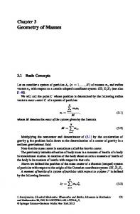
Fig. 2. A scheme for Brazilian disk under diametrical compression (a), and cross sections showing straight notch (b) and chevron notch (c)
D diameter of the specimen; S support span; a notch length; r
S=D=3:33; and, P load at failure. 2.2 Mixed Mode I±II A notched Brazilian disk under diametrical compression (Fig. 2), and semicircular specimens (Fig. 3) under three point bending were used for Mode-II and mixed Mode I±II fracture toughness calculation. The formulation for fracture toughness calculation for both types of specimens is explained below. Straight-notched Brazilian Disk Specimens The mathematical expression proposed by Atkinson et al. (1982) for fracture toughness calculation is used in this study. The expression has the following form: p P a p NI ;
5 KI pRB p P a p NII ;
6 KII pRB where,
Specimen Geometry and Testing Method on Mixed Mode I±II Fracture Toughness
183
Fig. 3. A scheme for semicircular specimen
KI Mode-I stress intensity factor; KII Mode-II stress intensity factor; R radius of the Brazilian disk; B thickness of the disk; P compressive load at failure; a half crack length; and, NI and NII are non-dimensional coe½cients which depend on a=R and the orientation angle
b of the notch with the direction of loading. Atkinson et al. (1982) proposed the following expressions for NI and NII : � �2iÿ2 n X a Ti Aib ;
7 NI R i1 NII 2 sin 2b
n X i1
Si
� �2iÿ2 a Bib ; R
8
where, Ti ; Si numerical constants; and, Aib ; Bib angular constants. For the half crack to radius ratio
a=R U 0:3, Atkinson et al. (1982) proposed the following approximation for NI and NII in terms of the crack inclination angle
184
K. Khan and N. A. Al-Shayea
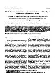
Fig. 4. Variation of NI and NII for notched Brazilian disk
with respect to the loading direction, b: NI 1 ÿ 4 sin 2 b 4 sin 2 b
1 ÿ 4 cos 2 b "
� �2 a ; R
� �2 # a sin 2b: NII 2
8 cos b ÿ 5 R 2
9
10
The variation of NI and NII obtained from Eqs. (7) and (8) is shown in Fig. 4. As a comparison, results from Eqs. (9) and (10) with
a=R 0:3 are also shown. For b 0 (i.e. pure Mode-I), Shetty and Rosen®eld (1985) derived the following third order polynomial for NI by ®tting the numerical results of Atkinson et al. (1982): NI 0:99 0:141
a=R 0:863
a=R 2 0:886
a=R 3 :
11
Specimen Geometry and Testing Method on Mixed Mode I±II Fracture Toughness
185
Chevron-notched Brazilian Disk Specimens Equations (5) and (6) for the stress intensity factor in mixed Mode I±II fracture toughness studies were originally developed for straight notched Brazilian disk geometry (Fig. 2b). When the crack or opening in the specimen is a chevron type (Fig. 2c), the formulation remains valid but before the specimens are tested in mixed Mode I±II, it is recommended that they be precracked under Mode-I to achieve a sharp crack tip (Shetty and Rosen®eld, 1985). Keeping in mind that the purpose of precracking is only to achieve a sharp crack tip, and recognizing the di½culty of precracking, it was decided to use the chevron notch without precracking. The mathematical formulation described above for the stress intensity calculation is also used for the specimens with a chevron notch. It is not expected that the di¨erence in results will be considerable. Moreover, in order to compare the results with the straight notched specimens, the crack to radius ratio
a0 =R, Fig. 2c, for the chevron notched specimens was chosen as 0.3. Semicircular Specimen Semicircular specimens have been used for a number of Mode-I fracture toughness determination tests, and the results have been found comparable to other techniques (Lim et al., 1994a). Originally, this arrangement was used for the Mode-I fracture toughness studies, and lately also for mixed Mode I±II fracture toughness studies using di¨erent crack orientations. Depending on the crack length, its orientation with respect to the loading direction, and the distance between the supports, a variety of mixed-mode failure patterns can be achieved. For pure Mode-I, the crack is aligned parallel to the direction of the load and lies below the loading point. However, for pure Mode-II, a slight misalignment of the specimen and/or crack orientation may induce a component of Mode-I loading and pure Mode-II cannot be achieved. Fracture toughness results under mixed Mode I±II for straight notched semicircular and Brazilian disk specimens are compared here to ascertain whether or not semicircular specimens can be an alternative to the Brazilian disk specimens. Lim et al. (1994b) also conducted some mixed Mode I±II tests using this specimen geometry. The stress intensity factor is determined by the following expressions: p
12 KI s0 paYI for b V 0 p
13 KII s0 paYII for b > 0 where, b crack orientation with respect to loading direction; KI , KII Mode-I and Mode-II stress intensity factors, respectively; a notch or crack length; s0 P=2RB P failure load;
186
K. Khan and N. A. Al-Shayea
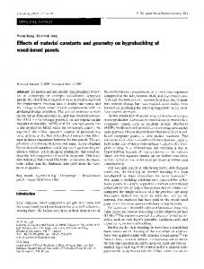
Fig. 5. Normalized stress intensity factors for a semicircular specimen
R specimen radius; B specimen thickness; and, YI ; YII normalized stress intensity factors for Mode-I and Mode-II, respectively. The variation of YI and YII for the range of notch lengths and inclination angles for a half span to radius ratio
S=R of 0.5 was reported by Lim et al. (1994b). According to them, pure Mode-II loading cannot be obtained without b exceeding 60� for
a=R < 0:34. However, YI and YII become very sensitive at large
a=R values. Consequently, the shortest possible
a=R should be used. Pure Mode-I can also be achieved by using a YI value corresponding to b 0. For comparison with the notched Brazilian disk results, a crack to radius
a=R ratio of 0.3 was used in this study. Also, the span to diameter
2S=D ratio was restricted by the size of the crack extension measurement assembly and was chosen as 0.8. Numerical results obtained by Lim et al. (1993) have been plotted as a function of b in degrees in Fig. 5 and can be approximated by the following polynomials which are used in this study: YI 4:832ÿ0:0053bÿ0:0015b 2 1:183�10ÿ5 b 3
with average R 2 0:99;
14
YII 0:0595bÿ0:00066b 2
with average R 2 0:99:
15 Tensile Strength
Tensile strength, st , was determined for the uncracked Brazilian disk using the following expression: st 2P=p;
16
Specimen Geometry and Testing Method on Mixed Mode I±II Fracture Toughness
187
Fig. 6. Loading setup for fracture toughness testing
where, P load at failure; B thickness of disk; and, D diameter of disk. 3. Experimental Program To investigate the e¨ect of notch length and type, specimen diameter, and thickness on fracture toughness, notched Brazilian disks, Straight Edge Cracked Round Bar Bend (SECRBB) and notched semicircular specimens were tested. The Brazilian disks were tested under diametrical compression; while the SECRBB and semicircular specimens were tested under three point bending. The loading setup used is schematically shown in Fig. 6 with a semi-circular specimen being mounted. 3.1 Testing Equipment A strain-controlled loading frame having a capacity of 100 kN was used for the load application, Fig. 6. Initially, circular rod specimens were tested under three point bending over a range of strain rates varying from 0.005 mm/min to 0.1 mm/min. Based on these results, a strain rate of 0.08 mm/min was chosen for the rest of the experiments. The applied load, load point displacement, and crack opening were acquired using a computerized data logger.
188
K. Khan and N. A. Al-Shayea
3.2 Specimen Preparation Rock blocks were collected from a limestone rock formation outcropping in the Central Province of Saudi Arabia. Preliminary studies showed that this limestone rock is a homogenous, muddy limestone, yellowish light-brown in color, very tight and lacks any pores visible under a polarizing microscope, and therefore it has a negligible porosity. It has a dry density of 2.586 gm/cm 3 , a speci®c gravity of 2.737, a void ratio of 0.055, a porosity of 5.4%, and a uniaxial uncon®ned compressive strength of 105 MPa. Cores were obtained from the rock blocks. Cores were 84 mm and 98 mm in diameter for the disk specimens, and 24 mm for the SECRBB specimens. The cores of 84 mm and 98 mm were sliced into circular disks of various thicknesses, using a high-speed diamond plated rotary saw. The sliced disks were sanded to ensure uniform thickness. For the semicircular specimens, the sliced disks were cut along the diameter into two equal halves. A notch was made in the center of the disk and semicircular specimens, and at the midspan of the circular rod specimens using a wire saw, with a wire thickness of 0.25 mm. For the SECRBB specimens, notch making was very simple and required only pressing of the specimen against the rotating diamond-impregnated wire. The depth of the cut was precisely controlled by a moving platform on which specimen was mounted. For the disk specimens, a hole was initially drilled at the center using a 3-mm drilling bit in a lathe. The bit was made to penetrate the rotating disk to the mid-thickness of the specimen, then the disk was reversed and the hole was completed. The wire of the saw was passed through the drilled hole and a notch of any length was machined in the disk in the same way as for the rod specimens. For the semicircular specimens, a radial line was marked at the required orientation with respect to the loading direction. A notch of any required length was then made along this marked line. It was di½cult to machine a crack at an angle greater than 60� for the semicircular specimens. Some of the notched specimens are shown in Fig. 7. The chevron notches were made using a slow speed circular saw with a disk of 80 mm (A3 inch) diameter and 1.8 mm thickness. The rock disks were ®rst marked on both sides along the diameter of the disk to show the two extreme points up to which the saw could cut, Fig. 2c. The length of the extreme point on each side from the center along the diameter of the disk was 30 mm. The marked Brazilian disk was pressed against the rotating circular saw until the saw reached the two marked extreme points. The disk was removed and turned, then the same procedure was repeated from the other side of the disk. This made a central opening 2a0 of about 29 mm. During the notch-making process, the disks were held manually against the saw, making it di½cult to obtain precise dimensions and crack geometry. 3.3 Testing The experimental program is summarized in Table 1. It consists of various sets of tests to study e¨ects of di¨erent parameters on Mode-I and mixed Mode I±II fracture toughness. Indirect tensile strength was also determined.
Specimen Geometry and Testing Method on Mixed Mode I±II Fracture Toughness
(a)
(b)
(c)
Fig. 7a±c. Notched specimens. a SECRBB, b Brazilian disk, and c semicircular specimens
189
190
K. Khan and N. A. Al-Shayea Table 1. Summary of experimental work
Test type
Variable
Specimen type
Specimen description
Mode-I fracture toughness
Strain rate (0.005, 0.01, 0.1 mm/min)
SECRBB
D 24 mm, a 7 mm, a=D 0:3
Notch length
a
Straight-notched Brazilian disk 2a 10 to 50 mm a=R 0:1 to 0.5
D 98 mm, B 22 mm
SECRBB a 3 to 13.5 mm a=D 0:13 to 0.50
D 24 mm, S 108 mm
Thickness of specimen
B
Straight-notched
11 to 25 mm
Brazilian disk
D 98 mm, 2a 30 mm, a=R 0:3
Size of specimen
D 98 and 84 mm
Straight-notched Brazilian disk
B 22 mm and 20 mm a=R 0:3, B=D 0:23
Size of specimen
D 98 and 84 mm
Straight-notched Brazilian disk
a=R 0:3, b 0 to 75� D 98 and 84 mm, a=R 0:3, B=D 0:23
Notch type (straight & chevron)
Brazilian disk
D 98 mm, a=R 0:3, B 22 mm, b 0 to 75�
Specimen type
Brazilian disk
D 98 mm, a=R 0:3, B 22 mm, b 0 to 75�
Semicircular
D 98 mm, B 22 mm, a=R 0:3 S 80 mm, b 0 to 60�
Uncracked Brazilian disk
D 98 mm, B 22 mm
Mode I±II fracture toughness
Tensile strength
Ð
Mode-I The e¨ect of the strain rate was studied using circular rod specimens of 24 mm diameter, tested under three point bending. A notch depth of 7 mm (i.e., a=D 0:3) was maintained for all specimens, which were tested with strain rates of 0.005, 0.01, 0.1 mm/min. The e¨ect of notch length on Mode-I fracture toughness was investigated using centrally notched Brazilian disks in diametrical compression, and notched SECRBB specimens under three point bending. The disks used for this purpose were 98 mm in diameter and about 22 mm in thickness, B. Straight notches of length 10 to 50 mm (i.e. a=R 0:1 to 0.5) were used. For the SECRBB specimens, the diameter was kept constant at 24 mm, the span, S, was also kept constant at 108 mm, and crack length was varied from 3 to 13.5 mm (i.e., a=D 0:13 to 0.56).
Specimen Geometry and Testing Method on Mixed Mode I±II Fracture Toughness
191
Brazilian disks, 98 mm in diameter with a central straight notch of 30 mm (i.e. a=R 0:3), were employed to investigate the e¨ect of specimen thickness, B, on Mode-I fracture toughness. Specimens with thicknesses ranging between 11 and 25 mm were used in this investigation. The e¨ect of specimen size on Mode-I fracture toughness was investigated by conducting tests on two Brazilian disk specimens of 98 mm and 84 mm in diameter with a thickness of 22 mm and 20 mm, respectively, and with a crack length to radius ratio
a=R of 0.3 for both specimens. Two specimens of each size were tested. Mixed Mode I±II The mixed Mode I±II fracture toughness study was made using Brazilian disks as well as semicircular specimens. The Brazilian disks were tested with crack orientations ranging between 0 to 75� . The semicircular specimens were tested with notch orientations between 0 to 60� . A notch to radius ratio
a=R of 0.3 was used for both types of specimens. The e¨ect of specimen size on mixed Mode I±II fracture toughness was investigated by conducting diametrical compression tests on centrally straight notched Brazilian disks, with a diameter of 98 mm and 84 mm. The crack to radius
a=R ratio and thickness to diameter
B=D ratio were chosen as 0.3 and 0.23, respectively. Straight-notched Brazilian disks were also used to study the e¨ect of crack size on mixed Mode I±II fracture toughness. The diameter and thickness (D and B) of the disks were 84 and 19 mm, respectively. The two normalized crack sizes (i.e., a=R) used in this investigation were 0.3 and 0.4. The e¨ect of the notch type was investigated using Brazilian disks with straight and chevron notches. The specimens used had
a=R ratio of 0.3, a diameter of 98 mm, and a thickness of 22 mm. For the semicircular specimens, notched specimens were centrally loaded using a three point loading arrangement. Semicircular specimens with 98 mm diameter and 22 mm thickness were chosen for this purpose. For comparison purposes, the thickness, diameter and crack length were the same for both types of specimens. The normalized crack ratio
a=R was taken to be 0.3. The semicircular specimens were tested under a three point bend loading con®guration with a span of 80 mm (i.e., a span to radius ratio
S=R of 0.8, Fig. 3). Any other span ratio was restricted by the size of both the specimen and the crack extensometer attached to the specimen to measure the crack extension during testing. The specimens were tested with a crack inclination with respect to the loading direction varying from 0� to 60� . Tensile Strength Tensile strength was determined using an uncracked Brazilian disk under diametrical compression. This test is the most widely used to determine the tensile
192
K. Khan and N. A. Al-Shayea
strength of rock materials (Andreev, 1995). Three disks were tested with a diameter of 98 mm and a thickness of 22 mm. 4. Results and Discussions 4.1 Tensile Strength The value of tensile strength, st , ranged between 2.13 and 2.39 MPa with an average value of 2.31 MPa. 4.2 Mode-I Results E¨ect of Loading Rate The fracture toughness results for di¨erent loading rates were found using Eq. (3). Figure 8 shows the variation of Mode-I fracture toughness as a function of the strain rate, which was found to range between 0.36 and 0.42 MPa m 1=2 . There is no signi®cant variation in the fracture toughness value for the strain rates used in this study. As a comparison, Haber®eld and Johnston (1990) and Lim et al. (1994b) studied the Mode-I fracture toughness variation of a saturated soft rock over a range of strain rates (i.e., 0.05±1.00 mm/min). They concluded that, at low strain rates, the fracture toughness variation was negligible. However, an increase in the fracture toughness value was observed at a higher strain level (i.e., 0.1±1.0 mm/min). This increase in fracture toughness at higher strain rates was attributed to the development of negative pore water pressure at the crack tip of water saturated samples caused by the high tensile stresses. In contrast, the rock material used in this study was dry and, consequently, an increase in fracture toughness at high strain rates was not expected. Accordingly, a strain rate of 0.08 mm/min was used for the rest of the experimental work in this study.
Fig. 8. E¨ect of loading rate on Mode-I fracture toughness
Specimen Geometry and Testing Method on Mixed Mode I±II Fracture Toughness
193
Fig. 9. E¨ect on notch length on Mode-I fracture toughness
E¨ect of Notch Length The fracture toughness with various notch lengths was calculated using Eqs. (5) and (11) for the Brazilian disks and Eq. (3) for the SECRBB specimens, and the results plotted in Fig. 9. The fracture toughness of the SECRBB and the notched Brazilian disk specimens as a function of the crack length are ®tted by a second degree polynomial having the following forms: � � � �2 a a ;
17 ÿ 0:811
KIC Brazilian disk 0:333 0:556 R R � � � �2 a a :
18
KIC SECRBB 0:459 0:594 ÿ 0:896 D D The results show an initial increase in the fracture toughness value up to a normalized crack length (a=R or a=D) of about 0.35, beyond which it starts to decrease. Accordingly, a value of 0.3 for
a=R or
a=D was used for the rest of this investigation. To investigate the validity of Eq. (1) for rocks,
KIC =st 2 and a=
KIC =st 2 were plotted versus the crack length
a for the SECRBB, the Brazilian disk, and the other specimens, Figs. 10a and b. As the crack length increases, a=
KIC =st 2 increases, but only to a value of about 0.8 for Brazilian disk with
a=R 0:5. Also,
KIC =st 2 and a=
KIC =st 2 were plotted versus the ligament length
W ÿ a, where W R for the semicircular and Brazilian disk and D for the SECRBB specimens, Figs. 10c and d. As the ligament length increases,
W ÿ a=
KIC =st 2 increases, but only to a value of about 1.7 for the Brazilian disk with
a=R 0:1. Notice that the ligament length increases with a decrease in the crack length. Furthermore, Fig. 10e shows that a=
KIC =st 2 is not even a constant, but rather a function of many parameters; including normalized crack
194
K. Khan and N. A. Al-Shayea
mm
Fig. 10. Criteria for determining specimen dimensions
Specimen Geometry and Testing Method on Mixed Mode I±II Fracture Toughness
195
Fig. 11. Fracture process zone (FPZ) for typical rock
length (a=R or a=D), specimen type (Brazilian disk, SECRBB, or semicircular), and notch type (straight or chevron). Based on the linear elastic fracture mechanics (LEFM) theory, the valid Mode-I fracture toughness value can be obtained only if the fracture process zone (FPZ) is small (i.e. a few percent) with respect to the overall dimensions of the specimens. Since limestone rocks behave as a brittle material, the FPZ is the nonlinear process zone caused by the initiation of the microcracks in the immediate vicinity of the crack tip, Fig. 11. Notch length is related to the ligament length which, in turn, hosts the FPZ. Singh and Pathan (1988) studied the fracture toughness behavior of ®ve di¨erent rocks using disks under diametrical compression load. The minimum notch lengths used for Ry®eld sandstone, siltstone, basalt, granite and coal were approximately 2.5, 4, 2, 2, and 3 mm, respectively. No decrease in fracture toughness was observed even with such a small crack length. This led them to conclude that the fracture toughness of those rocks was independent of the notch length. In contrast, Lubtz et al. (1987) used wedge-loaded, double cantilever beam specimens and came up with a process zone of approximately 40 and 90 mm for charcoal granite and Rockville granite, respectively. On the other hand, Laqueche et al. (1986) also used double cantilever beam specimens for the Mode-I fracture toughness of slate and reported almost no variation in the fracture toughness over the normalized notch length of 0.2 to 0.6. It is important to note that tensile loads were used for the double cantilever beam con®guration in the work conducted by Laqueche et al. (1986), whereas
196
K. Khan and N. A. Al-Shayea
for Singh and Pathan (1988), and in this work, compressive loads were used. According to Thiercelin and Roegiers (1986), it is likely that the application of compressive loads tends to induce non-singular compressive stresses normal to the crack face which result in a smaller process zone. On the other hand, non-singular tensile stresses will be created normal to the crack face in the case of double cantilever specimens. Therefore, it is more likely for the process zone to be enlarged in the case of tensile loads. Based on the above discussion, it can be concluded that Eq. (1) for the size of the FPZ, originally developed for ductile materials (i.e., metals), may not be representative of the actual process zone size for brittle materials (i.e. rocks) and the required notch length can be quite small. Similar remarks have also been made by Lim et al. (1994a) regarding the applicability of Eq. (1) for rocks. Moreover, it is believed that the dependence of Mode-I fracture toughness on the crack size may be material dependent rather than testing-technique dependent. E¨ect of Specimen Thickness The fracture toughness was calculated for various specimen thicknesses, using Eqs. (5) and (11), and the results plotted in Fig. 12. The fracture toughness (ranging from 0.39 to 0.42 MPa m 1=2 ) over the range of specimen thickness does not show any signi®cant variation. Haber®eld and Johnston (1990) conducted a large number of tests, using rectangular beams under three-point bend loading, and reached a similar conclusion. Similar ®ndings have been reported by Schmidt and Lutz (1979) for westerly granite, Fowell and Chen (1990) for ®ne grained sandstone, Chong et al. (1987) for Colorado oil shale, Singh and Sun (1990) for Welsh limestone, Kobayashi et al. (1986) for Ogino tu¨, and Laqueche et al. (1986) for slate schist in a double cantilever beam loading con®guration. Although di¨erent testing techniques were used in these studies, a similar conclusion was obtained.
Fig. 12. E¨ect of specimen thickness on Mode-I fracture toughness for straight notched Brazilian disks
Specimen Geometry and Testing Method on Mixed Mode I±II Fracture Toughness
197
Schmidt and Lutz (1979) explained the e¨ect of specimen thickness on Mode-I fracture toughness, as the maximum principal stress is responsible for the crack tip yield zone. It follows that the crack tip yield zone is independent of the out-of-plane stress. This implies that the size of the crack tip yield zone is also independent of the thickness of the specimen. Based on the consideration of the FPZ at the crack tip, Fig. 11, the size of the critical fracture process zone
rmc given in Eq. (2) was found to be 9 mm for the 98 mm Brazilian disks with values of 0.42 MPa m 1=2 and 2.31 MPa for KIC and st , respectively. If the stress redistribution is taken into account, specimen thickness
B should be greater than or equal to 2rmc (Whittaker et al., 1992). This dictates a specimen thickness of around 18 mm. The thickness of the specimens is therefore recommended as 22±26 mm for such disks. E¨ect of Specimen Diameter The results of the tests made to investigate the e¨ect of specimen diameter on Mode-I fracture toughness were found using Eqs. (5), (6), (9), (10), and presented in Fig. 13. Fracture toughness values of 0.35 and 0.42 MPa m 1=2 were found for the 84 and 98 mm diameter disks, respectively. This means that there was an increase of about 20% in the fracture toughness when the diameter was increased by 17%. No consensus has so far been found in the literature regarding the variation of Mode-I fracture toughness with specimen diameter. Matsuki et al. (1988) reported a trend of increasing fracture toughness with increased specimen diameter, while the results by Barker (1977), Sun (1983), and Yi (1987) suggest that Mode-I fracture toughness is independent of the specimen diameter. In all these references, specimens other than the centrally notched Brazilian disk were used.
Fig. 13. E¨ect of specimen diameter on Mode-I fracture toughness
198
K. Khan and N. A. Al-Shayea
Fig. 14. E¨ect of specimen diameter on mixed Mode I±II fracture toughness for straight-notched Brazilian disks
E¨ect of Specimen Type From Fig. 9, the SECRBB specimens gave a higher value for Mode-I fracture toughness
KIC than the straight-notched Brazilian disk specimens. For a=R or a=D equals 0.3, the value of KIC was found to be 0.42 and 0.55 MPa m 1=2 from Brazilian disk and SECRBB specimens, respectively. The semicircular specimens gave even a much higher value of 0.68 MPa m 1=2 , using Eqs. (12) and (14). The
KIC Brazilian disk is only about 76% of
KIC SECRBB and 61% of
KIC semicircular .
4.3 Mixed Mode I±II Results E¨ect of Specimen Size The results of the e¨ect of specimen size were found using Eqs. (5), (6), (9), (10), and the fracture toughness variations for the two specimen sizes are shown in Fig. 14 in terms of KI and KII for various crack inclination angles, b. The values of the fracture toughness for the smaller and the larger disks are di¨erent. Pure Mode-I
KIC and pure Mode-II
KIIC values for the 84 mm diameter disks were 0.35 and 0.75 MPa m 1=2 , respectively, compared to the corresponding values of 0.42 and 0.92 MPa m 1=2 for the 98 mm disks. By increasing disk diameter from 84 mm to 98 mm, KIC increased by an amount of 20% and KIIC increased by about 30%. The ratio of pure Mode-II to pure Mode-I
KIIC =KIC was obtained as 2.14 and 2.19 for the 84 and 98 mm disks, respectively. Variations of normalized Mode-I
KI =KIC and Mode-II
KII =KIIC fracture toughness are shown in Fig. 15. The normalized fracture toughness for Mode-I and Mode-II for the two specimen sizes
Specimen Geometry and Testing Method on Mixed Mode I±II Fracture Toughness
199
Fig. 15. E¨ect of specimen diameter on normalized mixed Mode I±II fracture toughness for straightnotched Brazilian disks
are related to each other by the following equations: � � � � KI KI 1:15 with R 2 0:983; KIC
98 mm KIC
84 mm � � � � KII KII 1:09 with R 2 0:976: KIIC
98 mm KIIC
84 mm
19
20
This means that the normalized fracture toughness of the 98 mm disk is greater than that of the 84 mm disk by 15% and 9% for Mode-I and Mode-II, respectively. E¨ect of Notch Length Fracture toughness results for
a=R equal to 0.3 and 0.4 were calculated using Eqs. (5±8) and plotted in Fig. 16. The variation in the mixed Mode I±II fracture toughness is negligible, at least for the range of crack size used in this study. Pure Mode-I
KIC and pure Mode-II
KIIC values for a=R 0:4 were found to be 0.37 and 0.79 MPa m 1=2 , respectively, compared to corresponding values of 0.35 and 0.75 MPa m 1=2 for specimens with a=R 0:3. The results di¨er only by about 5%. The
KIIC =KIC ratio for both crack lengths is almost the same, and is equal to 2.14. The normalized Mode-I and Mode-II fracture toughness are shown in Fig. 17 for notch lengths
a=R of 0.3 and 0.4, and they are related by the following equations: � � � � KI KI 0:964 with R 2 0:976;
21 KIC
a=R0:3 KIC
a=R0:4 � � � � KII KII 1:062 with R 2 0:970:
22 KIIC
a=R0:3 KIIC
a=R0:4
200
K. Khan and N. A. Al-Shayea
Fig. 16. E¨ect of crack length on mixed Mode I±II fracture toughness for straight-notched Brazilian disks
Fig. 17. E¨ect of crack length on normalized mixed Mode I±II fracture toughness for straight-notched Brazilian disks
This indicates that the normalized Mode-I fracture toughness for
a=R equal to 0.3 is 4% less than that for
a=R equal to 0.4, but the normalized Mode-II fracture toughness for
a=R equal to 0.3 is 6% more than that for
a=R equal to 0.4. E¨ect of Notch Type Fracture toughness results for straight- and chevron-notched Brazilian disks were found using Eqs. (5), (6), (9), (10). Figure 18 shows the variations of the mixed
Specimen Geometry and Testing Method on Mixed Mode I±II Fracture Toughness
201
Fig. 18. Comparison of mixed Mode I±II fracture toughness for straight- and chevron-notched Brazilian disk specimens
Fig. 19. Normalized Mode-I and Mode-II fracture toughness for straight- and chevron-notched Brazilian disk specimens
mode fracture toughness for both types of notches over a range of inclination angles. The results for both notch types are in good agreement except for pure Mode-I. The fracture toughness values for pure Mode-I
KIC and Mode-II
KIIC for chevron notched specimens were 0.61 and 0.86 MPa m 1=2 , respectively. The corresponding values for the straight notch were 0.42 and 0.92 MPa m 1=2 . The ratio of pure Mode-II to pure Mode-I
KIIC =KIC was found to be 1.41 for the chevron notch, compared to a value of 2.19 for the straight notch. The normalized Mode-I and Mode-II fracture toughness results are presented in Fig. 19, with the
202
K. Khan and N. A. Al-Shayea
following relationships: � � � � KI KI 1:15 KIC chevron KIC straight � � � � KII KII 0:99 KIIC chevron KIIC straight
with R 2 0:94;
23
with R 2 0:95:
24
This means that the normalized Mode-I fracture toughness for the chevronnotched disk is 15% greater than that with the straight notch, but the normalized Mode-II is almost the same for both specimens. However, due to the fact that the straight notch was very sharp (0.25 mm) compared to a 1.8 mm thick chevron notch, and because crack boundaries and alignment of the crack along the diameter of the specimen were di½cult to control while machining a chevron notch, it was decided to use only the straight notch for the remaining samples used for the fracture toughness investigation. E¨ect of Specimen Type The fracture toughness results for semicircular specimens were calculated using Eqs. (12±15). A comparison of the mixed Mode I±II results for the semicircular and Brazilian disk specimens is shown in Fig. 20. The pure Mode-I fracture toughness
KIC for the semicircular specimens is about 0.68 MPa m 1=2 , compared to the average value of 0.42 MPa m 1=2 for Brazilian disk specimens with the same diameter. The pure Mode-II fracture toughness
KIIC value cannot be obtained from the existing results. Since the load at failure, and hence the fracture toughness, is dependent on the radius to span ratio (i.e. S=R) for semicircular specimens,
Fig. 20. Comparison of mixed Mode I±II fracture toughness for straight-notched Brazilian disk and semicircular specimens
Specimen Geometry and Testing Method on Mixed Mode I±II Fracture Toughness
203
this ratio has to be standardized to obtain a unique solution for this type of specimen geometry. For semicircular specimens with smaller crack lengths, pure Mode-II may be obtained at very large crack inclinations. However, crack machining becomes almost impossible for inclinations larger than 60� . On the other hand, for larger crack lengths which facilitate the obtainability of pure Mode-II at smaller crack inclination angles, the size of FPZ limits the applicability of LEFM. Therefore, it can be concluded that the results for the semicircular specimen geometry are not comparable to the notched Brazilian disk for mixed Mode I±II, even if other geometrical parameters are the same for both specimen types. However, for studying pure Mode-I fracture toughness, a semicircular specimen can be a good shape, provided that the
S=R ratio is correctly chosen. It has the advantage of requiring less materials. However, the above ®ndings encourage the use of the notched Brazilian disk geometry over semicircular specimens for studying mixed Mode I± II fracture toughness.
5. Conclusions The following conclusions are drawn from the experimental results obtained from testing limestone rock formation outcropping in the Central Province of Saudi Arabia. For the determination of tensile strength and fracture toughness, the Brazilian disk specimens were found to be most convenient. The disk is recommended to be about 22±26 mm thick, and 97±101 mm in diameter. A straight notch is much more convenient than chevron notch, especially when the combination of a drilling machine and a wire saw are used to make a very precise notch. The tensile strength was found to be 2.31 MPa. Loading rate, specimen thickness, and crack length were found to have no signi®cant e¨ect on fracture toughness. However, specimen diameter, crack type, and specimen type signi®cantly a¨ected the fracture toughness. Particularly ModeI fracture toughness was signi®cantly in¯uenced by these variables, while their e¨ects on Mode-II fracture toughness were not signi®cant. KIC and KIIC were found to increase from 0.35 and 0.75 MPa m 1=2 , respectively, for D 84 mm to 0.42 and 0.92 MPa m 1=2 , respectively, for D 98 mm. This means that when the diameter was increased by 17%, KIC increased by 20% and KIIC increased by 30%. The e¨ect of notch type is more pronounced on Mode-I fracture toughness. KIC and KIIC for the chevron-notched specimens were 0.61 and 0.86 MPa m 1=2 , respectively, compared to 0.42 and 0.92 MPa 1=2 for the straight-notched specimens. This means that KIC for the chevron-notched specimen was 45% greater than with the straight notch, but KIIC for the chevron-notched specimen was 7% smaller than with the straight notch. Fracture toughness values determined using di¨erent specimen geometries are not comparable. These values are signi®cantly in¯uenced by the support (S or 2S) span for the SECRBB and semicircular specimens. The support span needs to be
204
K. Khan and N. A. Al-Shayea
standardized for a valid comparison of results with those obtained for the Brazilian disk specimens. This requires further investigation to specify also the size of the sample and the crack length.
Nomenclature a a1 Aib a0 B Bib CCNBD CSTBD D FPZ KI KIC KII KIIC LEFM NI NII P R R2 rmc S 2S SECRBB Si SIF Smin Ti W Y0 YI YII r s0 st b
Notch length (half of the crack length for Brazilian disk) Maximum crack length for chevron notch Angular constant Minimum crack length for chevron notch Thickness of the specimen Angular constant Cracked chevron notched Brazilian disk Cracked straight through Brazilian disk Diameter of the specimen Fracture process zone Mode-I stress intensity factor Pure Mode-I stress intensity factor Mode-II stress intensity factor Pure Mode-II stress intensity factor Linear elastic fracture mechanics Normalized Mode-I stress intensity factor for notched Brazilian disk Normalized Mode-II stress intensity factor for notched Brazilian disk Load at failure Radius of the specimen Coe½cient of determination Size of the critical FPZ Support span for circular rod specimen Support span for semicircular specimen Straight edge cracked round bar bend Numerical constant Stress intensity factor Minimum strain energy density Numerical constant Equals D for SECRBB, and equals R for Brazilian disk Normalized stress intensity factor for circular rod specimen Normalized stress intensity factor for Mode-I for semicircular specimens Normalized stress intensity factor for Mode-II for semicircular specimens
S=D=3:33 P=2RB Tensile strength Crack inclination angle (degrees) with respect to the loading direction
Acknowledgements The authors acknowledge the support of King Fahd University of Petroleum and Minerals for providing computing and laboratory facilities. They also would like to acknowledge the support of Saudi-ARAMCO through the Research Institute, KFUPM. They are also grateful to Dr. Abdulraheem from the Petroleum Engineering Section, RI, and to Mr. Hasan Zakaria from the geotechnical laboratory, Civil Engineering Department.
Specimen Geometry and Testing Method on Mixed Mode I±II Fracture Toughness
205
References Andreev, G. E. (1995): Brittle failure of rock materials, test results and constitutive models. A. A. Balkema, Rotterdam, 149 pp. Atkinson, C., Smelser, R. E., Sanchez, J. (1982): Combined mode fracture via the cracked Brazilian disk. Int. J. Fracture 18, 279±291. Barker, L. M. (1977): A simpli®ed method for measuring plain-strain fracture toughness. Engng. Fract. Mech. 9, 361±369. Barton, C. C. (1982): Variables in fracture energy and toughness testing of rock. Proc., 23rd U.S. Symp. on Rock Mech., 145±157. Chong, K. P., Kuruppu, M. D., Kuszmaul, J. S. (1987): Fracture toughness determination of layered materials. Engng. Fract. Mech. 28, 55±65. Fowell, R. J., Chen, J. F. (1990): The third chevron notch rock fracture specimen ± the cracked chevron-notched Brazilian disk. Proc., 31st U.S. Symp. on Rock Mech., 295± 302. Haber®eld, C. M., Johnston, I. W. (1990): Determination of the fracture toughness of a saturated soft rock. Can. Geotechn. J. 27, 276±284. Kobayashi, R., Matsuki, N., Otsuka, N. (1986): Size e¨ect in the fracture toughness of Ogino tu¨. Int. J. Rock Mech. Min. Sci. Geomech. Abstr. 23(1), 13±18. Laqueche, H., Rousseau, A., Valentin, G. (1986): Crack propagation under Mode-I and II loading in slate schist. Int. J. Rock Mech. Min. Sci. Geomech. Abstr. 23(5), 347± 354. Lim, I. L., Johnston, I. W., Choi, S. K. (1993): Stress intensity factors for semicircular specimens under three-point bending. Engng. Fract. Mech. 44(3), 363±382. Lim, I. L., Johnston, I. W., Choi, S. K., Boland, J. N. (1994a): Fracture testing of a soft rock with semicircular specimens under three point bending ± Part 1. Int. J. Rock Mech. Min. Sci. Geomech. Abstr. 31(3), 185±197. Lim, I. L., Johnston, I. W., Choi, S. K., Boland, J. N. (1994b): Fracture testing of a soft rock with semicircular specimens under three point bending ± Part 2. Mixed mode. Int. J. Rock Mech. Min. Sci. Geomech. Abstr. 31(3), 199±212. Lubtz, J. F., Shah, S. P., Dowding, C. H. (1987): The fracture process zone in granites: evidence and e¨ects. Int. J. Rock Mech. Min. Sci. Geomech. Abstr. 24, 235±246. Matsuki, K., Nozuyama, Y., Takahashi, H. (1988): Size e¨ect in fracture testing of rocks using a boring core. Proc., Spring Meeting, Mining and Metallurgical Institute, Japan, 193±194. Ouchterlony, F. (1981): Extension of compliance and stress intensity formulas for the single edge cracked round bar in bending. ASTM STP 745, 237±256. Schmidt, R. A. (1976): Fracture-toughness testing of limestone. Exp. Mech. 16, 161±167. Schmidt, R. A., Lutz, T. J. (1979): KIC and JIC of westerly granite ± e¨ects of thickness and in-plane dimensions. ASTM STP 678, 166±182. Shetty, D. K., Rosen®eld, A. R. (1985): Fracture toughness of ceramics measured by a chevron-notch diametral-compression test. J. Am. Ceram. Soc. 65(11), 566±572. Singh, R. N., Pathan, A. G. (1988): Fracture toughness of some British rocks by diametral compression of disks. Min. Sci. Tech. 6, 179±190. Singh, R. N., Sun, G. X. (1990): A numerical and experimental investigation for determining fracture toughness of Welsh limestone. Min. Sci. Tech. 10, 61±70.
206
K. Khan and N. A. Al-Shayea: Specimen Geometry
Sun, Z. Q. (1983): Fracture mechanics and tribology of rocks and rock joints. PhD Thesis; Lulea University, Sweden. Thiercelin, M., Roegiers, J. C. (1986): Toughness determination with the modi®ed ring test. Proc., 27th U.S. Symp. on Rock Mech., 615±622. Whittaker, B. N., Singh, R. N., Sun, G. (1992): Rock fracture mechanics: principles, design and applications. Developments in geotechnical engineering. Elsevier, Amsterdam. Yi, X. P. (1987): Fracture toughness and crack growth in short rod specimens of rocks. Licentia Thesis; Division of Rock Mechanics, Lulea University, Sweden. Authors' address: Dr. Naser A. Al-Shayea, Civil Engineering Department, KFUPM, P.O. Box 368, Dhahran 31261, Saudi Arabia.