Hindawi Publishing Corporation Advances in Condensed Matter Physics Volume 2012, Article ID 420619, 7 pages doi:10.1155/2012/420619
Research Article Effect of Synthesis Temperature on the Growth Iron-Filled Carbon Nanotubes as Evidenced by Structural, Micro-Raman, and Thermogravimetric Analyses M. S. Shamsudin,1, 2 N. A. Asli,1, 2 S. Abdullah,1, 2 S. Y. S. Yahya,1, 2 and M. Rusop1, 3 1 Centre
of Nanoscience and Nanotechnology (NANO-SciTech Centre), Institute of Science, Universiti Teknologi MARA, 40450 Shah Alam, Malaysia 2 School of Physics and Material Studies, Faculty of Applied Sciences, Universiti Teknologi MARA, 40450 Shah Alam, Malaysia 3 NANO-ElecTronic Centre, Faculty of Electrical Engineering, Universiti Teknologi MARA, 40450 Shah Alam, Malaysia Correspondence should be addressed to M. S. Shamsudin,
[email protected] Received 6 March 2012; Revised 24 April 2012; Accepted 30 April 2012 Academic Editor: Mohindar S. Seehra Copyright © 2012 M. S. Shamsudin et al. This is an open access article distributed under the Creative Commons Attribution License, which permits unrestricted use, distribution, and reproduction in any medium, provided the original work is properly cited. Tubular structure and well dense of aligned carbon nanotubes (CNTs) were formulated using two-stage catalytic chemical vapor deposition apparatus. In this experiment, aligned CNT was synthesized in the range of 700–900◦ C temperatures with increment rate of 50◦ C per sample. The aligned CNT properties were investigated via field emission scanning electron microscope, microRaman spectrometer and thermogravimetric analyzer. The experimental results showed that aligned CNT properties were highly dependent on synthesis temperature changes. The optimum temperature of higher crystallinity was observed at 800◦ C synthesis temperature. However, the highest yield of nanotubes (∼99.99%) was obtained at 900◦ C synthesis temperature. Aligned CNT orientation was in a parallel form and packed together in orderly manner. The behaviors of aligned CNT will be discussed in detail in this paper.
1. Introduction Nearly twenty years after their discovery, CNT holds excessive potential for use in functional devices due to unusual properties. It could be used as a starting material for field emission display [1, 2], supercapacitor electrodes [3, 4], electron field emitter [5, 6], hybrid fuel cell [7, 8], and chemical sensor [9, 10]. A thousand of patents and publications describe CNT as a tubular structure covalently bonded carbon atoms, having large aspect ratio (diameter of few nanometer order but length in micrometers). Many methods for synthesizing CNT have been developed, in various conditions, including laser evaporation [11, 12], carbon arc [13, 14], and chemical vapor deposition (CVD) [15, 16]. Among these methods, CVD method emerged as a cost-effective technique [17, 18] because of its benefits: ease to scale up and versatility in the
experimental set-up. Moreover, in view of the CNT demand, hopefully with the same technique, it can be transferred to a big reactor for large-scale industry. As the CNT researchers, it is advisable to choose a hydrocarbon precursor (starting material) from unconventional, new, and waste ones, such as [19–21] botanical-hydrocarbon-based CNT. It is found that fossil-based CNT-production technology (i.e., methane, ethanol, benzene, and xylene) would not be sustainable due to unstable supply of oil resources [22–24]. The use of natural renewable carbon sources support the part of 12 principles of green chemistry formulated by the United States Environmental Protection Agency [25]. Furthermore, this paper deals with the production of aligned CNT using two-stage catalytic CVD. In this experiment, growth-control aspect such as effect of synthesis temperature is depicted. The objectives are to show that
2
Advances in Condensed Matter Physics
(a)
(b)
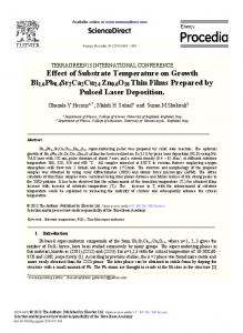
Figure 1: (a) Conceptual drawing of two-stage catalytic CVD and (b) optical photograph of CNT inside the bottle.
this method provides information on unanswered questions about growth mechanism and existing challenges to obtain well-aligned nanotubes structure. In addition, the aligned CNT has been characterized by using a number of analytical characterization techniques. Therefore, field emission scanning electron microscopy (FESEM), micro-Raman, and thermogravimetric (TG) analyses become very useful techniques to explain the behavior of aligned CNT. However, the aligned CNT in powder form (without deposited on any substrates) synthesized by two-stage catalytic CVD has not yet been reported.
2. Experimental and Materials Camphor oil (99.95% purity, SAFC) and ferrocene (99.95% purity, Sigma Aldrich) were used without any pretreatment process. In each experiment, a detailed description of processing synthesis temperature (700 to 900◦ C increment of 50◦ C at second furnace) by using the two-stage catalytic CVD apparatus has been illustrated. The experimental set up that used to produce aligned CNT using two-stage catalytic CVD is shown in Figure 1(a). Two-stage catalytic CVD is a one of lab-scale equipments and compatible for feasibility studies. The catalyst (ferrocene) and carbon feedstock (camphor oil) were placed in different alumina boats same as in previous experimental experience [26]. Both of them were located side by side along quartz tube at the centre of the first furnace. Then, the quartz tube was heated for 1 hour under N2 ambient with flow rate of 10 standard cubic centimetres (sccm) as a carrier gas to flush out any presence of other gases. The aligned CNT was found to be deposited in the innertube of second furnace. The furnace was cooled to room temperature and sample was collected as shown in Figure 1(b) for characterization process [27]. The aligned CNT was characterized by field emission scanning electron microscopy (FESEM, ZEISS 77 SUPRA 40VP) at 5 kV electron high tension (EHT) without gold or platinum coating, micro-Raman spectrometer (μ-Raman, Horiba Jobin Yvon 79 DU420A-OE-325) at room temperature using Ar+ ion laser at 514.32 nm wavelength source and 20 mW power. Thermogravimetric analyzer (TGA, PE Pyris 1 TGA Thermo Balance) was used for further characterization of the synthesized aligned CNT with heating rate of 20◦ C/min up to 1000◦ C under flow of oxygen gas.
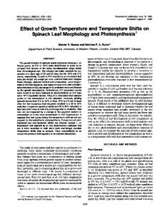
3. Results and Discussion 3.1. Surface Morphology. In this experimental condition, the construction of two-stage catalytic CVD apparatus generates new idea and alternative strategy to synthesize high-dense and tubular shape of nanotubes. Some of the important issues in aligned CNT relate to growth control including better control of sizes, structures, properties, and performances. It is hard to understand how CNT formed. To illustrate this aspect, the FESEM micrograph shows a clear view of the overall structural morphology and growth of the synthesized aligned CNT as in Figure 2. The correspondence synthesis temperature changes with the characteristics of the CNT were observed [28]. Based on experimental experience, by changing the magnitude of synthesis temperature, the structure of hydrocarbonbased material gradually changes from spherical consisted of grapheme shell and amorphous carbon (a-C) [29, 30] to tubular [31] structure under certain condition. By increasing the synthesis temperature, the geometry and size of nanotubes were affected in CNT nucleation-growth process. Towards certain extend, the hydrocarbon source cannot produce aligned CNT without catalyst [26, 32]. Therefore, in line with previous study reported by Groudeva-Zotova et al. [33], iron (Fe) clusters produced by decomposition of ferrocene at 180◦ C (confirmed by a thermogram evidenced by TGA as in Figure 3) was at the sublimation zone to activate catalytic activity for the growth of aligned CNT. The diameter distribution of aligned CNT was confirmed by the size of catalyst as reported by Chee and Sharma [34]. Probably the Fe clusters obtained at the different synthesis temperatures might vary in shape as well as in size. In the Figures 2(a) and 2(b), the samples contain small amount of carbonaceous by-product such as, a-C surrounding aligned CNT that affect tubular diameter distribution. A twisted nanotubes structure was attained exactly from fewer Fe clusters that were available for aligning process due to imperfect catalytic effect. This evidence also explains the characteristics anisotropic properties of Fe clusters where the bigger Fe clusters produced cannot fully decompose in the reaction zone to enhance the growth of aligned CNT with small diameter. At the higher temperature, the possibilities of aligned CNT growth were high. It was showed in the Figures 2(c), 2(d), and 2(e) that high-dense aligned CNT has been successfully synthesized at the higher synthesis
Advances in Condensed Matter Physics
10 µm
EHT = 5 kV WD = 9.1 mm
Signal A = InLens Mag = 1 kx
3
10 µm
Date: 2 Aug 2010 Time: 11:29:47
EHT = 5 kV WD = 9.2 mm
(a)
10 µm
EHT = 5 kV WD = 9.1 mm
Signal A = InLens Mag = 1 kx
Date: 2 Aug 2010 Time: 11:25:42
(b)
Signal A = InLens Mag = 1 kx
10 µm
Date: 2 Aug 2010 Time: 11:50:15
EHT = 5 kV WD = 6.1 mm
(c)
Signal A = InLens Mag = 1 kx
Date: 9 Aug 2010 Time: 15:13:14
(d)
10 µm
EHT = 5 kV
WD = 6 mm
Signal A = InLens Mag = 1 kx
Date: 9 Aug 2010 Time: 16:11:37
(e)
Figure 2: FESEM micrographs of aligned CNT at different synthesis time (a) 700, (b) 750, (c) 800, (d) 850, and (e) 900◦ C.
temperature from 800 to 900◦ C. The temperature at 800◦ C can be declared as a critical synthesis temperature due to: (i) Fe clusters become energetically stable, (ii) Fe clusters reach some critical size which related to the diameter of the nanotube, and (iii) Fe clusters may influence the CNT growth in one direction. Most interestingly, the hydrocarbon source
and ferrocene may all decompose at higher temperature and have high possibility to grow self-oriented aligned CNT in the core of quartz tubing. Apart from the growth control described above, aligned CNT was produced when ferrocene fully decomposed to produce smaller size of Fe clusters compared to the lower synthesis temperatures. So,
4
Advances in Condensed Matter Physics RBM
100
TM 1345 cm −1 1573 cm −1
90 80 Intensity (counts/s)
750◦ C
70 Weight (%)
700◦ C
60 50 40 30
800◦ C 850◦ C 900◦ C
20 10
0
500
0 0
20 40 60 80 100 120 140 160 180 200 220 240
1000 1500 Raman shift (cm−1 )
Temperature (◦ C)
(a) 700◦ C
Intensity (counts/s)
Camphor oil
Figure 3: TG analysis of camphor oil.
the fine Fe clusters will activate catalytic activity during this process. In this scenario, the best temperature for growth of aligned CNT was found at 800◦ C as optimized for camphorgrown-aligned CNT due to its perfect tubular structure for our system of two-stage catalytic CVD. On top of that, the synthesis temperature does play important roles in the growth of aligned CNT.
100
750◦ C 800◦ C 850◦ C 900◦ C 150
200
250 300 350 400 Raman shift (cm−1 )
450
500
(b)
Figure 4: (a) Micro-Raman analysis of aligned CNT at different synthesis temperature and (b) inset of micro-Raman spectra for RBM analysis.
0.75 0.7 Intensity (counts/s)
3.2. Micro-Raman Analysis. From micro-Raman results, the micro-Raman spectra of the carbon nanostructure at different synthesis temperature have been shown in Figure 4(a). First-harmonic micro-Raman spectra of the samples were measured in the range from 100 to 2500 cm−1 . The active mode of micro-Raman analysis is dependent on the synthesis temperature. Since the first harmonic micro-Raman shift was observed, active modes can be (i) graphitic feature (Gband) occurs at 1573 cm−1 , whereas (ii) disorder-induced feature (D-band) appears at 1345 cm−1 [35]. From the Figure 4(a), the D-band and G-band peaks were consistent for all samples without any significant change of the line position. A classical rule respective intensity ratio of D and G peaks (ID /IG ) has been introduced by Tuinstra’s group [36] which involves quality of nanotubes. They suggested the lower ID /IG (close to zero) corresponds for better degree of graphitization. The ID /IG ratios for 700, 750, 800, 850, and 900◦ C synthesized aligned CNT are 0.7178, 0.6872, 0.5239, 0.5571, and 0.5694, respectively. The higher ID /IG value leads to the presence of (i) structural and lattice defect and (ii) by-product carbon material, such as, a-C and nonuniform nanotubes. To summarize, these observations of TuinstraKoenig relation [36] as in Figure 5 reveal that the synthesized aligned CNT optimized at 800◦ C synthesis temperature. The representative spectra of the radial breathing mode (RBM) region are shown in Figure 4(b) (inset of Figure 4(a)). A faint peak ωRBM (cm−1 ) between 100 and 500 cm−1 can be deconvoluted to the RBM. This agrees very well when the spectra are excited with the monochromatic laser source
2000
ID /IG = 0.7178 ID /IG = 0.6872
0.65 0.6
ID /IG = 0.5571 ID /IG = 0.5694
0.55 0.5 650
ID /IG = 0.5239 700
750
800
850
900
950
Synthesis temperature (◦ C)
Figure 5: ID /IG ratio of aligned CNT at different synthesis temperature.
(i.e., green laser, λgreen = 514 nm, 2.41 eV) prior to previous study, the spectra become strong when the laser frequency matches transitions in the electronic system of SWCNT [37]. The existence of ωRBM may be due to the presence of single-walled CNT (SWCNT) with low diameter, dnanotube (0.5 < dnanotube < 2.5 nm) along with each multiwalled CNT of sample. According to Bandon’s equation, the dnanotube
Advances in Condensed Matter Physics
5 completely removed by thermal treatment above 1500◦ C [40]. Therefore, the highest yield of aligned CNT comes out to be 99.99% for 900◦ C, which implies 0.01% of the weight comes from Fe or Fex O y content. However, the align CNT at 800◦ C synthesis temperature was completely burned at 700◦ C for thermal analysis. These thermal analysis results were in good agreement with FESEM and micro-Raman observations.
100 90 80
Weight (%)
70 60 50 40
4. Conclusion
30 20 10 0 0
100 200 300 400 500 600 700 800 900 1000 Temperature (◦ C) 700◦ C 750◦ C 800◦ C
850◦ C 900◦ C
Figure 6: Graph showing thermal stability of aligned CNT at different synthesis temperature.
of SWCNT can be simply estimated from the sharp ωRBM position where dnanotube = 223.75 (cm−1 nm)/ωRBM (cm−1 ) [38]. However, from the micro-Raman analysis, SWCNT only was found at 900◦ C synthesis temperature around ∼ 1.147 nm. Narrow diameter of aligned CNT has large surface area availability. This characteristic is very important to any application because their performance dependency on surface reaction process [39]. 3.3. Thermogravimetric Analysis. Figure 6 is a thermogram of the weight percentage as a function of analysis temperature, TA (25 < TA < 1000◦ C), for various synthesis temperatures. All of the results were obtained under the same conditions described in (Section 2). Different colors of TG curves correspond to different synthesis temperatures. For every analysis, TG analysis was done up to 1000◦ C to evaluate thermal stability and purity of aligned CNT in terms of: (i) metal (Fe) and (ii) metal oxide (Fex O y ) content. As shown in Figure 6, it was noted that approximately 23, 20, 0.02, 0.06, and 0.01% of the samples 700, 750, 800, 850, and 900◦ C synthesis temperatures remained behind after performing TG analysis up to 1000◦ C, respectively. It implies that 77.0, 80.0, 99.98, 99.94, and 99.99% of the weight of the raw product come from C element. In addition, there was no a-C in the samples due to strikingly oxidation-induced weight loss was observed below 300◦ C in the TG curves. For thermal stability, at around 550 to 700◦ C, the aligned CNT samples had completely disappeared due to the sample burnout in the TG furnace. To identify the purity of the samples more accurately, a stable plateau region appeared at nearly 700◦ C. Also, no oxidation of the Fe clusters was expected to take place due to no weight lost was observed during thermal treatment up to 1000◦ C. However, this behavior also confirmed by previous work; Fe or Fex O y have been
In summary, the aligned CNT was synthesized by using two-stage catalytic CVD apparatus. The synthesis process does not require preformance of any substrates. In other words, this method can perform easily in the laboratory and scaled up for mass production of aligned CNT. Surface morphology, micro-Raman, and TG analyses of aligned CNT using FESEM, micro-Raman spectrometer, and TG analyzer have been discussed in this paper, respectively. Based on the result, the formation of aligned CNT has been optimized at 800◦ C synthesis temperature which is in good agreement with FESEM, micro-Raman, and TG analyses. The experiment has succeeded in minimizing diameter distribution of nanotubes in the range from 0.5 to 2.5 nm and lowest ID /IG ratio (∼0.5239). The highest yield of nanotubes (∼99.99%) was obtained for 900◦ C synthesis temperature. As a result, synthesis temperatures were strongly affected by the growth of aligned CNT. In future, the other parameters such as carrier gas, flow rate, catalyst/carbon-source ratio, catalyst type can be optimized for aligned CNT synthesis using custom-made two-stage catalytic CVD and may be reported.
Acknowledgments One of the authors (M. S. Shamsudin) acknowledge the financial supports from the Malaysian Ministry of Higher Education (MOHE) under Fundamental Research Grant Scheme (FRGS: 600-RMI/ST/FRGS 5/3/Fst 204/2010) and MyMaster Scholarship Program. The student bursaries provided by the Universiti Teknologi MARA through Graduate Service Scheme and Excellence Fund under Contact no. (600-RMI/ST/DANA 5/3/Dst 435/2011) are also much appreciated. The authors would also like to thank Mr. Hayub Ta from Faculty of Applied Sciences for providing FESEM facility. Technical support from Mr. Salifairus Mohammad Jafar, Mrs. Nurul Wahida Aziz, and Mr. Mohd Azlan Jaafar is greatly appreciated.
References [1] P. Ghosh, T. Soga, M. Tanemura et al., “Vertically aligned carbon nanotubes from natural precursors by spray pyrolysis method and their field electron emission properties,” Applied Physics A, vol. 94, no. 1, pp. 51–56, 2009. [2] H. J. Lee, Y. D. Lee, S. I. Moon et al., “Enhanced surface morphologies of screen-printed carbon nanotube films by heat treatment and their field-emission properties,” Carbon, vol. 44, no. 13, pp. 2625–2630, 2006.
6 [3] Q. L. Chen, K. H. Xue, W. Shen, F. F. Tao, S. Y. Yin, and W. Xu, “Fabrication and electrochemical properties of carbon nanotube array electrode for supercapacitors,” Electrochimica Acta, vol. 49, no. 24, pp. 4157–4161, 2004. [4] V. V. N. Obreja, “On the performance of supercapacitors with electrodes based on carbon nanotubes and carbon activated material-A review,” Physica E, vol. 40, no. 7, pp. 2596–2605, 2008. [5] J. I. Sohn, S. Lee, Y. H. Song, S. Y. Choi, K. I. Cho, and K. S. Nam, “Large field emission current density from well-aligned carbon nanotube field emitter arrays,” Current Applied Physics, vol. 1, no. 1, pp. 61–65, 2001. [6] S. M. Jung, H. Y. Jung, and J. S. Suh, “Horizontally aligned carbon nanotube field emitters having a long term stability,” Carbon, vol. 45, no. 15, pp. 2917–2921, 2007. [7] Y. Yuan, J. A. Smith, G. Goenaga, D. J. Liu, Z. Luo, and J. Liu, “Platinum decorated aligned carbon nanotubes: electrocatalyst for improved performance of proton exchange membrane fuel cells,” Journal of Power Sources, vol. 196, no. 15, pp. 6160–6167, 2011. [8] S. Wijewardane, “Potential applicability of CNT and CNT/ composites to implement ASEC concept: a review article,” Solar Energy, vol. 83, no. 8, pp. 1379–1389, 2009. [9] S. K. Vashist, D. Zheng, K. Al-Rubeaan, J. H. T. Luong, and F. S. Sheu, “Advances in carbon nanotube based electrochemical sensors for bioanalytical applications,” Biotechnology Advances, vol. 29, no. 2, pp. 169–188, 2011. [10] L. Durrer, T. Helbling, C. Zenger, A. Jungen, C. Stampfer, and C. Hierold, “SWNT growth by CVD on Ferritin-based iron catalyst nanoparticles towards CNT sensors,” Sensors and Actuators B, vol. 132, no. 2, pp. 485–490, 2008. [11] S. Tamir and Y. Drezner, “New aspects on pulsed laser deposition of aligned carbon nanotubes,” Applied Surface Science, vol. 252, no. 13, pp. 4819–4823, 2006. [12] F. Le Normand, C. S. Cojocaru, O. Ersen et al., “Aligned carbon nanotubes catalytically grown on iron-based nanoparticles obtained by laser-induced CVD,” Applied Surface Science, vol. 254, no. 4, pp. 1058–1066, 2007. [13] T. Zhao, Y. Liu, and J. Zhu, “Temperature and catalyst effects on the production of amorphous carbon nanotubes by a modified arc discharge,” Carbon, vol. 43, no. 14, pp. 2907– 2912, 2005. [14] M. Cadek, R. Murphy, B. McCarthy et al., “Optimisation of the arc-discharge production of multi-walled carbon nanotubes,” Carbon, vol. 40, no. 6, pp. 923–928, 2002. [15] E. Terrado, M. Redrado, E. Mu˜noz, W. K. Maser, A. M. Benito, and M. T. Mart´ınez, “Aligned carbon nanotubes grown on alumina and quartz substrates by a simple thermal CVD process,” Diamond and Related Materials, vol. 15, no. 4-8, pp. 1059–1063, 2006. [16] Y. Kobayashi, H. Nakashima, D. Takagi, and Y. Homma, “CVD growth of single-walled carbon nanotubes using sizecontrolled nanoparticle catalyst,” Thin Solid Films, vol. 464465, pp. 286–289, 2004. [17] L. S. Ying, M. A. Bin Mohd Salleh, Y. H. B. Mohamed, S. B. Abdul Rashid, and R. J. B. Abd, “Continuous production of carbon nanotubes—a review,” Journal of Industrial and Engineering Chemistry, vol. 17, no. 3, pp. 367–376, 2011. [18] J. Sengupta and C. Jacob, “Growth temperature dependence of partially Fe filled MWCNT using chemical vapor deposition,” Journal of Crystal Growth, vol. 311, no. 23-24, pp. 4692–4697, 2009. [19] A. B. Suriani, R. Md Nor, and M. Rusop, “Vertically aligned carbon nanotubes synthesized from waste cooking palm oil,”
Advances in Condensed Matter Physics
[20]
[21]
[22]
[23]
[24]
[25] [26]
[27]
[28]
[29]
[30]
[31]
[32]
[33]
[34]
[35]
Journal of the Ceramic Society of Japan, vol. 118, no. 1382, pp. 963–968, 2010. A. B. Suriani, A. A. Azira, S. F. Nik, R. Md Nor, and M. Rusop, “Synthesis of vertically aligned carbon nanotubes using natural palm oil as carbon precursor,” Materials Letters, vol. 63, no. 30, pp. 2704–2706, 2009. S. Paul and S. K. Samdarshi, “A green precursor for carbon nanotube synthesis,” New Carbon Materials, vol. 26, no. 2, pp. 85–88, 2011. N. Chopra and B. Hinds, “Catalytic size control of multiwalled carbon nanotube diameter in xylene chemical vapor deposition process,” Inorganica Chimica Acta, vol. 357, no. 13, pp. 3920–3926, 2004. M. Inoue, K. Asai, Y. Nagayasu et al., “Formation of multiwalled carbon nanotubes by Ni-catalyzed decomposition of methane at 600–750◦ C,” Diamond and Related Materials, vol. 17, no. 7–10, pp. 1471–1475, 2008. J. Cheng, X.-P. Zou, F. Li, H.-D. Zhang, and P.-F. Ren, “Synthesis of bamboo-like carbon nanotubes by ethanol catalytic combustion technique,” Transactions of Nonferrous Metals Society of China, vol. 16, supplement 1, pp. s435–s437, 2006. P. Anastas and J. C. Warner, Green Chemistry: Theory and Practice, Oxford University, Oxford, UK, 1988. M. S. Shamsudin, S. Abdullah, and M. Rusop, “Structural and thermal behaviors of iron-filled align carbon nanotubes formulated by two-stage catalytic chemical vapor deposition,” Advanced Materials Research, vol. 364, pp. 191–195, 2012. S. Arepalli, P. Nikolaev, O. Gorelik et al., “Protocol for the characterization of single-wall carbon nanotube material quality,” Carbon, vol. 42, no. 8-9, pp. 1783–1791, 2004. P. Moodley, J. Loos, J. W. Niemantsverdriet, and P. C. Th¨une, “Is there a correlation between catalyst particle size and CNT diameter?” Carbon, vol. 47, no. 8, pp. 2002–2013, 2009. S. A. M. Zobir, S. Abdullah, Z. Zainal, S. H. Sarijo, and M. Rusop, “Synthesis of carbon nano- and microspheres using palm oil as the carbon source,” Materials Letters, vol. 78, pp. 205–208, 2012. Z. Lou, Q. Chen, J. Gao, and Y. Zhang, “Preparation of carbon spheres consisting of amorphous carbon cores and graphene shells,” Carbon, vol. 42, no. 1, pp. 229–232, 2004. J. L. Song, L. Wang, S. A. Feng, J. H. Zhao, and Z. P. Zhu, “Growth of carbon nanotubes by the catalytic decomposition of methane over Fe-Mo/Al2 O3 catalyst: effect of temperature on tube structure,” New Carbon Materials, vol. 24, no. 4, pp. 307–313, 2009. H. C. Wu, C. T. Hong, H. T. Chiu, and Y. Y. Li, “Continuous synthesis of carbon spheres by a non-catalyst vertical chemical vapor deposition,” Diamond and Related Materials, vol. 18, no. 4, pp. 601–605, 2009. S. Groudeva-Zotova, R. Kozhuharova, D. Elefant, T. M¨uhl, C. M. Schneider, and I. M¨onch, “Phase composition and magnetic characteristics of Fe-filled multi-walled carbon nanotubes,” Journal of Magnetism and Magnetic Materials, vol. 306, no. 1, pp. 40–50, 2006. S. W. Chee and R. Sharma, “Controlling thesize and the activity of Fe particles for synthesis of carbon nanotubes,” Micron. In press. G. Gouadec and P. Colomban, “Raman Spectroscopy of nanomaterials: how spectra relate to disorder, particle size and mechanical properties,” Progress in Crystal Growth and Characterization of Materials, vol. 53, no. 1, pp. 1–56, 2007.
Advances in Condensed Matter Physics [36] F Tuinstra and J. L. Koenig, “Characterization of graphite fiber surfaces with Raman spectroscopy,” Journal of Composite Materials, vol. 4, pp. 494–499, 1970. [37] M. Hulman, H. Kuzmany, O. Dubay et al., “Raman spectroscopy of single wall carbon nanotubes grown in zeolite crystals,” Carbon, vol. 42, no. 5-6, pp. 1071–1075, 2004. [38] M. S. Dresselhaus, F. Villalpando-Paez, G. G. Samsonidze et al., “Raman scattering from one-dimensional carbon systems,” Physica E, vol. 37, no. 1-2, pp. 81–87, 2007. [39] K. Kobashi, H. Nishino, T. Yamada, D. N. Futaba, M. Yumura, and K. Hata, “Epoxy composite sheets with a large interfacial area from a high surface area-supplying single-walled carbon nanotube scaffold filler,” Carbon, vol. 49, no. 15, pp. 5090– 5098, 2011. [40] M. Yudasaka, T. Ichihashi, D. Kasuya, H. Kataura, and S. Iijima, “Structure changes of single-wall carbon nanotubes and single-wall carbon nanohorns caused by heat treatment,” Carbon, vol. 41, no. 6, pp. 1273–1280, 2003.
7
Hindawi Publishing Corporation http://www.hindawi.com
The Scientific World Journal
Journal of
Journal of
Gravity
Photonics Volume 2014
Hindawi Publishing Corporation http://www.hindawi.com
Volume 2014
Hindawi Publishing Corporation http://www.hindawi.com
Volume 2014
Journal of
Advances in Condensed Matter Physics
Soft Matter Hindawi Publishing Corporation http://www.hindawi.com
Volume 2014
Hindawi Publishing Corporation http://www.hindawi.com
Volume 2014
Journal of
Aerodynamics
Journal of
Fluids Hindawi Publishing Corporation http://www.hindawi.com
Hindawi Publishing Corporation http://www.hindawi.com
Volume 2014
Volume 2014
Submit your manuscripts at http://www.hindawi.com International Journal of
International Journal of
Optics
Statistical Mechanics Hindawi Publishing Corporation http://www.hindawi.com
Hindawi Publishing Corporation http://www.hindawi.com
Volume 2014
Volume 2014
Journal of
Thermodynamics Journal of
Computational Methods in Physics Hindawi Publishing Corporation http://www.hindawi.com
Volume 2014
Journal of
Hindawi Publishing Corporation http://www.hindawi.com
Volume 2014
Journal of
Solid State Physics
Astrophysics
Hindawi Publishing Corporation http://www.hindawi.com
Hindawi Publishing Corporation http://www.hindawi.com
Volume 2014
Physics Research International
Advances in
High Energy Physics Hindawi Publishing Corporation http://www.hindawi.com
Volume 2014
International Journal of
Superconductivity Volume 2014
Hindawi Publishing Corporation http://www.hindawi.com
Volume 2014
Hindawi Publishing Corporation http://www.hindawi.com
Volume 2014
Hindawi Publishing Corporation http://www.hindawi.com
Volume 2014
Journal of
Atomic and Molecular Physics
Journal of
Biophysics Hindawi Publishing Corporation http://www.hindawi.com
Advances in
Astronomy
Volume 2014
Hindawi Publishing Corporation http://www.hindawi.com
Volume 2014