Home
Search
Collections
Journals
About
Contact us
My IOPscience
Effect of the size of GdBCO-Ag secondary magnet on the static forces performance of linear synchronous motors
This content has been downloaded from IOPscience. Please scroll down to see the full text. 2014 Supercond. Sci. Technol. 27 115016 (http://iopscience.iop.org/0953-2048/27/11/115016) View the table of contents for this issue, or go to the journal homepage for more
Download details: IP Address: 131.111.184.102 This content was downloaded on 04/08/2015 at 14:03
Please note that terms and conditions apply.
Made open access 20 October 2014 Superconductor Science and Technology Supercond. Sci. Technol. 27 (2014) 115016 (7pp)
doi:10.1088/0953-2048/27/11/115016
Effect of the size of GdBCO-Ag secondary magnet on the static forces performance of linear synchronous motors Jun Zheng1, Yunhua Shi2, Dabo He1, Hailian Jing1, Jing Li1, Zigang Deng1, Suyu Wang1, Jiasu Wang1 and David A Cardwell2 1
Applied Superconductivity Laboratory, State Key Laboratory of Traction Power, Southwest Jiaotong University, Chengdu, 610031, People’s Republic of China 2 Bulk Superconductivity Group, Engineering Department, University of Cambridge, CB2 1PZ, UK E-mail:
[email protected] Received 8 June 2014, revised 7 September 2014 Accepted for publication 16 September 2014 Published 8 October 2014 Abstract
Bulk high temperature superconductor magnets (HTSMs) have a higher flux-generating capability compared to conventional permanent magnets (PMs). These materials potentially can be used in high temperature superconducting (HTS) linear synchronous motors (LSMs) as superconducting secondary magnets, what will result in a reduced volume and weight as well as in higher force density and efficiency of these devices when compared to conventional PMs. The focus of this paper is on the effect of size of the secondary HTSM on the static performance (thrust force and normal force) of a LSM. In order to obtain high-field HTSM as the secondary, single grain bulk GdBCO-Ag superconductors of diameter 20 mm, 30 mm and 40 mm, which have higher Jc and trapped fields than YBCO superconductors, were used in this device for the first time following application by the same optimized magnetization condition. It was found that both thrust and normal forces increase and saturate with the increasing size of the HTSM secondary at the small size range, and then potentially distort when the physical size of the HTSM secondary approaches the pole pitch of the linear three-phase primary windings of the LSM. Furthermore, more experiments of a larger-sized multi-seeded HTSM secondary, confirmed that the relationship between the HTSM secondary size and the pole pitch of the primary is an important factor for achieving higher thrust and normal forces. It is suggested that the multi-pole HTSM secondary will be more beneficial to future HTS LSM designs since the single-pole HTSM secondary size should be equal to or smaller than the stator pole pitch in the paper. Keywords: high temperature superconducting linear synchronous motor, bulk superconductor magnet, thrust force, normal force, GdBCO-Ag single grains (Some figures may appear in colour only in the online journal)
1. Introduction
rails [1]. The discovery of high temperature superconductors (HTSCs) with transition temperatures above 77 K [2] and related developments in superconducting electric machines further help superconducting motors to achieve reduced volume and mass per unit power, with increased efficiency [3, 4]. By the designs of replacing the conventional copper primary or secondary or both of them, high temperature
Linear motors are employed widely in various types of Maglev transportation systems. These motors, which form the basis of a contact-free translational propulsion system, have the advantage of producing a direct thrust that is independent on the levitation/suspension interaction between vehicles and
0953-2048/14/115016+07$33.00
1
© 2014 IOP Publishing Ltd Printed in the UK
Content from this work may be used under the terms of the Creative Commons Attribution 3.0 licence. Any further distribution of this work must maintain attribution to the author(s) and the title of the work, journal citation and DOI.
Supercond. Sci. Technol. 27 (2014) 115016
J Zheng et al
2. Experimental
superconducting (HTS) linear motors are developing particularly in the field of Maglev transportation, which are powered by these devices [5–7]. The unique flux trapping properties of bulk HTSCs on board a Maglev transportation system enable them to provide both stable levitation/guidance via an interaction with the ground-based permanent magnet rail (PMR) and propulsion and breaking of the vehicle via the linear motor subsystem. These two key subsystems are separated physically in conventional designs, due partly to the different working temperatures for the different components (liquid nitrogen temperatures for HTSCs and room temperature for linear motor), and also to prevent magnetic interference. A more compact fully superconducting Maglev system combining the bilateral technological merits from the HTS self-stable levitation and the HTS high-efficient propulsion may be accomplished, therefore, if a HTS linear motor that incorporates bulk HTSCs as its vehicle-based mover (analogous to a rotor in a synchronous motor) is used to replace the conventional motor. As a result, one type of HTS linear synchronous motor (LSM) has been proposed based on a fully HTS Maglev transportation design, in which the pre-magnetized bulk HTSC operates as a ‘quasi’ permanent magnet mover above a three-phase copper-wound or superconducting wire/tapewound stator. A 25 mm-diameter bulk sample of GdBCO HTSC can trap a magnetic field of 17.6 T at 26 K [8], which is more than an order of magnitude greater than the magnetic field that may be achieved by a high-quality NdFeB permanent magnet. Some related theoretical and design studies are found that HTS LSM designs are able to increase the thrust density and the air gap, as well as to decrease the armature current supply or copper loss, simultaneously [9, 10]. In this case, the increase in air gap between the mover in the vehicle and the stator on the rails can no longer reduce the actual levitation height of the whole HTS Maglev system. In this paper, we focus on the effect of size of the premagnetized bulk HTSC on thrust and normal forces of an experimental HTS LSM prototype over a flat, single-sided three-phase copper-wound stator. Firstly, a single grain, GdBCO-Ag bulk superconductor, which has higher Jc and greater associated trapped field than those of YBCO superconductor [11, 12], is incorporated into an experimental HTS LSM prototype for the first time. The static forces between the GdBCO-Ag bulk magnet and the energized stator were tested by a HTS LSM measurement platform developed in-house. It was confirmed experimentally that the GdBCO-Ag bulk magnet exhibits enhanced force performance than YBCO magnet which is applied frequently in LSM applications under the same operating conditions. Secondly, the thrust and normal force relationships between the HTS magnet secondary size and the pole pitch of the primary under different armature current conditions were measured for single grain, GdBCO-Ag bulk superconductors with diameters of 20 mm, 30 mm and 40 mm. Finally, additional complementary experiments were performed on a larger-sized, three-seeded YBCO bulk to verify the size effect of the HTS magnet secondary on the total force characteristics with a view to developing an effective HTS LSM design.
2.1. Fabrication of GdBCO-Ag single grains and their trapped fields measurements
GdBCO–Ag single grains were fabricated using a standard top-seeded melt-growth (TSMG) process. Powders of Gd-123 (99% purity and average particle size 2 μm), Gd-211 (99% purity and average particle size 1 μm), Ag2O (99.9% purity and average particle size 1 μm), BaO2 (97% purity) and Pt were mixed with a composition of (75 wt.% Gd-123 + 25 wt. % Gd-211) + 10 wt.% Ag2O + 1.0 wt.% +BaO2 + 0.1 wt.% Pt. Additional BaO2 in the composition was used to suppress Gd/ Ba substitution during the melt process in an air atmosphere [13]. Precursor pellets were pressed uniaxially into green bodies of diameter 50 mm (190 g), 40 mm (95 g) and 32 mm (52 g). A generic seed was placed on the top surface of each pellet at room temperature to promote heterogeneous nucleation during melt processing. The samples were melt-grown separately in a box furnace. The samples were heated to 1047 °C and held for 1.0 h, cooled to 1020 °C at a rate of 120 °C h−1, slow cooled to 1012 °C (Tg1) at 1.0 − 0.5 °C h−1, then cooled to 996 °C (Tg2) at 0.4 − 0.2 °C h−1 and to 984 °C (Tg3) at 0.3 − 0.1 °C h−1 and, finally, furnace cooled to room temperature. (Note the temperatures correspond to the set temperatures; the actual temperatures measured in the furnace are 12 °C higher.) The heating profile was adjusted according to the size and quantity of the samples, since smaller samples require a shorter processing time. The fully-grown single grain samples were annealed for 300 h in flowing oxygen at a temperature range of between 380 °C and 420 °C. The top surfaces of the three single grain GdBCO-Ag samples were then polished flat for the trapped field measurements. Each sample was field cooled to 77 K using liquid nitrogen in a magnetic field of 1.5 T applied perpendicular to its top surface. The applied field was then removed and the trapped field on the top surface of each sample measured using a rotating array of 20 Hall probes. The distance between the sample surface and the Hall probes was estimated to be 0.7 mm. The maximum trapped fields of these three samples 20, 30 and 40 mm in diameter were 0.68 T, 1.21 T and 1.36 T respectively. Thrust and normal force tests on commonly used YBCO single grains as the HTSC magnet secondary were also carried out for purposes of comparison. The composition, shape and size parameters of the HTSC material are given in table 1. The YBCO and GdBCO-Ag bulk single grain samples [11, 14] were identified as Y1, Y2 and G1, G2, G3, respectively. 2.2. Measurements of thrust force and normal force
Each single grain, HTSC bulk sample was magnetized individually using a static-field magnetization technique for incorporation into the secondary magnet. The static magnetization field was produced by an electromagnet (Model EM4CV, Lakeshore), charged by a power supply (Model 647, 2
Supercond. Sci. Technol. 27 (2014) 115016
J Zheng et al
Table 1. Material parameters of the HTSC samples.
HTSC Material
Shape/Size(diameter × thickness or length × width × thickness) Y1
YBCO
GdBCO-Ag
Cylinder, φ30 mm × 18 mm
Y2 Rectangle, 64 mm × 32 mm × 12 mm
G1
G2
G3
Cylinder, φ20 mm × 9 mm
Cylinder, φ30 mm × 14 mm
Cylinder, φ40 mm × 17 mm
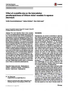
Figure 1. Schematic illustration of the HTS LSM experimental setup.
Lakeshore). The maximum achievable magnetization field using this system was 1.28 T with the HTSC samples clamped between the poles of the electromagnet. More details of this process can be found elsewhere [15]. Previous studies have demonstrated that the trapped field of a single-seeded HTSC bulk increases linearly with increasing static magnetization field, and this was found to be the case for samples Y1, G1, G2 and G3. However, the trapped field saturated at an applied magnetization field of 0.95 T for the rectangular three-seeded YBCO bulk sample, Y2 [15, 16]. As a result, static magnetization field conditions of 0.95 T, corresponding to a 40 A charging current from the Lakeshore power supply, were employed in this study to enable the fair comparison of the applied properties of all samples. After the unified magnetization procedure, the HTSC magnet was transferred into a liquid nitrogen (LN2) styrofoam container, which was assembled in a HTS LSM experimental setup developed in-house, as shown in figure 1. Figure 2 shows the photograph of the experiment system. The HTSC magnet secondary was further positioned over a flat single-sided three-phase copper-wound stator (Model LIMF111402A, HAN’s Motor) with an air gap of 10 mm whilst submerged in LN2 in the container. The stator pole employed iron teeth cores, in order to enhance the magnetic flux density, with a pitch of 42 mm. An frequency converter (Model PI7000, POWTRAN) and a common three-phase, sinusoidal ac supply using an armature current of 1–9 A at a frequency of 10.5–31 Hz were used to generate the travelling sinusoidal magnetic field over the stator. The HTSC magnet secondary was exposed to this travelling field, which generated associated thrust and normal forces. Subsequently, the release of
Figure 2. Photographs of the HTS LSM experiment system. (a) the
force measurement part; (b) the data-collecting part.
the HTSC magnet secondary will cause it to be driven forward along the forward direction of the travelling magnetic field, then the HTSC magnet secondary can be called as the mover of the HTS LSM system. The thrust and normal force generated were measured by the experimental arrangement shown in figure 1 by two sets of two directional piezoelectric force sensors along the x-axis and z-axis, respectively. The HTSC magnet secondary was attached rigidly to these four force sensors by four epoxy resin rods and a mechanical fixture. The output signal of each of the four force sensors was amplified in a two-stage process and then recorded by an Agilent 34401A digital multimeter. Finally, a Labview program was written to collect and analyze the magnitude of the variation in thrust and normal forces with time. All experiments presented in this paper were performed under the same conditions of an air gap of 10 mm, a stator frequency of 31 Hz and the armature currents of 3 A, 6 A and 9 A. Table 2 lists the maximum values of the travelling magnetic field densities along both the x- and z-axes, Bx and Bz, generated by the various armature currents at a distance of 10 mm from the bottom surface of the HTSC magnet secondary to the upper surface of the flat three-phase copperwound stator. Both Bx and Bz increase linearly with the armature current and decrease with a larger air gap. 3
Supercond. Sci. Technol. 27 (2014) 115016
J Zheng et al
Table 2. Maximum traveling magnetic field densities, Bx_max and Bz_max, at the height of 10 mm.
Armature Current Bx_max (T) Bz_max (T)
3A
6A
9A
0.017 0.015
0.034 0.028
0.051 0.042
and 3 show the variations of thrust and normal force with time for different armature currents. It can be seen that all the data exhibit the standard sinusoidal waveforms and the thrust is always 90 degrees ahead of the corresponding normal force attributed to the sinusoidal travelling magnetic field characteristic of the armature. Equations (1) and (2) for the distance and time varying magnetic flux densities parallel to the x and z directions, respectively, Bx and Bz, can be used to explain the observed sinusoidal thrust and normal force properties of the HTS LSM system. ⎛ 2π ⎞ B x (x , t ) = B x _ max sin ⎜ 2πft − x⎟ ⎝ λ ⎠
(1)
⎛ 2π ⎞ Bz (z , t ) = Bz _ max sin ⎜ 2πft − z⎟ ⎝ λ ⎠
(2)
where Bx_max, Bz_max are the corresponding maximum magnetic field density components, as listed in table 2, 2πf is the time phase parameter and 2πx/λ and 2πz/λ are the space phase parameters along the x and z directions. The space phases, 2πx/λ and 2πz/λ, are constants in this case, since the HTSC magnet secondary was fixed above the HTS LSM primary in the static studies performed here. According to equations (1) and (2), the travelling magnetic field demonstrates the standard sinusoidal variation with time. As a result, the x-axis and z-axis components of the Lorentz force (i.e. the static thrust and the normal force of the HTSC magnet secondary) should exhibit a periodic sinusoidal variation, which has been verified experimentally as shown in figures 3 and 4. It can be concluded from figure 3 that, for superconducting samples of the same diameter and the same armature current, the thrust observed between the flat threephase copper-wound stator and HTSC magnet secondary generated by the GdBCO-Ag bulk superconductor is much larger than that generated by YBCO. From figure 4, it should be noted that the average normal force is not zero but positive, as is the average thrust in figure 3. The effect of the normal force is to repel the HTSC magnet secondary vertically from the stator, which could enhance the levitation capability if the HTS LSM system is employed to propel the HTS Maglev vehicle. If the magnetization of the HTSC magnet is reversed, the positive gain in levitation from the HTS LSM system will effectively become a negative force (attraction), which will add undesirable load to the prime mover and reduce the load performance of the HTS Maglev system. As shown in figure 4(b), the GdBCO-Ag bulk superconductor generated a maximum normal force of about 5.51 N at an armature current of 3 A, which is slightly higher than the 5.22 N normal force produced by a NdFeB secondary magnet of the same diameter (30 mm) and thickness (18 mm) in an identical LSM experimental arrangement [7]. This is significantly higher than the normal force of 4.22 N generated by the YBCO bulk superconductor at an armature current of 3 A in figure 4(b). As a result, it appears that GdBCO bulk superconductors have clear potential to compete with conventional permanent magnet for LSM applications.
Figure 3. Thrust curves of two different HTSC magnets with the
same diameter of 30 mm. (a) The YBCO bulk magnet secondary; (b) The GdBCO-Ag bulk magnet secondary.
3. Results and discussion The time dependent thrust and normal force measurements were converted into the same time phase to enable effective comparison of the results. 3.1. Effect of different HTSC bulk material as secondary magnet
Firstly, two 30 mm diameter samples of different HTSC material, Y1 and G2, were magnetized as the secondary of the experimental HTS LSM system under identical conditions (40 A/0.95 T of the Lakeshore magnetizing system). Figures 2 4
Supercond. Sci. Technol. 27 (2014) 115016
J Zheng et al
Figure 5. Comparison of the thrust and normal force peaks per unit thickness for the YBCO and GdBCO-Ag bulk superconductors with the same diameter (30 mm).
trapped field gradient to critical current density, Jc,
(
dBtrap / dr = μ 0 Jc = 4π × 10−7Jc A / m2
)
(3)
As a result, the higher field trapping ability of GdBCOAg is due to the higher critical current density Jc in this material, which yields improved force performances for the HTS LSM system, since the secondary magnet diameters, r, are the same. Furthermore, figure 5 suggests that the increase in force ratio with armature current is quite different for the two bulk HTSC materials. For example, the thrust increase ratio of 32.8% for the GdBCO-Ag secondary is about two times that of the normal force increase ratio of 16.5%. The thrust increase ratio of 8.0% for the YBCO secondary, however, is almost the same as the normal force increase ratio, as shown in figure 5, and the two peak force density curves are nearly parallel. Taking the 9 A armature current experiment as an example, the thrust increase ratio of GdBCO-Ag compared to YBCO is 65.42%, whereas the normal force increase comparison ratio is relatively small (24.48%). However, from the point of view of the conventional linear motor in which the normal force provides attraction, the increased normal force with increased armature current for the GdBCO-Ag magnet secondary counters the reduction in levitation capability for the HTS Maglev application. At the same time, compared to the YBCO magnet secondary, the current enhancement produces a prominent enlargement in thrust, which will increase the efficiency of the linear motor and further provide higher propulsion acceleration for a fully superconducting HTS Maglev design.
Figure 4. Normal force curves of two different HTSC magnets with
the same diameter of 30 mm. (a) The YBCO bulk magnet secondary; (b) The GdBCO-Ag bulk magnet secondary.
Figure 5 compares the peak thrust and normal force per thickness for the 30 mm diameter YBCO and GdBCO-Ag bulk superconductors for different armature currents. It is clear that the peak thrust and normal forces increase linearly with the increased armature current independently of whether the secondary material is YBCO or GdBCO-Ag. However, the GdBCO-Ag secondary, as the potentially better performing HTSC magnet, exhibited a larger force density than the YBCO secondary under the same magnetization condition. As shown in figure 5, the peak thrust per thickness from the GdBCO-Ag secondary is typically 4.47 times larger than that from the YBCO secondary. The peak normal force per thickness is also around 1.80 times larger than that from the YBCO secondary, which can be explained by the data from the magnetization measurements. The maximum trapped magnetic field of the GdBCO-Ag bulk is 0.627 T for an applied magnetization current of 40 A, whereas it is only 0.320 T for the YBCO bulk (i.e. only half the value for GdBCO-Ag). The critical state model can be used to relate
3.2. Size effect of the HTSC secondary
In view of their enhanced performance, GdBCO-Ag bulk superconductors of different sizes, G1, G2, and G3, were tested to investigate the effect of size on the HTS secondary. Although the GdBCO-Ag samples were increased in diameter by a consistent amount, their size remained smaller than the stator pole pitch (42 mm). The insets to figures 6(a) and (b) 5
Supercond. Sci. Technol. 27 (2014) 115016
J Zheng et al
Figure 7. Thrust curves of the three-seeded YBCO secondary for
different armature currents.
Figures 6(a) and (b) also show that both the thrust and normal forces begin to saturate as the diameter of the HTSC secondary is increased. Taking the thrust as an example, the gradients of the force vs armature current data are 0.09, 0.39, and then decreases to 0.24 as the diameter of the HTSC secondary increasing from 20 mm to 30 mm and then to 40 mm. The HTSC secondary of maximum diameter (40 mm) did not produce the expected enhancement in force because the net force of the LSM is determined by the effective area of overlap between the primary and secondary components. Thus, although an important independent factor, it is not necessary to maximize the size of the HTSC secondary in a HTS LSM system. Furthermore, it is found that some unexpected weak distortions of the sinusoidal waveform occur for the largest GdBCO-Ag sample size, and especially for an armature current of 9 A. If the size of the HTSC secondary is enlarged continuously, the more obvious distortions in static force will further influence the practical achievable dynamic thrust and normal force, which may cause unnecessary disturbance in the HTS LSM subsystem acting on the stable HTS Maglev system. The unwanted phenomena of the armature current of 9 A in figure 6 are due primarily to the size of the 40 mm diameter sample, which is close to the size of the primary pole pitch (42 mm) of the HTSC secondary of the experimental HTS LSM system. More experiments on the larger sized HTSC secondary of the three-seeded YBCO sample, Y2, were performed to verify that the size of the stator pole pitch is the critical factor for the corresponding single HTSC secondary pole. Figure 7 shows clearly that the use of a HTS secondary (based on the threeseeded sample) that is larger than the primary pole pitch yields an even more serious distortion of force. To exclude the possible influence of the sample characteristics like geometry, shape and so on, a second orientation of the same HTSC secondary (i.e. across the stator) was investigated, which differs from the common orientation (i.e. along the stator). The results of this experiment are compared in figure 8. Here sample Y2 is oriented across the stator, in which the pole size of the HTS secondary (32 mm) is still smaller than the pole pitch (42 mm) of the stator. It can be seen that the data still exhibits the
Figure 6. Force density curves of the GdBCO-Ag superconducting
magnet secondary with different diameters with an armature current of 9 A. (a) Thrust per thickness; (b) Normal force per thickness. The insets show the variation in peak forces with armature current.
compare the increase in the force densities with increased armature current for the different-sized GdBCO-Ag magnet secondaries. As shown in figure 6, the HTS LSM motor exhibits larger forces for larger sized HTSC secondaries. This can be explained by the basic calculation formulas for the thrust and the normal forces, applicable to a cylindrical bulk HTSC; Fx / h = πAR 3Jc⋅ dB x / dx
(4)
Fz / h = πAR 3Jc⋅ dBz / dz
(5)
where A is a constant, R the radius of inductive current loop, h the thickness of bulk HTSC, and Jc is the critical current density of the bulk HTSC. A larger size bulk would mean a larger inductive area, which allows a larger inductive current loop and, in turn, leads to increased thrust and normal force. 6
Supercond. Sci. Technol. 27 (2014) 115016
J Zheng et al
potential secondary magnets with higher critical current density Jc and trapped fields bring enhanced force performance compared with the other HTS materials for the HTS LSM application. Moreover, for further development of the HTS LSM design, the pole pitch of the primary should be matched to the length of one HTS secondary magnet. Both thrust and normal force increase, saturate and then distort when the HTS secondary magnet size approaches incrementally to the pole pitch of the primary in the experiments performed here. One single, longer HTS secondary magnet can produce unnecessary disturbance in the HTS LSM system. As a result, the multi-pole bulk-type HTS LSM design has significant potential for this application, and should form the focus of further research. Comparison of the properties of the multi-seeded sample with that of a four 2G HTS coil LSM suggests clear potential performance advantages in LSM for bulk HTS, including a smaller volume, a more compact structure and a larger thrust.
Figure 8. Comparison of thrust comparison for the three-seeded
YBCO secondary with two different orientations to the stator.
standard sinusoidal waveform, in contrast to samples Y1, G1 and G2. It is further verified that both the thrust and the normal force are sensitive to the ratio of the stator pole pitch and the HTSC magnet secondary sizes. Furthermore, the measured thrust can increase by 9.34 times for a 3 A armature current and 4.34 times for a 9 A armature current by using orientation to adjust the effective secondary size from 32 mm (across the stator) to 64 mm (along the stator). From the viewpoint of the motor design, for the case of the 64 mm bulk magnet along the stator, the experimental LSM system worked effectively as a multi-pole LSM system, since the three-seeded, Y2, HTSC magnet acted effectively as three magnet poles for the secondary. Thus, the multi-pole HTSC magnet secondary will be more beneficial to future HTS LSM designs attributing to the potential thrust enhancement of dozens of times. Compared with the experimental four 2G HTS coil magnets/poles LSM design in [6], this multi-pole bulk-type HTS LSM demonstrates almost two times the peak thrust from 54 N to 102 N based on the same LSM stator platform for an armature current of 8 A. This was charged with a dc current of 60 A for the case of the experimental four 2G HTS coil LSM, which is the maximum transport current carrying limit of the HTS coils. This study indicates clearly that the bulk-type HTS LSM offers more performance advantages including a smaller volume, a compact structure and a larger thrust.
Acknowledgements This work was supported partially by National Natural Science Foundation in China (51207132, 51307147 and 51375404), the Fundamental Research Funds for the Central Universities (2682014ZT25 and 2682013CX028), the State Key Laboratory of Traction Power at Southwest Jiaotong University (2013TPL_Z04) and the Engineering and Physical Sciences Research Council (EPSRC) in the UK.
References [1] [2] [3] [4] [5] [6] [7] [8] [9] [10] [11] [12] [13]
4. Conclusions
[14] [15] [16]
It is concluded from the fundamental studies of the HTS LSM system that GdBCO-Ag bulk superconductors used as
7
Hellinger R and Mnich P 2009 P. IEEE 97 1892 Wu M et al 1987 Phys. Rev. Lett. 58 908 Gieras J 2009 Electr. Rev. 85 1–20 Gamble B, Snitchler G and MacDonald T 2011 IEEE Trans. Appl. Supercond. 21 1083 Kusada S et al 2007 IEEE Trans. Appl. Supercond. 17 2111 Zheng S et al 2012 IEEE Trans. Appl. Supercond. 22 5200104 Li J et al 2010 IEEE Trans. Appl. Supercond. 20 929 Durrell et al 2014 Supercond. Sci. Technol. 27 082001 Stumberger G, Aydemir M, Žarko D and Lipo T 2004 IEEE Trans. Appl. Supercond. 14 54 Zheng L and Jin J 2011 J. Appl. Phys. 110 043915 Shi Y et al 2010 Physica C 470 685 Deng Z et al 2012 IEEE Trans. Appl. Supercond. 22 6800210 Hari Babu N, Iida K, Shi Y and Cardwell D A 2005 Appl. Phys. Lett. 87 202506 Werfel F N et al 2012 Supercond. Sci. Technol. 25 014007 Zheng J et al 2007 Mater. Sci. Forum 546–549 2079 Jing H et al 2013 Mater. Sci. Forum 745–746 185