dentistry journal Article
Effect of the Surface Treatment Method Using Airborne-Particle Abrasion and Hydrofluoric Acid on the Shear Bond Strength of Resin Cement to Zirconia Ju-Hyoung Lee 1 and Cheong-Hee Lee 2, * 1 2
*
Department of Dentistry, Catholic University of Daegu School of Medicine, Daemyung-4-dong, Nam-gu, Daegu 42472, Korea;
[email protected] Department of Prosthodontics, School of Dentistry, Kyungpook National University, 2-188-1 Samduk-dong, Jung-gu, Daegu 41940, Korea Correspondence:
[email protected]; Tel.: +82-53-650-4285; Fax: +82-53-622-7067
Received: 13 May 2017; Accepted: 14 July 2017; Published: 17 July 2017
Abstract: The purpose of this study was to evaluate the shear bond strength (SBS) of two different resin cements (Panavia F 2.0 (Kuraray Medical Inc, Okayama, Japan) and Variolink N (Ivoclar Vivadent AG, Schaan, Liechtenstein)) to 112 zirconia specimens with airborne-particle abrasion and 20%, 30%, or 40% hydrofluoric acid (HF) for 1 or 2 h. A total of eight specimens were used to observe the phase transformation after surface treatments. Six specimens were treated only with HF etching and the average surface roughness (Ra) was analyzed. A one-way ANOVA test was applied for SBS and the effect of HF concentration on Ra. An independent t-test was performed for the comparison of Panavia F 2.0 and Variolink N, and the influence of the HF application time on Ra. A higher HF solution increased SBS and Ra. HF etching produced a lower rate of monoclinic phase transformation. Panavia F 2.0 showed a higher SBS than Variolink N. Keywords: zirconia; airborne-particle abrasion; hydrofluoric acid; shear bond strength
1. Introduction Due to its aesthetic quality and strength, metal ceramic restoration, which is supported by the metal structure, has been used for a long period of time in the areas requiring aesthetics [1]. Metal coping and condensed opaque porcelain frequently causes over-contouring of the emergence profile, making the shape of the gingiva unnatural. Patients0 high expectations for aesthetics have led to the development of various dental materials and increased the use of all ceramic restoration without the underlying metal structure [2,3]. In particular, zirconia, an aesthetic and biocompatible material with high mechanical strength, has been widely used in clinical practice due to the development of CAD/CAM technology and dental optical scanners [4–8]. There have been many studies on adhesives for zirconia. However, unlike traditional ceramics, zirconia has a high crystalline phase content, which makes the surface of zirconia unable to be etched by a low concentration of HF [2,8–11]. Also, unlike in the use of other existing ceramics, the use of silane was reported to be ineffective due to the absence of silica components [2,11]. Mechanical or chemical methods have been attempted for a stable bonding between zirconia and resin cement [9,11–24]. In order to increase the mechanical bonding force by making the fine irregular structure, airborne-particle abrasion or abrasive paper was used [11–14]. A primer or cement containing 10-methacryloyloxydecyl dihydrogen phosphate (10-MDP) monomer has been used for chemical bonding [15,25]. The phosphate ester group of the MDP was reported to directly bond to metal oxide [15,25]. Another reaction might have been formed between the hydroxyl group in the MDP monomer and the hydroxyl group on the zirconia surface [9]. However, this reaction did not maintain
Dent. J. 2017, 5, 23; doi:10.3390/dj5030023
www.mdpi.com/journal/dentistry
Dent. J. 2017, 5, 23
2 of 12
the shear bond strength (SBS) after thermocycling [9]. By using the Cojet and Rocatec systems, silica was inserted on the surface of zirconia for mechanical and chemical bonding [9,15,17,18]. In recent years, studies have reported that the zirconia surface can be etched by corroding zirconia grains with high-concentration acids at room temperature [20–22]. However, the maximum application time was only 1 h and a comparison of SBS according to cement type was not undertaken in previous studies. This study evaluated the SBS of two resin cements to zirconia with airborne-particle abrasion and high-concentration HF etching for up to 2 h as a mechanical treatment. The null hypothesis was that the alumina airborne-particle abrasion and HF etching would not affect the SBS of resin cements to zirconia. 2. Materials and Methods 2.1. Zirconia Specimens and Surface Treatment Methods Commercial zirconia disc (Ceramil Zolid, Amann Girrbach, Koblach, Austria) was used in this in vitro study. By using an automatic cutting machine (G2 Concept, Schick Dentalgeräte, Schemmerhofen, Germany), 126 square-shaped specimens (15 × 15 × 1.5 mm) were prepared. One surface of each of the specimens was polished with up to 1200 grit size abrasive papers. A total of eight specimens were preserved for the analysis of the phase transformation following surface treatments. Thereafter, six specimens were also preserved for the analysis of average surface roughness (Ra) by only the HF etching procedure. As shown in Table 1, the rest of the specimens were divided into eight groups (n = 14) for SBS testing and debonded zirconia surface observation. The control group (C) was sintered in a furnace (Ceramill Therm, Amann Girrbach) according to the manufacturer's instruction (8 ◦ C per minute from 200 ◦ C to 1450 ◦ C, 2 h at a fixed temperature of 1450 ◦ C, and the cooling time) [21]. These specimens were air abraded with 110 µm alumina particles (Cobra, Renfert GmbH, Hilzingen, Germany) at 3.5 bars, for 10 s, at a distance of 15 mm from the nozzle of the sandblaster (Duostar, Bego, Bremen, Germany). The rest of the pre-sintered specimens were abraded from a distance of 100 mm, at 2 bars, for 5 s. These specimens were sintered. A confocal laser scanning microscope (CLSM) (LSM 700, Carl Zeiss Microscopy, Göttingen, Germany) with a 405 nm diode laser was used to measure the Ra of 20 specimens among group C as well as the abraded-sintered groups. Table 1. Experimental groups and various surface treatments. Group (n = 14)
Airborne-Particle Abrasion
HF Concentration and Dwelling Time
C NoHF 20HF1 20HF2 30HF1 30HF2 40HF1 40HF2
After sintering Before sintering Before sintering Before sintering Before sintering Before sintering Before sintering Before sintering
Not applied Not applied 20% for 1 h 20% for 2 h 30% for 1 h 30% for 2 h 40% for 1 h 40% for 2 h
Then, 14 specimens were named as group NoHF. Twenty percent, 30%, and 40% HF solutions were experimentally prepared using 48% HF solution (MKBH5499V, Sigma-Aldrich Co., St. Louis, MO, USA), distilled water, and an electronic scale. The abraded-sintered specimens and six preserved specimens were treated with 20%, 30%, or 40% HF solutions for 1 h or 2 h in a plastic box (Table 1). The conditioned specimens were cleaned with distilled water and then dried. The specimens were embedded by using auto-polymerizing acrylic resin (Orthodontic Resin, Dentsply, Milford, DE, USA) and metal molds.
Dent. J. 2017, 5, 23 Dent. J. 2017, 5, 23
3 of 12 3 of 12
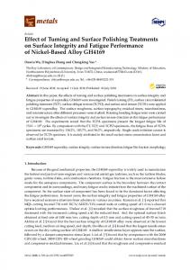
2.2. Bonding 2.2. Bonding and and Thermocycling Thermocycling Composite resin tubes (diameter: (diameter: 2.379 were fabricated fabricated using using light-polymerized light-polymerized flowable flowable Composite resin tubes 2.379 mm) mm) were resin (Tetric N-Flow, Ivoclar Vivadent AG, Schaan, Liechtenstein) and mold (Bonding Mold resin (Tetric N-Flow, Ivoclar Vivadent AG, Schaan, Liechtenstein) and mold (Bonding Mold Insert, Insert, Ultradent Products Inc, South Jordan, UT, USA) [22]. After injecting the flowable resin into the Ultradent Products Inc., South Jordan, UT, USA) [22]. After injecting the flowable resin into the mold, mold, light-curing unit unit (Elipar (Elipar TriLight, TriLight, 3M 3M ESPE, ESPE, St St Paul, Paul, MN, MN, USA) USA) was was applied appliedfor for20 20s.s. aa light-curing A stand stand was wasmade madeon onthe theplatform platform surveyor (Ney Surveyor, Dentsply A of of thethe castcast surveyor (Ney Surveyor, Dentsply Inc., Inc, York,York, UK) England) and specimens were placed on the stand. A 10-MDP-containing composite resin cement and specimens were placed on the stand. A 10-MDP-containing composite resin cement (Panavia F (Panavia F 2.0, Kuraray Inc,Japan) Okayama, and a conventional composite cement 2.0, Kuraray Medical Inc.,Medical Okayama, and aJapan) conventional composite resin cement resin (Variolink N, (Variolink N, Ivoclar AG) were After mixing the cement to the Ivoclar Vivadent AG) Vivadent were selected. After selected. mixing the cement according to theaccording manufacturer’s manufacturer’s two composite tubes were pressed into perpendicularly into the zirconia instructions, twoinstructions, composite tubes were pressed perpendicularly the zirconia specimens under specimens under about 500 g [23]. Residual cement around the margin was removed withthea about 500 g [23]. Residual cement around the margin was removed with a microbrush and microbrushwere and the specimens werefrom light-polymerized three sides for 30 s, 750 Mw/cm2, using 2 , using specimens light-polymerized three sides for from 30 s, 750 Mw/cm a light-curing unit a light-curing unit 3M ESPE) (Figure 1). (Elipar TriLight, 3M(Elipar ESPE)TriLight, (Figure 1).
Figure 1. 1. Bonded Bonded composite tubes on the embedded zirconia specimen using the resin cements. Figure
All specimens forfor 2424 h. h. TheThe specimens werewere divided into into two All specimens were wereimmersed immersedinindistilled distilledwater water specimens divided subgroups (the non-thermocycled group and the thermocycled group). The latter group was two subgroups (the non-thermocycled group and the thermocycled group). The latter group was thermocycled 5000 5000times timesbetween between °C and 55in°C in water bathsa dwelling with a dwelling of 30 s, thermocycled 5 ◦ 5C and 55 ◦ C water baths with time of 30time s, according according to ISO 10477 [22,26]. to ISO 10477 [22,26]. Test and and Debonded Debonded Zirconia Zirconia Surface Surface Observation Observation 2.3. Shear Bond Strength Test was performed performed at at aa crosshead crosshead speed speed of of 11mm/min mm/min in a universal The shear bond strength test was Testing System, System, Instron Instron Inc., Inc, Canton, GA, USA). The testing machine (3343 Single Column Universal Testing load was applied at the interface between the composite tube and the zirconia specimen until the automatically. composite tube was dislodged. The maximum load was recorded automatically. theSBS SBStest, test, randomly selected specimens Pt-coated ion sputter After the randomly selected specimens werewere Pt-coated by anby ionan sputter (E-1030,(E-1030, Hitachi Hitachi High-Technologies Corp,Japan). Tokyo, Anblinded observer blinded the surface treatment High-Technologies Corp., Tokyo, AnJapan). observer to the surfacetotreatment examined the examined surfaces the debonded with a field emission-scanning electron microscope (FE-SEM) debonded with a surfaces field emission-scanning electron microscope (FE-SEM) (SU8220, Hitachi (SU8220, Hitachi High-Technologies Corp). High-Technologies Corp.). 2.4. Phase Transformation Transformation Analysis 2.4. Phase Analysis and and Morphological Morphological Analysis Analysis X-ray Rigaku Corp, Corp.,Tokyo, Tokyo, Japan) Japan) was was used used to to detect X-ray diffraction diffraction (XRD) (XRD) (D/Max-2500, (D/Max-2500, Rigaku detect phase phase transformation by the HF etching. The diffractograms were obtained using cu-kα radiation at 40 kV and 200 mA, from 20° to 70° at the scan speed of 3°/min and a 0.02° step size; the peak intensity ratio was obtained automatically.
Dent. J. 2017, 5, 23
4 of 12
and 200 mA, from 20◦ to 70◦ at the scan speed of 3◦ /min and a 0.02◦ step size; the peak intensity ratio was obtained automatically. A scanning probe microscope (SPM) (NS20, Park Systems, Suwon, Korea) was applied to evaluate the Ra of HF-etched specimens. Three areas of a representative specimen of each group, without the airborne-particle abrasion process, were selected. Subsequently, 5 µm × 5 µm images with 256 × 256 pixels were taken by a using non-contact mode, with a scan rate of 0.5 Hz. 2.5. Statistical Analysis All statistical analyses were performed using SPSS 20.0 Statistics (IBM Co., Armonk, NY, USA). The level of significance of α = 0.05 was assumed to mark statistical significance. All results were described as the means ± standard deviation. A one-way ANOVA test followed by the least significant difference test for post hoc comparisons was performed for SBS and the effect of HF concentration on the Ra. For the comparison of Panavia F 2.0 and Variolink N, as well as the influence of the HF application time on the Ra, an independent t-test was performed. To examine the effect of thermocycling, a paired t-test was applied. 3. Results 3.1. Shear Bond Strength The SBS values of each group are presented in Tables 2 and 3. Regardless of thermocycling and cement, a higher HF concentration significantly increased SBS. Before thermocycling, the SBS of group 20HF2 with Panavia F 2.0 and group 20HF1 with Variolink N were superior to the SBS of group C with Panavia F 2.0 or Variolink N, respectively. After thermocycling, group 30HF2 with Panavia F 2.0 and group 30HF1 with Variolink N surpassed the SBS of group C with Panavia F 2.0 or Variolink N, respectively. In group 20HF and group 40HF, the prolonged application time of HF did not considerably increase SBS. However, the SBS of group 30HF2 increased as compared to group 30HF1. Group 30HF2 bonded with Panavia F 2.0 showed the highest SBS among the non-thermocycling groups. After thermocycling, group 40HF1 cemented with Panavia F 2.0 showed the highest bond strength. The SBS of group C was superior to the SBS of group NoHF. Panavia F 2.0 produced a significantly higher SBS than Variolink N (Table 3). After thermocycling, the SBS of all groups reduced regardless of cements. Table 2. Means and standard deviation of shear bond strength for each group (MPa).
Group C NoHF 20HF1 20HF2 30HF1 30HF2 40HF1 40HF2 p-value a,b,c,d
Pre-thermocycling Panavia F 2.0
Variolink N
3.96 ± 0.42 c 1.88 ± 0.96 d 4.46 ± 0.84 c 5.84 ± 1.47 b 5.52 ± 1.07 b 7.94 ± 1.05 a 7.71 ± 0.64 a 7.62 ± 1.67 a