Effect of Time Delay on TeleSurgical Performance Mitchell J.H. Lum, Jacob Rosen, Thomas S. Lendvay, Mika N. Sinanan, Blake Hannaford
Abstract— In the area of surgical robotics no standard means of performance evaluation has been established. Thousands of surgeons have gone through the SAGES FLS Program, and the psychomotor skill portion of the program is considered the gold standard in laparoscopic skills evaluation. This research describes the use of the FLS Block Transfer task to evaluate the performance of both surgeons and non-surgeons teleoperating under different time delay conditions on the University of Washington RAVEN Surgical Robot. Time delays of 0ms, 250ms, and 500ms were used and a statistically significant difference in mean block transfer time as well as mean tool tip path length were shown. For this task no significant difference was shown between the surgeon and non-surgeon groups. Clearly surgeon input and feedback is key to surgical robotic system development, but this result implies that non-surgeon subjects can be tested for simple usability evaluations.
I. INTRODUCTION Robot assisted surgery has revolutionized the way in which many surgical interventions are performed resulting in better patient outcomes. Telesurgery on a human patient was accomplished on September 9, 2001 by Marescaux and Gagner. In collaboration with Computer Motion, they used a modified Zeus system to teleoperate between New York City and Strasbourg, France under a 155ms time delay using a dedicated Asynchronous Transfer Mode (ATM) communication link [9]. Although this was a one-time experiment, telesurgery has the potential to deliver expert surgical care to anywhere in the world. A. Active Research In Asia, a group from the University of Tokyo has recently been working on a new telesurgery system [10], and has completed laparoscopic cholcystectomy on a porcine model between sites in Japan, and moret recently between Japan and Thailand. They state the experimental result as “a laparoscopic cholecystectomy on a pig was successfully carried out. The completion time of the surgery was about 90 min, which is roughly equal to a conventional laparoscopic cholecystectomy” [1]. Morel’s group from University of Paris, Laboratoire de Robotique de Paris (LRP) uses a spherical mechanism similar to the RAVEN [13]. Their device is relatively simple, but what is novel is that it moves the trocar in addition to the tool. This has allowed them to embed force sensors in the M. Lum, B. Hannaford, Electrical Engineering, University of Washington, Seattle, WA USA @u.washington.edu J. Rosen, Computer Engineering, University of California, Santa Cruz, CA USA
[email protected] T. Lendvay, Dept. of Urology, Seattle Children’s Hospital, Seattle, WA USA
[email protected] M. Sinanan, Dept. of Surgery, University of Washington, Seattle, WA USA
[email protected]
device that give a direct reading of the forces at the tool tip, instead of the combined interaction forces of the tool/tissue and trocar/abdomen. Berkelman, at the University of Hawaii, Manoa, has further developed the Light Endoscopic Robot (LER), on which he began work in TIMC-IMAG laboratory in Grenoble. This device was originally designed to guide an endoscopic camera, but is now capable of holding disposable endoscopic graspers [2]. A tool with wrist articulation is currently in development. B. SAGES Fundamentals of Laparoscopic Surgery The Society of American Gastrointestinal Endoscopic Surgeons (SAGES) formed a committee for the Fundamentals of Laparoscopic Surgery (FLS) in the late 1990’s. Peters [11] discusses the background behind the development of the FLS program. The program features both cognitive surgical understanding as well as hands-on technical skills. The technical skills set is derived from the McGill University MISTELs program [3]. The FLS program has been implemented around the world with thousands of surgeons from first year residents to veteran surgeons tested. It provides a well structured and well defined quantitative means by which a surgeon’s skill can be evaluated. C. TeleRobotic FLS The UW RAVEN Surgical Robot is a system designed for telesurgical applications. During its initial validation and field experiments, the RAVEN was tested in a number of teleoperation modes including operating through a digital data link on board an unmanned aerial vehicle [6] and in the Aquarius Undersea Habitat [5]. The system has also teleoperated with the Patient Site in Seattle, WA and the surgeon site located in Cincinnati, OH; Tokyo, Japan; Montpellier, France; and London, England connecting through commercial Internet. Network statistics were collected on packet loss, delay and correlation. These early experiments provided motivation to more carefully study the delay effect in telesurgical performance. This manuscript describes the method by which the FLS Block Transfer (Pegboard Transfer 1 ) was adopted as a standardized task for telerobotic surgical performance evaluation. Previously, a pilot study with only three non-surgeon subjects was performed to obtain preliminary results and debug the 1 The Pegboard Transfer is often referred to in short as “Peg Transfer,” which has lead to some confusion, since blocks are being transferred not pegs. Some surgeons refer to the task as “Block Transfer” to make the name more descriptive of the task performed. For TeleRobotic FLS we use Block Transfer synonymously with the SAGES Pegboard Transfer.
method [7]. This study reports the results of six surgeons and nine non-surgeons performing the Block Transfer task under three different time-delay conditions.
TABLE I D ISTANCES BETWEEN PAIRS OF PEGS ON THE FLS B LOCK T RANSFER TASK B OARD Peg Number 1 2 3 4 5 6
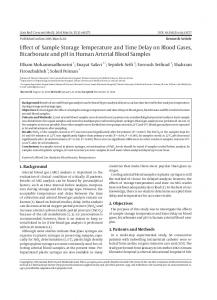
II. METHODS Of the five FLS skills tasks, three are directly applicable for use with surgical robotic systems and have been adopted into the TeleRobotic FLS scheme. The tasks are Block Trasfer, Intracorporeal Knot Tying, and Pattern Cutting. This research used the Block Transfer task. This section describes the experimental methods in detail. A. TeleRobotic Block Transfer In the SAGES FLS Block Transfer, the subject is allowed to start with all blocks on either side, then transfer all blocks from one side to the other and then back again. It is only considered an error if a block is dropped outside the viewable area, bounded by a black rectangle on the task board (see Figure 1). The score is a proprietary formula based on an aggregate of completion time with a penalty for errors.
Distance (cm) 3.8 5.7 5.7 5.2 5.2 6.9
ends when the sixth block is placed. From the “lap times,” the “split times,” or individual block transfer times, may be determined. The time-based results can either be reported as the average individual block transfer time or the average time for all six blocks, as well as the number of blocks dropped and recovered and the number of blocks dropped and not recovered. Optimally the surgeon performs the task carefully enough that no errors occur.
UW BioRobotics Lab TeleRobotic FLS 6 6
3
5
Fig. 1.
3
4
2
2
FLS Blocks being transferred using RAVEN
The TeleRobotic Block Transfer, by contrast, is more structured to eliminate variability between subjects due to different or evolving “block moving strategies.” A single trial consists of moving all six blocks from the left side to the right side and then back again. There is a pause between leftto-right and right-to-left. Each peg is numbered as shown in Figure 2. The trial begins with the tools touching or near the first block. The blocks must be moved in numeric order from the peg on one side to the corresponding peg on the other side. Should the subject attempt to move blocks out of order or to the wrong peg, the experimenter will remind the subject that order matters. Errors are defined as any time a block is not set down on its corresponding numbered peg. This often occurs in the form of a dropped block. If a block is dropped and recovered, that is marked as one type of error. If a block is dropped and not recovered that is noted as another type of error. For system development purposes the experimenter should note the cause of the error if that can be immediately determined. When the experimenter says “Go!,” the time starts. The individual “lap time” for each block is recorded and measured at the point where the block is fully in contact with the surface of the pegboard (i.e. not partially dangling on the peg or partially sitting on an adjacent block). The time
5
4
1 1
Left Fig. 2.
Right TeleRobotic FLS peg numbering
B. Time Delay Experiments with the UW RAVEN Surgical Robot This section describes a specific implementation of the TeleRobotic FLS methodology to study the effect of time delay on performance using the UW RAVEN Surgical Robot [8]. This experimental set-up was used for both the pilot study [7] and this study. Real Teleoperation: In an actual teleoperation, physical distance and a real network separate the patient and surgeon sites with time-varying delays. When a surgeon makes a gesture using the master device, motion information is sent through the network to the Patient Site with a network time delay (Tn ). The manipulator moves and the audio/video (a/v) device observes the motion. Digital a/v is compressed (Tc ), sent from the Patient Site to the Surgeon Site through the network (Tn ), then decompressed (Td ) and observed
by the surgeon. The surgeon has experienced a total delay T = 2Tn + Tc + Td , from the time (s)he made the gesture to the time that action was observed. Emulated Teleoperation: In the emulated teleoperation, the Surgeon and Patient sites are not separated by physical distance. Instead they are connected through a Linux PC with two network cards running NISTNET that emulates a real network. This emulator allows the experimenter to adjust the average packet delay between the Surgeon and Patient sites [12]. The a/v feed is connected directly from the camera at the Patient Site to the monitor at the Surgeon Site through S-video eliminating any delay due to compression/decomression. The surgeon experiences a total delay, Te due to the emulator, from the time (s)he made the gesture to the time that action was observed. Network (Tn)
Surgeon Site
A/V Decomression (Td)
Patient Site
Network (Tn)
A/V Compression (Tc)
Te = 2*T n + T c + T d
Emulator (Te)
Surgeon Site
Fig. 3.
Direct A/V (T=0)
Patient Site
Teleoperation communication flow
The flow of information is illustrated in Figure 3. By setting Te = 2Tn + Tc + Td , one can emulate any real teleoperation condition. In this study, because the camera is connected directly to the monitor, there is no degradation of the video or audio signals due to compression techniques. Performance in telesurgery as a function of video degradation could be the subject of a future study, but is not a factor in this case. 1) Experimental Set-up: The RAVEN Patient and Surgeon sites are located in the same room and are connected through the network emulator. The video feed comes directly from a Sony DCR-VX1000 3-chip digital video camera to a Sony Trinitron PVM-14M2MPU color monitor through an S-video cable. 2) Training: Each subject received specific training on the system prior to the main study. Each subject watched an orientation video about the RAVEN surgical robot and how to perform telemanipulation tasks. The video broke down manipulation into three parts: (1) positioning, (2) orienting, and (3) grasping, first with dominant hand, then with nondominant hand. The subjects were instructed on three tasks
TABLE II N UMBER OF REPETITIONS FOR EACH OF THE TRAINING TASKS Task 1A, 1B 2A, 2B 3A, 3B
No Delay 25 15 12
Delay (250ms) 10 10 10
(described below) that would enable them to successfully teleoperate using the RAVEN. During the pilot study [7], each task was performed until the subject’s completion time for that task did not improve over three trials. Based on subject feedback as well as analysis of the training data, a fixed number of repetitions for each of the tasks were performed for this study (see Table II. Once the subject had completed a tasks (s)he was allowed to move on to the next task. The subjects trained until they had completed all three tasks. The subjects then repeated the same training tasks under a delay condition of 250ms. By first training the subjects with no-delay, they were able to learn the psychomotor skills necessary to telemanipulate objects under the most ideal conditions. Then, by repeating the training tasks under a delay condition, they learned to accommodate for delay. Ideally, in order to reduce subject fatigue, the nondelay and delay training were completed on separate days. In practice, due to scheduling this was not always possible. The training task board was built on a 4” x 2.5” piece of plexiglass. Six 1” x 1/4”-20 countersink screws were arranged in a grid of two rows of three. The screws were capped by 1” pieces of 1/4” inner-diameter rubber tubing and arranged with 1” spacing between each of the three columns and 7/8” spacing down between each of the two rows. Each of the six pegs were numbered 1-6 as shown in Figure 4. The following list describes the training tasks for the dominant hand. Tasks 1B, 2B and 3B, the tasks for the non-dominant hand, are similar. • Task 1A Dominant Hand Positioning Using the dominant hand’s tool, touch each peg in sequence 1 through 6, while keeping the non-dominant hand’s tool in the field of view. You will know you’ve touched the peg when you see it deflect. • Task 2A Dominant Hand Orientation Using the dominant hand’s tool, orient the grasper tips and place the tips into the center of each peg in sequence 1 through 6 while keeping the non-dominant hand’s tool in the field of view. • Task 3A Dominant Hand Grasping Using the dominant hand’s tool, open the grasper tips, place the tips with one jaw in the center of each peg and one jaw on the outside of the peg, then grasp the peg wall. Grasp each peg in sequence 1 through 6 while keeping the non-dominant hand’s tool in the field of view. When grasping with the right tool, grasp the right side of the peg. When grasping with the left tool, grasp the left side of the peg. 3) Warm-up: If the subject had been away from the system for more than an hour, they were presented with
III. R ESULTS
Fig. 4.
Training Task Board
6) Subject Population: Fifteen subjects, six surgeons and nine non-surgeons, nine male and six female, ages ranging from 18 to 43, participated in this study under University of Washington Human Subjects Approval Number 01-825E/B07. The subjects performed the training tasks first with no delay, and then with 250ms delay, in order to learn how to telemanipulate using the RAVEN. Within one week from the start of their training, they returned to perform the Time Delayed Block Transfer experiment. A. Training
Treatment A B C
Delay (ms) 0 250 500
TABLE III T HREE DIFFERENT CONDITIONS WERE PRESENTED TO EACH SUBJECT
the training task board and were required to perform a 5minute warm-up during which they performed the training tasks. The warm-up was performed with no time delay and subjects were allowed to move at their own pace. 4) Experimental Design: In this study, three delay conditions were investigated (summarized in Table III): 0ms (Treatment A), 250ms (Treatment B), and 500ms (Treatment C). Subjects performed three repetitions of each of the three treatments for a total of nine trials. The nine trials were arranged in a pseudo-random fashion. The treatments were grouped into three bins so that each bin contained one of each of the three treatments. Six possible bins resulted from the permutations of the three conditions. When subjects arrived they performed an urn sampling without replacement of three numbered balls from a box originally containing six balls. The order of the balls determined the order of the bins. For example if the subject drew 3, then 5, then 1, the order of their nine trials would be (B, A, C), (C, A, B), (A, B, C). Designing the order so that the subject received one of each of the treatments before receiving a second (and so on) meant that, if a learning effect was present during the experiment, the improvement in performance would be distributed more evenly across the different treatments. Between each of the trials, the subjects received a short break, and after the third and sixth trial, the subjects were required to take a minimum 5-minute break to help minimize fatigue. Before each trial the subject was told which treatment they were being given to allow them to prepare their strategy for accommodating for delay. 5) Stated Objective: The subjects were told that, although they were being timed, speed should not be their optimizing factor. They were instructed that the goal of the exercise was to transfer each block carefully, so that no errors were made (no dropped blocks) at whatever speed was necessary to insure successful transfer.
Of the 15 subjects who started the training, 14 finished. Completion of the training portion of this experiment was a prerequisite to move to the Block Transfer task. B. Block Transfer under Time Delay Five surgeons and nine non-surgeons completed the main portion of this experiment for a total of 14 subjects. Each subject performed three repetitions of each of the three treatments, for a total of 108 block transfers (36 for each treatment) with the time for each transfer recorded. For each subject, the mean block transfer time for each of the three conditions was calculated. A linear regression was fit to these times and, in all but one case, was fit with an R2 > 0.969. The slope of the linear fit to block transfer time versus delay represents the subjects’ sensitivity to delay (how much their completion time increases with increasing delay) and the y-intercept represents their estimated performance in the nominal (no delay) condition. The results are listed in Table III-B. Errors were defined as a block that was dropped. These were further classified as dropped blocks that were recovered and dropped blocks that were unrecovered. While an aggregate score or weighting is not given to each of the two types of errors, subjects were told that a block that was not recovered would be considered a “worse” error. Table V lists the total number of errors from each subject over three repetitions of each of the three treatments and the total number of errors for the experiment. While the TeleRobotic FLS as described in this manuscript reports Block Transfer times and two types of errors, the RAVEN inherently is able to capture motion data as well. Position data of each tool was recorded during the trials. For each trial the distance traversed by each tool was calculated. The path length is the sum of the distance traversed by the left and right tools. Table III-B shows the average path length for each subject for each of the delay conditions. Path length data from Subjects 1 and 2 were not properly captured and cannot be reported. C. Statistical Analysis Statistical analysis was performed using R. A two-way analysis of variance (ANOVA) was used to determine the significant results. Three analyses were performed separately. The first used block transfer time as the response variable;
TABLE IV S UBJECT BY S UBJECT M EAN B LOCK T RANSFER T IMES REPORTED IN SECONDS FOR EACH OF THE THREE CONDITIONS . T HE MEAN TIMES FOR EACH SUBJECT WERE FITTED TO A LINEAR REGRESSION . T HE D ELAY S ENSITIVITY IS THE SLOPE OF THE LINEAR FIT. T HE R2 VALUE ASSOCIATED WITH THE LINEAR REGRESSION IS ALSO LISTED .
Subject#
Surgeon
Treatment A
Treatment B
Treatment C
1 2 3 4 5 6 7 8 9 10 11 12 13 14 15
N N N N N Y N N Y Y Y Y Y N N
31.74 33.90 48.8 43.59 22.45 38.03 32.15 53.84 40.95 36.79 NC 44.18 23.32 33.96 33.1
43.13 46.98 74.46 66.60 34.65 51.47 43.93 74.76 68.61 60.94 NC 60.53 33.08 40.69 48.87
64.63 65.59 90.34 104.98 46.19 69.34 64.75 103.94 88.42 80.03 NC 86.33 52.4 66.41 71.38
Delay Sensitivity (ms/ms) 65.78 63.38 83.08 122.78 47.48 62.62 65.20 100.20 94.94 86.48 NA 84.30 58.16 64.90 76.56
R2 0.9695 0.9900 0.9819 0.9795 0.9997 0.9934 0.9750 0.9910 0.9910 0.9955 NA 0.9835 0.9652 0.8975 0.9898
TABLE V E RRORS FOR EACH OF THE THREE TREATMENTS OVER THREE TRIALS FOR EACH AND THE TOTAL ERRORS OVER ALL NINE TRIALS Subject#
Surgeon
1 2 3 4 5 6 7 8 9 10 11 12 13 14 15
N N N N N Y N N Y Y Y Y Y N N
Treatment A rec unrec 0 0 1 1 2 0 0 0 0 0 2 0 3 0 0 0 1 0 1 1 NA NA 2 0 0 0 2 1 0 1
the second used the number of error; the third used tool tip path length as the response variable. The difference in mean block transfer time between each of the three treatments (0ms, 250ms, and 500ms delay) is statistically significant, and is illustrated in Figure 5. The difference in mean path length between each of the three treatments is significant as illustrated in Figure 6. While the stated objective of the task was to minimize errors some errors occurred but the number of errors in response to delay effect and surgeon effect was not significant. It is possible that if the task was more technically challenging,
Treatment B rec unrec 1 0 0 2 1 1 0 1 0 0 0 1 1 0 0 0 0 0 1 0 NA NA 1 1 1 0 0 0 1 0
Treatment C rec unrec 0 0 0 0 0 0 1 2 0 1 1 0 2 0 0 0 1 1 2 2 NA NA 1 1 0 0 3 0 0 0
Total 1 4 4 4 1 4 6 0 3 7 NA 6 1 6 2
the frequency or severity of errors would start to differentiate between subjects with more and less skill. The difference in mean block transfer between surgeons and non-surgeons is not statistically significant. The difference in mean path length between surgeons and non-surgeons is significant at the 0.05 level. IV. DISCUSSION At the outset, there was a hypothesis that surgeons might be more careful and therefore less prone to errors. Another possibility is that surgeons who perform MIS cases would
TABLE VI S UBJECT BY S UBJECT M EAN B LOCK T RANSFER PATH L ENGTH REPORTED IN METERS FOR EACH OF THE THREE CONDITIONS . T HE MEAN PATH LENGTH FOR EACH SUBJECT WERE FITTED TO A LINEAR REGRESSION . T HE D ELAY S ENSITIVITY IS THE SLOPE OF THE LINEAR FIT IN MILLIMETERS OF INCREASED PATH LENGTH PER MILLISECOND OF INCREASED DELAY.
T HE R2 VALUE ASSOCIATED WITH THE LINEAR REGRESSION IS ALSO LISTED .
Subject#
Surgeon
Treatment A
Treatment B
Treatment C
1 2 3 4 5 6 7 8 9 10 11 12 13 14 15
N N N N N Y N N Y Y Y Y Y N N
NC NC 5.986 8.2088 5.3507 7.6223 6.912 8.5130 8.5280 9.4084 NC 8.7550 7.1420 7.5452 7.7066
NC NC 7.2858 11.7815 6.2531 8.8765 7.7486 11.3580 10.2894 15.0260 NC 10.9600 8.6191 8.3858 10.4009
NC NC 8.1057 16.3581 7.3290 9.7528 9.4067 13.4632 11.7445 15.1186 NC 14.0210 10.4480 13.3066 11.6348
Delay Sensitivity (ms/ms) NA NA 4.24 16.29 3.96 4.26 4.99 9.90 6.43 11.42 NA 10.53 6.61 11.52 7.86
TABLE VII ANOVA R ESULTS
R2 NA NA 0.9832 0.9950 0.9974 0.9896 0.9652 0.9926 0.9970 0.7622 NA 0.9913 0.9962 0.8568 0.9560
20
be more adapted to the lack of depth perception. It was also suggested that surgeons would be better at accommodating to delay. The statistical analysis shows that there is no significant difference between surgeons and non-surgeons for these telerobotic manipulation tasks. Clearly, the ability to perform surgery extends far beyond the psycho-motor skill of moving blocks on a pegboard, requires (among many other skills) a high level of cognitive ability, familiarity with anatomy, and the ability to deal with unexpected problems. However, for the purposes of the development of a surgical robot, these results imply that performing usability or evaluation experiments with non-surgeons may be adequate when using simple tasks such as the Block Transfer. Complex tasks such as suturing, may require surgeon participation. In addition, the effects of delay may be more dependent on the individual than on the individual’s surgical expertise.
40
60
Path Length
Sig. < 2e − 16 0.8113 0.9728 1.978e − 08 0.01962 0.74864
80
Time
Source Delay Surgeon? Delay*Surgeon? Delay Surgeon? Delay*Surgeon?
Time (sec)
Measure
100
120
Delay Effect
0
250
500
Delay (ms)
Fig. 5. Delay Effect versus block transfer time. 0ms average block transfer time was 36.95sec; 250ms average block transfer time was 53.60sec; 500ms average block transfer time was 75.44sec.
V. CONCLUSIONS AND FUTURE WORKS The development of the TeleRobotic FLS tasks has established a standardized means by which any group working in the area surgical robotics can conduct performance testing for a multitude of hypotheses. The SAGES FLS skills tasks kit
25
Delay Effect
[3]
15
[4]
10
TotalPath (m)
20
[2]
5
[5]
[6] 0
250
500
Delay (ms)
Fig. 6. Delay Effect versus path length. 0ms average tool tip path length was 7.629m; 250ms average tool tip path length was 9.781m; 500ms average tool tip path length was 11.724m.
can be readily purchased and is already a standard amongst many surgical residency programs. Standardizing on TeleRobotic FLS will benefit surgical robotics researchers much in the same way it has benefited surgeons - it creates a common reference frame in which to understand each others results. Currently, an Interoperable Teleoperation Protocol (ITP) is being developed between the University of Washington, SRI International, Tokyo Institute of Technology and other Universities. An initial ITP experiment with the University of Washington, and Tokyo Institute of Technology investigates the performance of two different master devices controlling the RAVEN using the Block Transfer Task [4]. VI. ACKNOWLEDGMENTS The authors gratefully acknowledge technical contribution from Diana C.W. Friedman and Ganesh Sankaranarayanan of the UW BioRobotics Lab. The authors would also like to acknowledge the participants in this study for being so generous with their time. Funding for the development of the RAVEN was provided by US Army MRMC grant number DAMD17-1-0202. Additional support for this work was provided by Intel Research Seattle. R EFERENCES [1] J. Arata, H. Takahashi, P. Pitakwatchara, S. Warisawa, K. Konishi, K. Tanoue, S. Ieiri, S. Shimizu, N. Nakashima, K. Okamura, Young Soo Kim, Sung Min Kim, Joon-Soo Hahm, M. Hashizume, and M. Mitsuishi. A remote surgery experiment between japan-korea using
[7] [8]
[9]
[10]
[11]
the minimally invasive surgical system. In Robotics and Automation, 2003. Proceedings. ICRA ’06. IEEE International Conference on, pages 257–262, 2006. P. Berkelman and Ji Ma. The university of hawaii teleoperated robotic surgery system. Intelligent Robots and Systems, 2007. IROS 2007. IEEE/RSJ International Conference on, pages 2565–2566, 29 2007Nov. 2 2007. G. Fried, L. Feldman, M.Vassiliou, S. Fraser, D. Standbridge, G. Ghitulescu, and C. Andrew. Proving the value of simulation in laparoscopic surgery. Annals of Surgery, 240(3), September 2004. M.J.H. Lum, D.C.W. Friedman, G. Sankaranarayanan, H. King, A. Wright, M. Sinanan, T. Lendvay, J. Rosen, and B. Hannaford. Objective assessment of telesurgical robot systems: Telerobotic FLS. In Proceedings, Medicine Meets Virtual Reality (MMVR), Long Beach, CA, 29-Jan — 1-Feb 2008. M.J.H Lum, J. Rosen, H. King, D.C.W. Friedman, G. Donlin, G. Sankaranarayanan, B. Harnett, L. Huffnam, C. Doarn, T. Broderick, and B. Hannaford. Telesurgery via unmanned aerial vehicle (UAV) with a field deployable surgical robot. In Proceedings, Medicine Meets Virtual Reality (MMVR), Long Beach, CA, 2007. M.J.H. Lum, D. Trimble, J. Rosen, H. King, G. Sankarayanaranan, J. Dosher, R. Leuschke, B Martin-Anderson, M.N. Sinanan, and B. Hannaford. Multidisciplinary approach for developing a new minimally invasive surgical robot system. In Proceedings of the 2006 BioRob Conference, Pisa, Italy, February 2006. J. Marescaux. Transatlantic robot-assisted telesurgery. Nature, 413, Sept. 27. M. Mitsuishi, J. Arata, K. Tanaka, M. Miyamoto amd T. Yoshidome, S. Iwata, M. Hashizume, and S. Warisawa. Development of a remote minimally-invasive surgical system with operational environment transmission capability. In Robotics and Automation, 2003. Proceedings. ICRA ’03. IEEE International Conference on, volume 2, pages 2663–2670, 2003. J. Peters, G. Fried, L. Swanstrom, N. Soper, L. Sillin, B. Schirmer, K. Hoffman, and the SAGES FLS Committee. Development and validation of a comprehensive program of education and assessment of the basic fundamentals of laparoscopic surgery. Surgery, 135, 2003. G. Sankaranarayanan and B. Hannaford. Comparison of performance of virtual coupling schemes for haptic collaboration using real and emulated internet connections. In proceedings of ROBOCOMM, the first International Conference on Robot Communication and Coordination, Athens, Greece, 2007. Nabil Zemiti, Tobias Ortmaier, and Guillaume Morel. A new robot for force control in minimally invasive surgery. 2004.