Effect of tool rotation rate on microstructure and mechanical properties of friction stir welded copper H. J. Liu*, J. J. Shen, Y. X. Huang, L. Y. Kuang, C. Liu and C. Li Defect free copper welds were achieved by friction stir welding (FSW) carried out at a constant welding speed of 100 mm min21. The influence of tool rotation rate on microstructure, mechanical properties and fracture location was investigated. As the tool rotation rate increased, the grains of nugget zone grew significantly, the thermomechanically affected zone became indistinct and the grain size increased, but the effect of tool rotation rate on the grain size of heat affected zone was limited. Both ultimate tensile strength (UTS) and elongation increased first and then decreased with increasing rotation rate and the UTS achieved a highest value of 282 MPa at the rotation rate of 400 rev min21 together with the welding speed of 100 mm min21, which was on the level of the base metal. The fracture occurred at the cavity defect on the advancing side of the joint when the FSW was performed at a low tool rotation rate, while it occurred on the retreating side when the tool rotation rate was relatively high. Keywords: Friction stir welding, Copper, Microstructure, Mechanical properties, rotation rate
Introduction Friction stir welding (FSW) was invented at The Welding Institute of UK in 1991 as a solid state joining technique for high strength aluminium alloys.1,2 The rapid development of the FSW process in aluminium alloys and its successful implementation into commercial applications have motivated its application to other non-ferrous materials, such as copper, magnesium and titanium.3–8 Recently, some industrial applications of FSW on copper have been released, such as the fabrication of the copper containment canister for nuclear waste3,9 and the backing plate for sputtering equipment.5 Copper, which has much higher thermal diffusivity than steel, is very difficult to be welded by conventional fusion welding techniques. Welding heat input required for copper is much higher than that for aluminium and its alloys because of the greater dissipation of heat through the workpiece,10 resulting in lower weld speed. For example, Okamoto et al.5 fabricated a copper backing plate for cooling by FSW at a tool rotation rate of 1300 rev min21 together with a welding speed of 170 mm min21; Lee et al.11 welded 4 mm thick copper plate successfully at a tool rotation rate of 1250 rev min21 with a welding speed of 61 mm min21, and Sakthivel et al.12 obtained FSW welds of 2 mm thick copper sheet at a tool rotation rate of
State Key Laboratory of Advanced Welding Production Technology, Harbin Institute of Technology, Harbin 150001, China *Corresponding author, email
[email protected]
ß 2009 Institute of Materials, Minerals and Mining Published by Maney on behalf of the Institute Received 10 April 2009; accepted 12 May 2009 DOI 10.1179/136217109X456951
1000 rev min21 with a welding speed of 30 mm min21. However, due to the generation of coarse grains within the joints resulting from high heat input, the strength efficiency of all the joints mentioned above was not more than 87%, and the maximum of them is slightly higher than that of the electron beam welded joint.9 On the other hand, Cederqvist et al.13 obtained a joint strength efficiency of 99%, but the base material value is lower. Although Xie et al.14 welded copper under a relatively low heat input condition and obtained defect free joints at rotation rates of 400–800 rev min21 combined with a constant welding speed of 50 mm min21, his research on microstructures was only focused on the nugget zone (NZ), instead of on the heat affected zone (HAZ) or thermomechanically affected zone (TMAZ). It is known that HAZ (or TMAZ) is very important part in the FSW joint, so some technological processes were applied to improve the microstructure and properties of HAZ, such as the control of welding heat input and the use of postweld heat treatment.15–19 In the present study, a 3 mm thick pure copper plate was friction stir welded under the process in which the heat input was controlled. The aim is to investigate the effect of the tool rotation rate on the microstructure, mechanical properties and fracture locations of copper joints.
Experimental procedure The base metal (BM) used in the experiment was a pure copper plate (under the 1/2H condition) of 3 mm thickness. The plate was cut and machined into rectangular welding samples of 200 mm length by 50 mm width, and the samples were butt welded perpendicular to the
Science and Technology of Welding and Joining
2009
VOL
14
NO
6
577
Shen et al.
Effect of tool rotation rate on microstructure and properties of copper
were machined perpendicular to the FSW direction. The tensile test was carried out using a universal testing machine (Instron-1186) at a constant crosshead speed of 1 mm min21. The facture surfaces were analysed using scanning electron microscopy (SEM, Hitachi-570).
Results and discussion 1 Typical macrograph in cross-section of copper FSW joint (tool rotation rate: 800 rev min21, welding speed: 100 mm min21)
rolling direction using a welding machine (FSW-3LM003). The rotation tool is made of high speed tool steel, with a pin (w362?85 mm) having standard right hand threads and a shoulder (w12 mm) having a concave profile. Friction stir welding was conducted with a constant welding speed of 100 mm min21 together with different rotation rates of 300, 400, 600, 800 and 1000 rev min21. The specimens for microstructural evaluation were sectioned from the FSW joints transverse to the welding direction, polished and then etched with a solution of 15 mL hydrochloric acid, 100 mL distilled water, and 2?5 g iron chloride. Microstructural features were examined by optical microscopy (OM, OlmpusPGM3). Vickers hardness measurements were performed on the cross-section at mid thickness of the welds with a load of 500 g for 10 s. Tensile specimens with a gauge length of 50 mm and a width of 12 mm
Microstructural characteristics A typical cross-sectional macrograph of the joint welded at a tool rotation rate of 800 rev min21 together with a welding speed of 100 mm min21 is shown in Fig. 1. It can be seen that no welding defects were detected in the weld. Similar to the FSW of aluminium alloys, the onion ring structure and zigzag line can be observed in the NZ under some FSW conditions. There are microstructure variations with the locations relative to that of the BM. The joint exhibits several distinct microstructural regions, i.e. the NZ at the weld centre, the HAZ surrounding the NZ, the TMAZ between the NZ and HAZ, and the BM. Compared with the microstructral characteristics of aluminium alloys FSW joint, the NZ shows some similar typical characteristics, such as small equiaxed grains; and the HAZ has the same grain structure as the BM since there is no strengthening precipitates in pure copper; but the TMAZ is not distinct as that in aluminium joint for no elongated or rotated grains adjacent to the NZ, and is vague in some conditions, so some literatures reported that no distinct TMAZ was
a 300 rev min21; b 600 rev min21; c 800 rev min21; d BM 2 Microstructures of NZ
Science and Technology of Welding and Joining
2009
VOL
14
NO
6
578
Shen et al.
Effect of tool rotation rate on microstructure and properties of copper
a 300 rev min21; b 600 rev min21; c 800 rev min21; d BM 3 Microstructures of HAZ
a 300 rev min21, on AS; b 300 rev min21, on RS; c 600 rev min21; on AS; d 800 rev min21, on AS 4 Microstructures of TMAZ
Science and Technology of Welding and Joining
2009
VOL
14
NO
6
579
Shen et al.
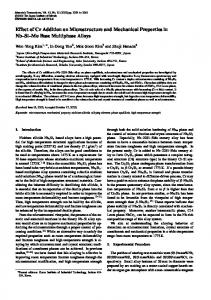
5 Tensile properties 100 mm min21)
of
joints
(welding
Effect of tool rotation rate on microstructure and properties of copper
speed:
seen in the copper welds.11 Actually, whether the TMAZ is distinct or not depends mainly on the welding parameters, what will be discussed in the following. The microstructures of NZ formed at different tool rotation rates are shown in Fig. 2a–c. Compared with the BM (see Fig. 2d), the NZ has much smaller equiaxed grain, smaller than that reported in the references (see Table 1) due to dynamitic recrystallisation and a colder welding condition. With the increase in tool rotation rate, the grains become coarse because high tool rotation rate (welding speed is a constant) results in an increase in both the degree of deformation and the peak temperature of thermal cycle. On the one hand, the increase in the degree of deformation during FSW results in a reduction in the recrystallised grain size to the general principles for recrystallisation.20 On the other hand, the increase in the peak temperature of FSW thermal cycle leads to the remarkable grain growth. Figure 3 shows the microstructure of HAZ obtained at different rotation rates. Compared with the BM (see Fig. 3d), the grains in the HAZ grow to some extent, but the grain size almost does not change with increasing rotation rate from 300 to 800 rev min21 (see Fig. 3a–c). That is to say, the tool rotation rate has little effect on the grain size in the HAZ. The reason for this may be that the heat input is not high and the heat loss is large in the HAZ. Although the heat input increases with increasing rotation rate, the dwelt time at high temperature is short, and thus the grain does not grow further. Figure 4 shows the TMAZ produced at different tool rotation rates. From Fig. 4a and b, it can be seen that there is a distinct boundary between TMAZ and NZ on the advancing side (AS), while the transition between
a front face; b cross-section 6 Fracture locations of joints
TMAZ and NZ is smooth on the retreating side (RS), which can also be observed in Fig. 1. Such a result is dependent on the difference of metal plastic flow state between the two sides in FSW process. On the AS, the flowing direction of plasticised materials in the weld is opposite to that in the BM, and thus resulting in a large relative deformation and a sharp boundary line; while on the RS, the plasticised materials in the weld and in the BM flow in the same direction, therefore the BM deforms together with the weld and the transition is smooth. Comparing Fig. 4 with Figs. 2 and 3, it can be
Table 1 Summary of grain size in NZ of FSW copper Grain size, mm Plate thickness, mm
Rotation rate, rev min21
Welding speed, mm min21
NZ
BM
Reference
5, 15 4 2 5 3
1300 1250 1000 400 400
170 61 30 50 100
70 100 11 9 4
100 210 30 18 25
5 11 12 14 Present
Science and Technology of Welding and Joining
2009
VOL
14
NO
6
580
Shen et al.
Effect of tool rotation rate on microstructure and properties of copper
a low magnitude, b–e magnified of region 1–4 marked in a, it is noted that b–e are in same magnification (tool rotation rate: 300 rev min21) 7 Images (SEM) of tensile fracture surface
seen that the grains in the TMAZ are bigger than that in the NZ, but smaller than that in the HAZ. When the tool rotation rate is low, e.g. 300 rev min21, the TMAZ
is quite narrow and there is a sharp boundary between the TMAZ and NZ (see Fig. 4a). As the tool rotation rate increases, the TMAZ becomes wide and the
Science and Technology of Welding and Joining
2009
VOL
14
NO
6
581
Shen et al.
Effect of tool rotation rate on microstructure and properties of copper
Mechanical properties and fracture locations
a low magnitude; b high magnitude (tool rotation rate: 600 rev min21) 8 Images (SEM) of tensile fracture surface
boundary disappears, and the grain size in the TMAZ increases. The reason for this may result from the heat and mechanical effect.
Figure 5 shows the tensile strength and elongation of the joints welded at different rotation rates. It can be seen that the tensile strength and elongation have the same variation trends. When the tool rotation rate is in a low range, both the tensile strength and the elongation increase with the increase in the tool rotation rate; when the tool rotation rate rises to 400 rev min21, both the joint tensile strength and the elongation reach the highest value, 282 MPa and 16?4% respectively, equivalent to the level of the BM; and when the tool rotation rate increases further, both the tensile strength and elongation decrease, especially when the tool rotation rate is more than 800 rev min21. Figure 6 shows the fracture locations of the joints welded at different tool rotation rates, which can be employed to explain the variation trend of the tensile strength and elongation in Fig. 5. It can be seen that there are some cavities on the AS of the joint produced at the tool rotation rate of 300 rev min21, and thus resulting in a significant decrease in the tensile strength and elongation. The heat input is low and there are no defects in the joint produced at the tool rotation rate of 400 rev min21, so the tensile strength and elongation of the joint are both up to the level of the BM. However, the tensile strength and elongation gradually fall with further increasing the rotation rate and the joint fractures at the RS. The specific fracture position can be obtained from Fig. 6b: the fracture occurs at the cavity defect on the AS of the joint when the tool rotation rate is 300 rev min21; and the fracture path of the joints passes through TMAZ, HAZ and BM on the RS when the tool rotation rate increases to 600 rev min21 and above. In detail, the fracture surface of the joint welded at the tool rotation rate of 300 rev min21 can be divided into four regions, as marked with 1, 2, 3 and 4 in Fig. 7a, and their magnified SEM graphs are shown in Fig. 7b–e respectively. The fracture characteristics and microfracture mechanism are listed in Table 2. It should be noted that copper has a face centred cubic (FCC) lattice structure and usually the cleavage fracture does not occur in the FCC materials, but it may occur in the result of low temperature, eroding surroundings and material defects.21 For the cavity defect occurring on the AS during FSW, the fracture is originated from the cavity defect under the tensile test, and thus the abnormal fracture occurred in the copper joint. Figure 8 shows the fractograph of the joint welded at the tool rotation rates of 600 rev min21. It can be seen that there are many dimples on the fracture surface, indicating a microvoid coalescence mechanism.
Table 2 Fracture characteristics and mechanism of four regions marked in Fig. 7 Fracture characteristics Region
Low magnification
High magnification
Fracture mechanism
1 2 3 4
Tear ridge and snake-like pattern Smooth and regular Tire pattern Tear ridge
Smooth and few flat dimples River pattern Dimples Dimples
Slipping Cleavage Microvoid coalescence Microvoid coalescence
Science and Technology of Welding and Joining
2009
VOL
14
NO
6
582
Shen et al.
Conclusions The FSW of copper was successfully carried out and the following conclusions were drawn from the present investigation. 1. Defect free copper FSW welds were obtained under relatively low heat input conditions. As the tool rotation rates increased, the grains of NZ grew, the boundary between TMAZ and NZ was indistinct and the grain size of TMAZ increased, but the tool rotation rate almost had no effect on the grain size of HAZ. 2. The tensile test showed that the tensile strength and elongation of the joints increased first and then decreased with increasing tool rotation rate. When the tool rotation rate is 400 rev min21 together with a welding speed of 100 mm min21, the ultimate tensile strength achieved a highest value of 282 MPa, equivalent to the level of the BM. 3. The low tool rotation rate resulted in a cavity defect in the weld on the AS, so the fracture occurred at the defect location of the joint, and the microfracture mechanism was involved in slipping, cleavage and microvoid coalescence; and when the tool rotation rate increased, the fracture path of the joint passed through TMAZ, HAZ and BM on the RS, and the fracture surface only showed a microvoid coalescence mechanism.
Acknowledgements The research was sponsored by the National Key Technology Research and Development Programme No. 2006BAF04B09, Ministry of Science and Technology, China, and was supported by the Programme of Excellent Team in Harbin Institute of Technology, China.
References 1. W. M. Thomas, E. D. Nicholas, J. C. Needham, M. G. Murch, P. Temple-Smith and C. J. Dawes: GB patent no. 9125978?8, 1991. 2. C. Dawes and W. Thomas: TWI Bull., 1995, 6, 124–127. 3. C. G. Andersson and R. E. Andrews: ‘Fabrication of containment canisters for nuclear waste by friction stir welding’, Proc. 1st Int. Symp. on ‘Friction stir welding’, Thousand Oaks, CA, USA, June 1999, CD-ROM.
Effect of tool rotation rate on microstructure and properties of copper
4. L. Cederqvist, C. D. Sorensen, A. P. Reynolds and T. Oberg: Sci. Technol. Weld. Join., 2009, 14, 178–184. 5. K. Okamoto, M. Doi, S. Hirano, K. Aota, H. Okamura, Y. Aono and T. C. Ping: ‘Fabrication of backing plate of copper alloy by friction stir welding’, Proc. 3rd Int. Symp. on ‘Friction stir welding’, Kobe, Japan, September 2001, CD-ROM. 6. K. Nakata, S. Inoki, Y. Nagano, T. Hashimoto, S. Johgan and M. Ushio: ‘Friction stir welding of AZ91D thixomolded sheet’, Proc. 3rd Int. Symp. on ‘Friction stir welding’, Kobe, Japan, September 2001, CD-ROM. 7. Z. Loftus, J. Takeshita, A. Reynolds and W. Tang: ‘An overview of friction stir welding Beta 21S titanium’, Proc. 5th Int. Symp. on ‘Friction stir welding’, Metz, France, September 2004, CD-ROM. 8. R. S. Mishra and Z. Y. Ma: Mater. Sci. Eng. R-Rep., 2005, 50, 1– 78. 9. C. G. Andersson, R. E. Andrews, B. G. I. Dance, M. J. Russell, E. J. Olden and R. M. Sanderson: ‘A comparison of copper canister fabrication by the electron beam and friction stir processes’, Proc. 2nd Int. Symp. on ‘Friction stir welding’, Gothenburg, Sweden, June 2000, CD-ROM. 10. R. Nandan, T. DebRoy and H. Bhadeshia: Prog. Mater. Sci., 2008, 53, 980–1023. 11. W. B. Lee and S. B. Jung: Mater. Lett., 2004, 58, 1041–1046. 12. T. Sakthivel and J. Mukhopadhyay: J. Mater. Sci., 2007, 42, 8126– 8129. 13. L. Cederqvist: ‘FSW to seal 50 mm thick copper canisters – a weld that lasts for 100,000 years’, Proc. 5th Int. Symp. on ‘Friction stir welding’, Metz, France, September 2004, CD-ROM. 14. G. M. Xie, Z. Y. Ma and L. Geng: Scr. Mater., 2007, 57, 73–76. 15. H. J. Liu, H. Fujii, M. Maeda and K. Nogi: J. Mater. Process. Technol., 2003, 142, 692–696. 16. J. C. Feng, D. Y. Wang, G. Q. Chen and H. J. Liu: ‘The effect of welding speed on mechanical properties and microstructures of friction stir welded joint of AI-Li alloy’, Proc. 1st Int. Conf. on ‘New forming technology’, Harbin, China, September 2004, 555– 560. 17. L. M. Marzoli, R. Zettler, J. F. dos Santos, M. Volpone and E. Rizzuto: ‘A preliminary investigation on the microstructure and properties of friction stir welds in an Al7075/Al2O3/10% reinforced alloy’, Friction Stir Welding Processing III, San Francisco, CA, USA, February 2005, 243–251. 18. H. J. Liu, Y. C. Chen and J. C. Feng: Mater. Sci. Technol., 2006, 22, 237–241. 19. H. Lombard, D. G. Hattingh, A. Steuwer and M. N. James: ‘Optimising FSW process parameters to minimise defects and maximise fatigue life in 5083-H321 aluminium alloy’, Proc. Int. Conf. on ‘Crack paths’, Parma, Italy, September 2006, 341– 354. 20. F. Humphreys and M. Hatherly: ‘Recrystallization and related annealing phenomena’, 221–232; 2004, New York, NY, Pergamon Press. 21. Y. X. Cui, C. L. Wang and M. Yao: ‘Fracture analysis of metals’, 52; 1998, Harbin, Harbin Institute of Technology Press.
Science and Technology of Welding and Joining
2009
VOL
14
NO
6
583