The output voltage of a variable frequency drive (VFD) is not the sinusoidal wave
that is normally expected from a utility connection. Figure 1 shows the voltage ...
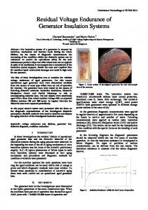
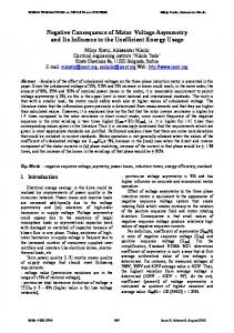
Power Quality Effect of Variable-Frequency Drive Output Voltage on Motor Insulation Background The output voltage of a variable frequency drive (VFD) is not the sinusoidal wave that is normally expected from a utility connection. Figure 1 shows the voltage applied to the motor from the drive, consisting of pulses with a rise time (the time between 10% and 90% of maximum value) that can be as short as 50 ns for modern drives using insulated gate bi-polar transistors (IGBT) in their inverter stage. Consequently, motors connected to VFDs will be subjected to repetitive voltage pulses that under certain circumstances can be magnified when they reach the motor terminals. Figure 2 shows such a magnification where the VFD output voltage pulse, as it appears at the terminals of a 460-V motor, is approximately 1200 V, in contrast with the 620 V to 660 V level expected in the absence of magnification.
Figure 1 – Typical voltage output waveform of a variable-frequency drive The industry workhorses, low-voltage induction motors, are designed to withstand 600 V rms under sinusoidal excitation. When the same motor is now connected to VFDs, the motor insulation can be subjected to a repetitive stress from voltage pulses that can be much higher than the peak of 600 V rms and consequently degrade the insulation system. If proper action is not taken, then under the worst case condition, turn-to-turn insulation failure in the motor can happen in a short time. Even if such failure does not happen in a short time, these pulses will ultimately degrade the insulation system and reduce the expected life of the motor. The purpose of this tech note is not to present a theoretical background on why and how this phenomenon occurs, but to provide guidance for users of VFDs in order to avoid this situation when a VFD is retrofitted to an existing motor, or in a new application.
1
Figure 2 – Voltage magnification at the motor terminals
Conditions for Voltage Magnification The length of the cable connecting the VFD to the motor, the rise time of the VFD output voltage pulse and the size of the motor are the main variables affecting how much voltage magnification will occur at the motor terminals. The longer the cable length, the shorter the rise time, and the smaller the motor, the greater risk of damage to the motor insulation. Figure 3 shows, as a function of rise time, the cable length beyond which voltage doubling occurs at the motor terminals. The type of insulation system used in a specific motor, to a large degree, determines how the voltage pulse will affect the motor. Many standard fractional horsepower motors are wound without using any supplementary phase insulation. They are also coated with a very thin film of varnish covering. These motors are particularly susceptible to insulation damage under VFD operation. Field experience indicates that the majority of premature failures of motors under VFD operation were motors rated under 25 hp.
Figure 3 – Cable length beyond which voltage doubling occurs, as a function of rise time
2
Recommendation for Retrofit Application In many cases, VFDs are good candidates for an existing application such as air handling units in building HVAC (Heating Ventilation and Air Conditioning) systems. The cost/benefit analysis for such an application often dictates that the exiting motors be used with VFDs. Based on the risk factors explained above (long cable, short rise time, small motor), the use of existing motors should be carefully evaluated and the use of filters at the output of the VFD should be considered. Motors should be inspected to ascertain that phase insulation and proper varnish coating exist between turns. If there is an alternative choice, then VFDs having a rise time of at least 0.5 ms should be chosen and the switching frequency for VFDs should be selected below 5 kHz. There are basically three different types of commercially available filter networks for reducing the overvoltages at the motor terminals. These filters are typically installed at the output of the VFD. Line reactors (inductors), resistor-capacitor (R-C) snubbers, and R-L-C low-pass filters are commonly used to reduce the voltage at the motor terminals. In the majority of cases, the R-L-C low-pass filter has been found to be the most effective filter. However, the user should consult the VFD vendor to select the filter that will match the specific VFD that is selected for the application. Whatever type of filter is installed, the user should always determine the voltage at the motor terminals during start-up of the installation, using a proper measurement device to assess the effectiveness of the filter. If the user believes that the risk factor does not justify using filters, then a similar measurement should be done to ascertain that voltage magnification is not occurring. Measurement of motor terminal voltage Measuring the peak overvoltage at the motor terminals should be a requirement for the user. Care must be exercised in using the right type of instrument. Typical analog or digital voltmeters cannot properly measure the peak voltage since the duration of these pulses is in hundreds of nanoseconds and most of the voltmeters that are available on the market will not be able to properly detect the peak voltage. A high-speed oscilloscope is best for the purpose; some hand-held oscilloscopes that are available at a relatively low cost compared to their laboratory counterparts would be adequate for this kind of measurement. The trigger level of the oscilloscope should be first set at 2500 V and a 5-10 us/div time base should be selected. Then, the trigger threshold is gradually lowered until the scope triggers for the first time. This procedure will ensure that the peak voltage at the motor terminals is properly captured.
‘Inverter Duty’ Motors For new applications of VFDs and motors, users should consider using an Inverter-Rated motor. The National Electrical Manufacturers Association (NEMA) has developed the NEMA-MG Part 31 Standard that defines the requirements for motors used with VFDs. These motors are designed so that their insulation system can withstand 1600 V pulses with a rise time longer than 0.1 ms. However, in many cases, the designation of ‘Inverter-Rated’ might not necessarily mean that the motor complies with the NEMA Standard. For older type, six-pulse VFDs, the main concern for motors was additional heating caused by the harmonic content of the motor current; manufacturers would oversize the motor, provide additional ventilation capability and designate the motor as ‘Inverter-Rated Motor’. However, with the present-day IGBT technology, the concern is no longer overheating, it is insulation degradation. Users should explicitly request the motor manufacturer to comply with NEMA MG-Part 31. The motor manufacturer must provide information to the buyer regarding which one (or more) of the following key features have been added to augment the motor insulation system to enhance the insulation system of the motor: •
magnet wire with increased dielectric strength;
•
improved insulation on end turns, in the slots, and between phases;
•
heavy-duty lacing or taping of end-turns;
•
additional cycles of varnish dip or vacuum-pressure impregnated; 3
•
maximized copper content;
•
high-temperature insulation with low thermal rise levels.
Use of 230 V / 460 V Motors Many motors are designed for operation from either a 230 V or a 460 V supply. In such cases, 230 V VFDs and motors rated 230 V / 460 V will solve the problem. This is because the insulation systems for dual-wound motors are designed for 600 V rms operation; when 230 V is used, then even if voltage magnification occurs at the motor terminals, the peak voltage is still below the insulation withstand capability of the motor. This is a viable option for many small fractional horsepower motors that have the provision for either 460 V or 230 V operation.
Summary The new generation of variable frequency drives requires some simple precautions to avoid premature failure associated with the nature of the output voltage of these drives. These precautions are especially important in the case of a retrofit using an existing motor, but should also be observed for new applications: •
On existing systems, verify that voltage magnification does not occur by making a measurement at the motor terminals, with a suitable instrument;
•
For a proposed new system, ascertain that the combination of cable length and rise time will not result in voltage magnification;
•
If voltage magnification is found on an existing system or anticipated for a new system, consider the insertion of an appropriate filter, or select a drive with rise time of at least 0.5 µs.
•
Consult the drive vendor and ascertain that the characteristics of the drive and the capability of the motor (existing or proposed) are compatible in the context of the voltage magnification concerns.
December 1997
4