Journal of
Journal of Mechanical Science and Technology 23 (2009) 1693~1701
Mechanical Science and Technology
www.springerlink.com/content/1738-494x
DOI 10.1007/s12206-009-0414-4
Effect of wave conditions on the performance and internal flow of a direct drive turbine† Young-Do Choi1, Chang-Goo Kim2 and Young-Ho Lee3,* 1
School of Mechatronics, Changwon National University, Changwon, 641-773 Korea Department of Mechanical Engineering, Graduate School, Korea Maritime University, Busan, 606-791 Korea 3 Division of Mechanical and Information Engineering, Korea Maritime University, Busan, 606-791 Korea
2
(Manuscript Received August 13, 2008; Revised March 11, 2009; Accepted March 30, 2009) --------------------------------------------------------------------------------------------------------------------------------------------------------------------------------------------------------------------------------------------------------
Abstract The purpose of the present study is to investigate the effect of wave conditions on the performance and internal flow of a newly developed direct drive turbine (DDT) model for wave energy conversion experimentally. All the experiments using the test turbine models are conducted in a 2-D wave channel. Monochromatic waves of various conditions of wave height and wave period are applied to the turbine performance test. The influences of turbine configuration on turbine performance are also investigated. Test results show that rotational speed, differential pressure, incident flow rate, maximum output power, and best efficiency of the turbine model vary considerably depending on the wave conditions. Installation of a front guide nozzle and a rear water reservoir to the test turbine improves the turbine performance. Large passage vortex occurs both at the front and rear turbine nozzles in turn through a reciprocating flow in the turbine passage. Keywords: Wave energy conversion; Direct drive turbine; Wave condition; Performance; Internal flow --------------------------------------------------------------------------------------------------------------------------------------------------------------------------------------------------------------------------------------------------------
1. Introduction Wave energy converters are usually classified as either a fixed type or a floating type. The converters are further grouped as hydraulic, pneumatic, or rotating. As a representative wave energy converter, oscillating water column (OWC) type turbines, such as Wells and impulse turbines, use compressed air as a working fluid; thus, the turbine is a kind of pneumatic wave energy converter [1-3]. It uses the rise and fall of waves to create an oscillating flow of air, which in turn drives a bi-directional flow turbine. However, turbines that use the oscillating flow of air have problems such as a relatively large rotational speed variation and high air noise coming from the runner pas†This paper was recommended for publication in revised form by Associate Editor Jun Sang Park * Corresponding author. Tel.: +82 51 410 4293, Fax.: +82 51 403 0381 E-mail address:
[email protected] © KSME & Springer 2009
sage, in comparison with those of the hydro turbine which uses water as a working fluid. To address these problems, Fukutomi et al. [4] and Choi et al. [5, 6] have proposed a direct drive turbine (DDT). The DDT uses water as working fluid, thus a greater amount of output power is expected in comparison with that of the OWC type turbine because, generally, water as the working fluid has about 1000 times the energy density of air. The turbine is designed to maintain a unidirectional runner rotation though the reciprocating flow converted from the wave movement. As the DDT will be installed and operated at offshore sites, the effect of wave conditions on the turbine performance and internal flow should be examined in detail. Hence, the present experiment has been conducted in a 2-D wave channel in order to apply the wave conditions to the incident flow of the DDT. Moreover, the effects of several passage combinations by the turbine front and rear nozzles, as well as
1694
Y.-D. Choi et al. / Journal of Mechanical Science and Technology 23 (2009) 1693~1701
the attached devices, which are adopted for the improvement of the turbine performance, are investigated experimentally. The particle image velocimetry (PIV) measurement technique is adopted for a detailed visualization of the turbine internal flow.
Rear water reservoir Wave gauge 250
2.1 Experimental setup Fig. 1 shows the schematic view of the experimental apparatus adopted in this study. All the experiments for the test turbine model are carried out in a 2D wave channel. The wave channel has a total length of 35m, a width of 1m, and a depth of 1m. The bottom slope of the wave channel consists of a 7m flat section at the deep end from a wave maker, and a slope of 1:100 at the shallow end. The test turbine model is installed at a position 15m downstream of the wave maker in the wave channel. A piston-type wave maker in the wave channel can generate monochromatic waves with various wave heights and wave periods. The wave condition can be controlled by the displacement and velocity of wave paddle movements. A torque meter is installed outside the turbine and the output torque generated at the runner shaft is transferred to the torque meter by a pulley installed at the runner shaft and the timing belt. The rotational speed of the test runner is measured using a revolution counter attached to the torque meter. An air tension brake is used to control the runner’s rotational speed. Two pressure transducers are connected to the holes on the sidewalls both at the front and rear turbine nozzles to measure the differential pressure between the turbine nozzles. Two capacitance wave gauges are installed in the water channel at distances of 3,650mm upstream and 550mm downstream of the test turbine center. The wave data measured by the wave gauge at the position upstream of the turbine guide nozzle is used to examine the incident wave condition, but the wave data measured at the rear water reservoir is used to calculate the incident flow rate by averaging the time serial wave height in the reservoir. A 3-D acoustic doppler velocimeter (ADV) is installed at the center passage of the turbine front nozzle in order to measure the time serial consecutive instantaneous 3-D velocity components in the nozzle passage. All the digital signal measurements of the test equipment are transferred to a data logger and the measurement data are treated and saved in the data
Unit : mm
Front guide nozzle Rear nozzle
hT L 175
2. Test turbine and experimental apparatus
Wave gauge
3-D acoustic doppler velocimeter
Torque meter
Front nozzle
750
3650
Fig. 1. Schematic view of experimental apparatus when the test turbine 1 is installed in a 2-D wave channel.
logger synchronously. The sampling interval of all kinds of data acquisition is determined up to 20ms. The uncertainty estimates for each variable in the graphs are based on the method of Abernethy et al. [7]. The total uncertainty ( U ) of the variables can be derived by combining systematic and random errors as : U = [ B 2 + (tS X ) 2 ]1/ 2 , where B is the systematic uncertainty, S X is the standard deviation of the mean, and the degree of freedom t is determined to have a value of 2 for a 95% confidence level (for a sample size greater than 50). The systematic uncertainty B is estimated based on the calibration data and previous test experience, and the standard deviation of the mean S X is computed from the raw test data. Measurement uncertainties for turbine performance under a loaded condition are estimated to be Q = ± 1.39 percent, ∆H = ± 1.0 percent, T = ± 1.4, PT = ± 1.5 percent and η = ± 2.23 percent at the rotational speed of best efficiency, respectively. 2.2 Test turbine and runner The cross-sectional image of the test DDT model and the descriptions of the turbine parts are indicated in Fig. 1. The detailed design concept and operating mechanism of the turbine are described in the paper by Lee et al. [8]. Three kinds of test turbine models are adopted in this study, and the dimensions of the turbine models are summarized in Table 1. The crosssectional configurations of the test turbine models are the same but the sizes of the turbine models are determined differently according to the experimental purposes of this study. Turbine 1 is used to examine turbine performance under various wave conditions. Turbine 2 is adopted to investigate the effect of the front guide nozzle and the rear water reservoir on turbine performance. For the examination of the influence of the attachment devices, the front guide nozzle, and the rear water
1695
Y.-D. Choi et al. / Journal of Mechanical Science and Technology 23 (2009) 1693~1701
Table 1. Dimensions of the test turbine models. Turbine Cross-sectional area at the front and rear nozzle inlets A (hT × b) [mm × mm] Length L [mm]
Table 4. Dimensions of the test runner.
1
2
3
250 × 700
190 × 700
125 × 700
700
540
350
Table 2. Test cases for the influence of the attachment devices on turbine performance. Test
Front guide nozzle
Rear water reservoir
Case 1
Attached
Attached
Case 2
Attached
None
Case 3
None
Attached
Case 4
None
None
Runner Outer Diameter [mm] Diameter ratio Outer blade angle [deg.] Inner blade angle [deg.] Blade number
D2
1
2
3
260
200
130
D1/D2
0.644
α
30
β
90
Z
30
Table 3. Test cases for the influence of the combined configurations of turbine nozzles with attachment devices.
Case I
Turbine direction Normal
Front guide nozzle Attached
Rear water reservoir Attached
Test
Case II
Reverse
Attached
Attached
Case III
Normal
None
None
Case IV
Reverse
None
None
reservoir are designed separate from the main frame of the turbine model. The role of the front guide nozzle is to gather the wave energy efficiently and to change the rise and fall of the wave movements to reciprocate the flow at the turbine inlet. Table 2 shows the test cases for the influence of the attachment devices on turbine performance. Moreover, Turbine 2 is also used to examine the influence of the combined configurations of turbine nozzles with the attachment devices on turbine performance. Some test cases on the combinations of the turbine nozzle inlets with the attachment devices are determined as shown in Table 3. As the configuration of the turbine nozzle is axisymmetric, the test cases are determined by the relative turbine direction in relation to the attachment devices such as the front guide nozzle and rear water reservoir. Turbine 3 is adopted for the internal flow visualization of the turbine model passage. Fig. 2 and Table 4 show the image of the test runner and its dimensions, respectively. The sizes of the test runners are suited for each test turbine model size. The runner blade and sidewall of the test runner for
Fig. 2. Image of the test runner.
Turbine 3 are made of transparent acrylic resin for visibility inside the turbine internal passage. This way, the PIV measurement can be conducted. Moreover, the reason for the selection of runners is their adequacy. Since the turbine for the wave power conversion is naturally determined by its relatively low head and fast flow rate in comparison with that of the hydro turbine on land, the cross flow type runner is adequate for the large value of the flow rate and relatively low rotational speed. 2.3 PIV measurement system for internal flow visualization For the visualization of the internal flow in the nozzle passage of the test turbine model, the Particle Image Velocimetry (PIV) system is adopted. Fig. 3 shows the image of the two-dimensional PIV measurement system. A high speed camera (Resolution of 1Kx1K pixel) takes consecutive images on the center plane of the nozzle passage from the direction perpendicular to the plane of light sheet. A continuous laser sheet (542nm, Ar-Ion laser, 500mW) are used as a source of illumination for the PIV measurement. The light sheet is aligned from the upper side of the test turbine model. It is likewise illuminated through transparent windows installed on the upper side of the front and rear turbine nozzles. The thickness of the light sheet is fixed at 0.5mm at each measured plane. The time interval of two consecutive images is set to
1696
Y.-D. Choi et al. / Journal of Mechanical Science and Technology 23 (2009) 1693~1701
Ar-Ion laser head
Wave DDT
Front guide nozzle High speed camera
(a) No load condition Fig. 3. Experimental setup for the visualization of the DDT internal flow by PIV (Turbine 3).
2ms with consideration for a maximum fluid velocity at the nozzle passages. A vinyl chloride polymer (diameter about 100µm; specific gravity, 1.1) is used as a tracer particle. A cross-correlation PIV algorithm [9] is used as a particle-tracking method. As a calibration method for the PIV measurements, the method of Raffel et al. [9] is used.
3. Results and Discussions 3.1 Time serial output data Fig. 4 shows the time serial output data measured from Turbine 1 under both cases of no load and loaded conditions. It is clear that the rotational speed of the runner varies regularly according to the incident reciprocating flow conditions caused by wave movements. The variation of the instantaneous turbine output power PT instant and torque T instant is periodic and the two components have a close relationship with each other. The periodic variation of the instantaneous effective head H instant, which is calculated from the differential pressure between the front and rear nozzles (∆Hinstant =∆pinstant /ρg), is also synchronized with the instantaneous flow rate, Qinstant, by the reciprocating flow in the turbine passage. In the test under loaded condition, the instantaneous output power and the torque increase simultaneously in comparison with the no load condition. The load is controlled by an air tension brake by controlling the rotational speed of the runner axis. According to the present experimental result, the instantaneous effective head under the loaded condition becomes larger in comparison with that of the no load condition because flow resistance to the test runner increases in the turbine passage when the load is applied to the runner axis. Consequently, the instantane-
(b) Loaded condition Fig. 4. Time serial output data (Turbine 1, Tp=2.0 sec., H=20 cm, h=75 cm).
ous differential pressure between the front and rear turbine nozzles increases and, thus, the instantaneous output torque becomes larger at a fixed load. 3.2 Turbine performance by wave condition Figs. 5 and 6 reveal turbine performance according to the variations of wave height and wave period under the no load condition. In the case of wave height variation, the factors of flow rate Q passing through the turbine passage, static pressure pf at the front nozzle, and rotational speed n increase considerably almost in proportion to the increase of wave height as shown in Fig. 5. When the wave height is relatively low in the case of the wave period variation, flow rate and static pressure show no relationship with the variation of the wave period in the range below Tp =1.9 sec. as shown in Fig. 6. However, the rotational speed increases gradually in the range of the wave height H ≥ 15 cm according to the increase of the wave period. When the period is Tp =2.0 sec., all the output factors increase remarkably. This result implies that there is a wave period threshold value for the improvement of turbine performance.
Y.-D. Choi et al. / Journal of Mechanical Science and Technology 23 (2009) 1693~1701
1697
(a) Wave height H=20 cm Fig. 5. Effect of wave height on the turbine performance (Turbine 1, no load condition, h=75 cm).
(b) Wave height H=26 cm Fig. 7. Performance of the test turbine model by wave height (Turbine 1, Tp=2.0 sec., h=70 cm). Fig. 6. Effect of wave period on the turbine performance (Turbine 1, no load condition, h=75 cm).
3.3 Performance curves by the wave height Fig. 7 shows the performance curves of the test turbine model by wave height under a loaded condition. The torque decreases almost linearly with the increase of the rotational speed in both cases of wave height variation as shown in Figs. 7(a) and 7(b). However, the effective head and flow rate changes slightly with the increase of rotational speed. In the cases of output torque and efficiency of the turbine model by the rotational speed variation, the changes are remarkable. When the wave height increases, the efficiency and output power increase considerably. Moreover, when the performance curves in Figs. 7(a) and 7(b) are compared with each other, the rotational speed at the best efficiency point moves to the high rotational speed range with the increase of the wave height. The turbine best efficiency at the relatively higher wave height of H=26cm in Fig. 7(b) shows an appreciable efficiency of ηbep=51.6%, which is a consider
able value when comparing the general turbine efficiency of OWC-type turbines [1-3]. Therefore, this result shows the good application possibility of the present DDT in the wave energy converter system. 3.4 Turbine performance by turbine passage configuration to the incident wave Fig. 8 shows the influence of the attachment devices installed at the turbine front and rear nozzle inlets on the turbine performance under the no load condition. When the front guide nozzle and rear water reservoir attachment devices are installed to both the front and rear nozzle inlets (Case 1), the rotational speed and effective head reveals maximum values among the cases. In this study, the effective head ∆H plays a very important role for the incident water power Pw because water power is proportional to the effective head (Pw=ρgQ∆H). If the effective head becomes larger, the water power is increased. Thus, when the turbine efficiency is fixed (PT=Pwη), the output power of the turbine can be increased. When the attachment devices are taken away from
1698
Y.-D. Choi et al. / Journal of Mechanical Science and Technology 23 (2009) 1693~1701
the front and rear nozzle inlets the turbine performance decreases accordingly. According to these results from the combination of the turbine main frame and the attachment devices, the influence of front guide nozzle and rear water reservoir on the turbine performance is clearly considerable. Moreover, it is clear that the effect of the front guide nozzle is larger than that of the rear water reservoir on turbine performance. In order to examine the influence of the combined configurations of the turbine front and rear nozzles with the attachment devices on turbine performance, some cases are tested as shown in Fig. 9. When the front guide nozzle and rear water reservoir are installed at the turbine main frame as shown in Fig. 10 (Case I), the rotational speed almost does not change in comparison with the result of the case of reverse turbine direction (Case II). However, the effective head responds significantly to the combined configurations of the turbine passage. Therefore, it is conjectured that the relatively high effective head of Case II compared with that of Case I results from the influence of the passage shape from the inlet of the front guide nozzle to the outlet of the turbine nozzle. As shown in Fig. 10, Case II has a relatively smooth change of flow passage configuration in comparison with that of Case I, thus, the hydraulic loss of Case II becomes smaller than that of Case I. Furthermore, when there is no attachment device to the test turbine, the normal direction of the turbine main body in relation to the incident flow (Case III) shows better effective head than the case of the reverse installation (Case IV). Therefore, the result implies that the optimum nozzle combination of the turbine front and rear nozzles and the attachment devices is very important. Moreover, optimum nozzle shape should be carefully considered for further improvement of turbine performance.
Fig. 8. Influence of attachment devices on the turbine performance (Turbine 2, no load condition, Tp=2.0 sec., H=20 cm, h=70 cm).
Fig. 9. Influence of nozzle configuration on the turbine performance (Turbine 2, no load condition, Tp=2.0 sec., H=20 cm, h=70 cm).
(a) CaseⅠ
(b) Case Ⅱ
Fig. 10. Flow patterns in the flow passage at the inlet of DDT by the combined configuration of turbine front and rear nozzles with attachment devices.
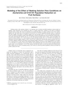
3.5 Internal flow in the nozzle passages Fig. 11 shows the internal flow image on the center plane of the front nozzle passage in the case of incident flow from the front guide nozzle. The flow direction changes periodically due to the reciprocating flow in the turbine passage. A 3-D velocimeter sensor is shown at the inlet in the front nozzle passage. Fig. 12 shows the time serial instantaneous 3-D velocity components in the turbine front nozzle meas-
Fig. 11. Internal flow image on the center plane of the turbine front nozzle (Turbine 3).
1699
Y.-D. Choi et al. / Journal of Mechanical Science and Technology 23 (2009) 1693~1701 Front nozzle
Runner Flow
Vortex Vortex Rear nozzle
(a) Inflow from the front nozzle inlet Front nozzle Vortex
Fig. 12. Time serial instant 3-D velocity components in the turbine front nozzle measured by 3-D ADV (Turbine 3, Tp=2.0 sec., H=20 cm, h=70 cm).
ured by the velocimeter sensor. Relatively higher velocity fluctuations are found in the x-direction velocity component among the velocity components. The x-direction velocity component corresponds to the horizontal reciprocating flow velocity in the turbine nozzle. Due to the influence of the passage shape of the front guide nozzle, a considerable amount of zdirection velocity fluctuation below zero, which corresponds to the vertical velocity fluctuation to the direction of wave channel bottom, exists in the flow field. Fig. 13 shows instantaneous velocity vectors measured in the nozzle passages by the PIV measurement technique. The PIV measurement is carried out simultaneously with the measurement of the velocity in the turbine front nozzle inlet by the 3-D velocimeter. When an incident flow enters the turbine front nozzle located at the right side of the test runner, as shown in Fig. 13 (a), the flow velocity at the front nozzle passage increases at the relatively narrow nozzle region just before the runner inlet. The turbine nozzle inlet velocity measured by PIV shows quantitatively good agreement with the velocity components measured by the 3-D acoustic doppler velocimeter even though the velocity components measured the by 3-D velocimenter fluctuate with time. This is shown in Fig. 12. Moreover, there exists a large vortex in the rear nozzle passages. When the flow direction changes to the revere as shown in Fig. 13 (b), the flow pattern likewise reverses its direction. The results suggest that the reciprocating flow passing through the axisymmetric nozzle passage is influenced remarkably by the nozzle shape. The velocity distribution in the nozzle passage and vortex forma-
Runner
Flow
Rear nozzle
(b) Inflow from the rear nozzle inlet Fig. 13. Instant velocity vectors measured by PIV in a DDT nozzle passage (Turbine 3, Tp=2.0 sec., H=20 cm, h=70 cm).
tion has a close relationship with the nozzle shape.
4. Conclusions (1) A direct drive turbine (DDT) for wave energy conversion shows good performance under the various input wave conditions. A relatively high turbine best efficiency of ηbep=51.6% under a wave condition reveals its good application possibility in the wave energy conversion system. (2) The effect of wave height on the performance of the present DDT is considerable and the turbine performance shows an almost equal proportion to the wave height. In particular, the static pressure at the turbine front nozzle and incident flow rate increase proportionally with the increase of wave height. (3) The wave period gives a relatively small effect on turbine performance under a small value of the wave period. However, there exists an optimum wave period of a threshold value which considerably improved the turbine performance against the threshold value of the wave period. (4) The shape of the front guide nozzle, which is attached to the inlet of the turbine front nozzle, has a considerable effect on the turbine performance. Therefore, the optimum nozzle configuration, combined with the turbine front and rear nozzles and the
1700
Y.-D. Choi et al. / Journal of Mechanical Science and Technology 23 (2009) 1693~1701
attachment devices, is very important for the improvement of turbine performance. Moreover, the optimum nozzle shape should be carefully considered for further improvement of turbine performance. (5) Internal flow patterns visualized by PIV reveal that there exists a large vortex in the turbine nozzle passage. The flow pattern largely changes the flow direction caused by the reciprocating flow in the turbine passage.
Nomenclature----------------------------------------------------------A b D1 D2 g H HT ∆H ∆H instant h hT L
: : : : : : : : : : : :
n PT PT instant Pw pf
: : : : :
∆p
:
Q Qinstant T Tinstant Tp Z
: : : : : :
Nozzle inlet cross-sectional area Width of nozzle and test runner Inner diameter of test runner Outer diameter of test runner Acceleration of gravity Wave height Height of the turbine nozzle inlet Effective head Instantaneous effective head Water depth Height of turbine nozzle inlet Turbine length from the front to the rear edges Rotational speed Output power Instantaneous output power Water power Static pressure at the side wall of the front nozzle Differential pressure between the turbine front and rear nozzles Volumetric flow rate Instantaneous flow rate Output torque Instantaneous output torque Wave period Number of runner blades
Greek symbols
α β η
: Runner outer blade angle : Runner inner blade angle : Turbine efficiency (=PT/ρgQ∆H)
ηbep ρ
: Turbine efficiency at the best efficiency point : Density of working fluid
References [1] Research and Development of Wave Energy Utilization Technology - Development of Offshore Floating Type Wave Energy Converter Mighty Whale, JAMSTEC (in Japanese), Japan, (2004). [2] T. Setoguchi, S. Santhakumar, M. Takao, T. H. Kim and K. Kaneko, A Performance study of a radial turbine for wave energy conversion, Proc. Instn Mech Engrs Part A : Power and Energy 216 (1) (2002) 15-22. [3] R. Curran, Productivity of Ocean-Wave Energy Converters: Turbine Design, J. Energy Engineering 128 (2) (2002) 13-31. [4] J. Fukutomi and Y. Nakase, A Study of turbine for wave power generation, Proc. of the 1st Pacific / Asia Offshore Mechanics Symposium, Seoul, Korea, (1990) 193-198. [5] Y.-D. Choi, C.-G. Kim, Y.-J. Cho, Y.-T. Kim and Y.-H. Lee, Internal Flow Characteristics of CrossFlow Hydraulic Turbine for Wave Power System, Proc. of the 9th AICFM, Jeju, Korea (2007) CDROM Paper No. : AICFM9-296. [6] Y.-D. Choi, C.-G. Kim, Y.-T. Kim and Y.-H. Lee, A Study on the Nozzle Shape of a Cross-Flow Type Hydro Turbine for Wave Power Generation, J. of Fluid Machinery (in Korean) 11 (3) (2008) 30-35. [7] R. B. Abernethy, R. P. Benedict and R. B. Dowdell, ASME Measurement Uncertainty, ASME J. Fluids Eng. 107 (1985) 161-164. [8] Y.-H. Lee, Y.-D. Choi, C.-G. Kim and Y.-C. Hwang, Performance of a Direct Drive Hydro Turbine for Wave Power Generation System, Proc. of 24th IAHR Symposium on Hydraulic Machinery and Systems, Foz do Iguassu, Brazil (2008) CDROM Paper No. : IAHR-321. [9] M. Raffel, C. Willert and J. Kompenhans, Particle Image Velocimetry-A Practical Guide, SpringerVerlag, New York (1998) 105-146.
Y.-D. Choi et al. / Journal of Mechanical Science and Technology 23 (2009) 1693~1701
Young-Do Choi received his B.E. and M.E. degrees in Mechanical Engineering from Korea Maritime University, Korea in 1996 and 1998, respectively. He received his Ph.D. in Engineering from the Yokohama National University, Japan in 2003. Dr. Choi is currently a research professor at the School of Mechatronics, Chanwon National University in Changwon, Korea. His research interests include ocean energy, wind power, small hydro power, fluid machinery, PIV and CFD. Chang-Goo Kim received his B.E. and M.E. degrees in Mechanical Engineering from Korea Maritime University, Korea in 2007 and 2009, respectively. Mr. Kim is currently a doctorate student in the Department of Mechanical Engineering, Graduate School, Korea Maritime University. His research interest includes ocean energy.
1701
Young-Ho Lee received his B.E. and M.E. degrees from Korea Maritime University, Korea. He received his Ph.D. in Engineering from the University of Tokyo, Japan. Dr. Lee is currently a Professor at the Division of Mechanical and Information Engineering, Korea Maritime University. His research interests include ocean energy, wind energy, small hydro power, fluid machinery, PIV, and CFD.