The 7
th
International Conference on FRP Composites in Civil Engineering International Institute for FRP in Construction
EFFECT OF WEB REINFORCEMENT IN FRP-REINFORCED DEEP BEAMS Khaled MOHAMED Ph.D. Candidate, University of Sherbrooke, Canada
[email protected]
Ahmed Sabry FARGHALY Post-Doctoral fellow, University of Sherbrooke, Canada
[email protected]
Brahim BENMOKRANE Professor, University of Sherbrooke, Canada
[email protected]
ABSTRACT: This paper investigates the behavior of four full-scale GFRP-reinforced concrete deep beams with and without web reinforcement. The deep beams were 5000 mm long with the same crosssection of 1200 mm in height and 300 mm in width. The deep beams were tested under two-point loading over a 3000 mm span with the same shear span of 1250 mm. Three different configuration of web reinforcement for three beams were used; with horizontal web reinforcement only, with vertical web reinforcement only, and with horizontal and vertical web reinforcement. The fourth beam was without web reinforcement. The behavior of the deep beams was described in terms of cracking patterns and modes of failure, load-deflection response, ultimate shear strengths, and strains in longitudinal reinforcement. The test results indicated that web reinforcement significantly controlled the crack widths.
1. Introduction Reinforced concrete deep beam defined as a structural member having a relatively small shear span-todepth ratio (a/d) such that the dominant behavior is shear deformations. In deep beams plane sections do not remain plane and, in addition, unlike slender beams, a significant amount of load is transferred to the support by a compression strut joining the loading point and the support. It has various structural applications such as transfer girders in reinforced concrete bridges. RC bridges in northern climate are exposed to corrosion problem due to the use of de-icing salts. In order to avoid the problems created by the corrosion of steel reinforcement, research has demonstrated that one could replace the steel reinforcement by fiber-reinforced-polymer (FRP) reinforcement. The direct replacement of steel with FRP bars, however, is not possible due to various differences in the mechanical properties of the FRP materials compared to steel. Therefore, few researchers conducted experimental investigations to study the behavior of FRP-reinforced concrete deep beams with different types of FRP bars (Farghaly and Benmokrane 2013) and different a/d ratio (Andermatt and Lubell 2013). The previous research, however, focused only on FRP-reinforced deep beams without web reinforcement. For steel-reinforced deep beams, experimental observations showed that web reinforcement improves the strength of the inclined strut and, hence, the shear strength of deep beams. In addition, it reduces the instability failures due to the out-of-plane actions related to the heterogeneous nature of concrete. Furthermore, a clear significant effect; on both crack control and shear strength, was observed by having web reinforcement (Birrcher et al. 2013). The previous study by Farghaly and Benmokrane (2013) pointed out that the increase in reinforcement ratio of the main longitudinal reinforcement in FRP-reinforced deep beams significantly controlled the crack width and increased the ultimate load capacity as well, even without providing web reinforcement. Therefore, it is expected that providing web reinforcement for FRP-reinforced deep beams might have significant effect on crack control and the ultimate load capacity. The present investigation seeks to supplement such information since the effect of vertical and horizontal web reinforcements on the behavior of steel reinforced concrete deep beams has already been shown to be significant.
Page 1 of 6
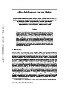
2. Experimental Program The experimental program consists of four full-scale deep beams with constant rectangular cross-section, 1200 mm in height and 300 mm in width. All deep beams were tested under two-point loading with the same span of 3000 mm and a shear span of 1250 mm resulting in a/d ratio of 1.13 with a total length of 5000 mm. The details of the test specimens are shown in Fig. 1-a. All specimens reinforced with eight GFRP-longitudinal-bars having a diameter of 25.4 mm. Three specimens reinforced horizontally and/or vertically with GFRP bars, while the fourth one remained without web reinforcement as shown in Fig. 1-b. The amounts of web reinforcement were calculated to satisfy the requirement of ACI 318 (2011) and CSA S806 (2012) in terms of reinforcement ratio and spacing between bars. Steel stirrups of 8 mm diameter with 100 mm spacing were provided at the over-hanging section beyond the support to prevent the concrete cover splitting close to the GFRP bars.
Vertical RFT only Horizontal RFT only
(a)
(b)
Fig. 1 – Specimens geometry and cross-section
Table 1 – Details of tested specimens. Vertical reinforcement Horizontal reinforcement Bar size Spacing Bar size Spacing ρv % ρh % (mm) (mm) (mm) (mm) G8-8 1.13 1.24 G8-8H 1.13 1.24 12.7 200 0.42 G8-8V 1.13 1.24 16 195 0.68 G8-8VH 1.13 1.24 12.7 200 0.42 16 195 0.68 ρl, ρv and ρh: longitudinal, vertical and horizontal reinforcement ratio, respectively. Beam ID
a/d
ρl %
!!! (MPa) 37.0 44.6 44.6 37.0
The specimens were cast with a ready-mix concrete with a target concrete compressive strength of 40 MPa. The actual concrete compressive strength is provided in Table 1. A minimum of 6 cylinders for each specimen were poured and cured under the same condition of the specimen and tested at the same time of the specimen. The tested deep beams were reinforced with three different GFRP-bar diameters; 25.4 2 mm diameter for the main longitudinal reinforcement (Af = 506.7 mm , ff = 1000 MPa, and Ef = 66.4 GPa), 2 16 mm diameter for the web horizontal reinforcement (Af = 197.9 mm , ff = 1184 MPa, and Ef = 62.6 2 GPa), and 12.7 mm diameter for the web vertical reinforcement (Af = 126.7 mm , ff = 941 MPa, and Ef = 53.6 GPa). The tensile properties of the GFRP bars were determined by testing five specimens according to test method B.2 in ACI 440 (2004). GFRP bars employed in this study had a sand-coated surface to enhance bond and force transfer between bars and concrete. Five strain gauges were affixed along the longitudinal reinforcements to measure the change in GFRP-longitudinal-bars’ strain. Loading and supporting plates’ size were 203×300 and 233×300 mm, respectively. The load was applied at a stroke-controlled rate of 20 kN/min up to failure using four closed-loop servo-controlled electrohydraulic jacks; each hydraulic jack has a maximum capacity of 980 kN. The test was stopped when the first two diagonal shear cracks appeared to measure the initial crack width. Cracks were marked and monitored during the test.
Page 2 of 6
3. Results and Discussion 3.1. Crack Pattern and Mode of Failure The propagation of crack pattern at four different loading stages for the tested specimens is shown in Fig. 2. The first stage presented the formation of the first diagonal crack within a range of 20% to 30% of the ultimate load, at which a few flexure cracks were observed in the region of pure bending. These cracks were predominantly vertical and perpendicular to the direction of the maximum stress and did not penetrate into the compression zone. The flexure cracks in G8-8 were wider in width and less in number comparing to the specimens with the web reinforcement. The inclined cracks were formed within the shear span independently of the flexure cracks. With increasing the load, at the range of 27% to 38% of the ultimate load, the main diagonal crack formed defining the direction of the main concrete diagonal strut as illustrated in the second stage. The third stage showed the crack pattern at 75% of the ultimate load, at which a horizontal crack between the two loading points was observed, representing the location of the horizontal strut. Stage 4 presented the crack pattern at failure. Failure of all tested specimens was brittle; however, for the web-reinforced specimens the failure was clearly identified as crushing of diagonal compression strut as shown in Fig. 3. Meanwhile, the failure in G8-8 was due to the concrete crushing at the tip of the diagonal strut close to the loading point, although the diagonal compression strut was clearly formed. This was attributed to absence of web reinforcements which act as a stress distributor through the total length of the diagonal strut; which can be seen on the deep beams with web reinforcement. Stage 2
Stage 1
Stage 3
Stage 4
Stage 3
Stage 4
Stage 3
Stage 4
Stage 3
Stage 4
a) G8-8 Stage 1
Stage 2
b) G8-8H Stage 1
Stage 2
c) G8-8V Stage 1
Stage 2
d) G8-8VH
G8-8V Fig. 2 - Crack diagrams and failure mode of tested deep beams
G8-8
G8-8H
G8-8V
Fig. 3 - Failure of tested deep beams
Page 3 of 6
G8-8VH
G8-8VH
3.2. Crack Widths Initial crack width for the first flexure crack was measured using a hand optical microscope and was equal to 0.07, 0.08, 0.06, and 0.08 mm for specimens G8-8, G8-8H, G8-8V, and G8-8VH, respectively. Fig. 4 showed the variation in measured crack widths versus the applied load. Specimens with web reinforcement experienced sudden decrease in the crack width, which was attributed to the formation of adjacent crack to the measured one. The maximum crack width at failure load for beams G8-8, G8-8H, G8-8V and G8-8VH was 5.9, 3.1, 1.9, and 1.8 mm, respectively. It is of interest that vertical reinforcement had a clear effect on controlling the diagonal crack width at failure load. A vertical reinforcement ratio of 0.42% decreased the maximum diagonal crack width by 70% (when comparing G8-8V to G8-8 at the ultimate load level of G8-8). Additional horizontal reinforcement ratio of 0.68% to the vertical reinforcement ratio of 0.42% had no effect on the maximum diagonal crack width (when comparing G8-8VH to G8-8V). However, the horizontal reinforcement ratio of 0.68% decreased the maximum diagonal crack width by 30% (when comparing G8-8H to G8-8 at the ultimate load level of G8-8H). Thus, it may be stated that, web reinforcement provided significant crack control for FRP-reinforced deep beams; however, the vertical web reinforcement provided more pronounced effect on controlling crack width than the horizontal web reinforcement. Such findings agree with the recommendation of the CSA S806 (2012) of having web reinforcement to control the crack width. However, a clear individual effect of the vertical and the horizontal web reinforcement which might dependant on the a/d need to be clarified, in addition to the optimum web reinforcement amount.
3500
2500
2500
2000 1500
G8-8V G8-8VH G8-8 G8-8H
3000 Load (kN)
3000 Load (kN)
3500
G8-8V G8-8VH G8-8 G8-8H
sudden decrease
2000 600
1500
400
1000
200
500
500
0
0
0
1000
0
0
2 4 Crack width (mm)
0
6
0.5
1
1.5
2
10 20 30 Deflection (mm)
Fig. 5 – Load-deflection response
Fig. 4 - Diagonal crack width
3.3. Load-Deflection Response Fig. 5 shows the experimental load versus mid-span deflection for the tested deep beams. All deep beams exhibited a nearly bilinear response up to failure. The first part of the load-deflection curve up to the first flexure crack; at which, the flexure stiffness of specimens with horizontal bars (G8-8H and G88VH) was higher than that of specimens without horizontal bars (G8-8 and G8-8V). This was attributed to higher gross-sectional inertia for the deep beams due to the presence of the horizontal bars. Deflections at the first flexure crack were 0.5, 0.2, 0.6, and 0.2 mm for specimens G8-8, G8-8H, G8-8V and G8-8VH, respectively. Through the second part; post-cracking up-to failure, all tested deep beams exhibited a reduction in stiffness but with different tendencies. In this part, specimens with web reinforcement (G8-8H, G8-8V and G8-8VH) displayed stiffer response than specimen without web reinforcement (G8-8) as shown in Fig. 5. However, the stiffness of G8-8H gradually decreased at approximately 1580 kN, at which a new diagonal shear crack formed and the strains in the horizontal reinforcement suddenly increased due to the shear forces transferred through the diagonal shear crack. The presence of only horizontal bars on G8-8H with no vertical bars (which confining the concrete close to the loading points) weakened the compression zone near the loading points and resulted in a gradual decrease in the specimen’s capacity comparing to the specimen with no web reinforcement (G8-8). Therefore, the failure of G8-8H was relatively soft comparing to the other tested deep beams. More investigation is needed to verify this behavior.
Page 4 of 6
3.4. Ultimate Capacity Initial flexure cracking loads, first diagonal cracking loads and ultimate loads in addition to the corresponding normalized load for tested deep beams are summarized in Table 2. Generally, web reinforcement; horizontal and/or vertical, almost had no effect on initial flexure cracking, shear cracking, or ultimate loads. Due to the difference of concrete compressive strength, the normalized load is used for comparison (Table 2). The vertical-only reinforced deep beam (G8-8V) had almost similar normalized load as the no-web reinforcement deep beam (G8-8). In addition, the horizontal-only reinforced deep beam (G8-8H) was expected to resist more load than G8-8; however, the sustained load of G8-8H was less than that of G8-8, as explained in the previous section. Moreover, G8-8VH experienced an increase in the normalized load less than 9% comparing to G8-8. It was expected to notice a significant increase in the ultimate load capacity by providing web reinforcement either horizontal or vertical or both of them, similar to the steel-reinforced deep beams and as specified in the ACI 318 (2011). In the contrary, the current study proved that the presence of web reinforcement in FRP-reinforced deep beams had almost no significance effect on the load carrying capacity of the deep beams. Table 2 – Load carrying capacity. Initial flexure crack !!!
Beam
First diagonal crack
Ultimate
(MPa) !! !!! !" !! (kN)
!! (kN)
!! !!! !"
!! (kN)
!! !!! !"
8000 7000
8000 7000
Beam span (mm)
Beam span (mm)
Beam span (mm)
Beam span (mm)
G8-8
G8-8H
G8-8V
G8-8VH
3000
2250
1500
750
0
3000
2250
1500
750
0
3000
1000
0
2250
1000 1500
2000
750
3000
2000
0
4000
3000
3000
4000
2250
5000
1500
6000
5000
750
6000
0
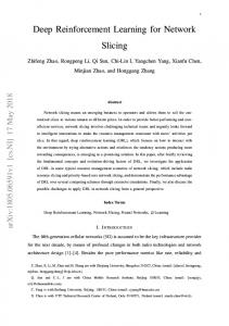
Longitudinal reinforcement strain (µ strain)
at flexure crack at diagonal crack 75% of ultimate load at ultimate load predicted strain
0
Longitudinal reinforcement strain (µ strain)
G8-8 37 328 0.028 550 0.046 2688.6 0.223 G8-8H 44.6 457 0.031 746 0.051 2532.8 0.174 G8-8V 44.6 457 0.031 680 0.047 3236.4 0.223 G8-8VH 37 372 0.031 681 0.057 2904.2 0.241 !! : initial flexure crack load; !! : diagonal ag shear crack load, !! : ultimate load at failure
Fig. 6 - Strain distribution of FRP longitudinal reinforcement
3.5. Measured strains in longitudinal (tie) reinforcement The strain distribution along the longitudinal reinforcement at various stages of the loading is presented in Fig. 6. First, at the formation of the flexure crack, the strain distribution for the tested deep beams was very low and following a manner similar to bending moment. Afterword, once the diagonal crack formed; the strain distribution in the longitudinal bar significantly increased in the cracking side of the beam, which was obvious for all specimens. After the formation of the first diagonal crack, the strain distribution tended to become closer with uniform increase in the strain. The nearly uniform strain distribution in the longitudinal reinforcement indicated the development of the arching action mechanism in the tested deep beams. Gaps between data points at span of 3000 mm in G8-8H and 750 mm in G8-8V were due to offscale strain gauge readings. The strain of the longitudinal reinforcement in all specimens did not reach
Page 5 of 6
51% of ultimate tensile strain of FRP bars. No signs of anchorage problem were observed in any of the tested specimens. All FRP strain gauges in Beam G8-8 were off-scale at the ultimate load. However, in a previous study for Farghaly and Benmokrane (2013), the predicted strain at ultimate load for deep beams without web reinforcement was approximately similar to the measured strain. The same results observed in case of G8-8V. However, in the current study, the predicted strains in case of deep beams with horizontal web reinforcement (G8-8H and G8-8V) were higher than the measured strains as shown in Fig. 6. Thus, the presence of horizontal web reinforcement reduced the strains in the longitudinal bars.
4. Conclusions A total of 4 full-scale concrete deep beams measuring 5000 x 1200 x 300 mm were constructed and tested under two-point loading to failure. The studied variables were the effect of the presence of web reinforcement. The experimental results were investigated considering the cracking and ultimate load, deflection response, and strains. On the basis of the experimental results the following conclusions were drawn: 1. All beam specimens exhibited a nearly bilinear response until failure. The specimens had similar stiffness up to the initial flexural crack, followed by a reduction in stiffness with different tendency. 2. The presence of web reinforcement distributed the stresses along the length of the diagonal strut resulting in a failure mode identified as crushing of the diagonal concrete strut. Meanwhile, in case of no web-reinforced specimen, the stresses were localized close to the loading point resulting in concrete crushing in this area along with the failure of the diagonal concrete strut. 3. The web reinforcement had no significant effect on the cracking load or the ultimate load capacities.The web reinforcement, however, showed a clear effect in controlling the crack width especially for the vertical reinforcement. 4. Accordingly, the purpose of using FRP web reinforcement specified in CSA S806 (2012) to control crack width is more appropriate than that specified in ACI 318 (2011) to increase the ultimate load capacity. 5. The formation of the tie action was confirmed by the nearly uniform strain distribution in the longitudinal reinforcement. Although the number of specimens tested in this study (4 deep beams) is not enough to suggest the shear behavior of various types of deep beams, it clearly shows, however, the necessity to address the web reinforcement effect in CSA S806 (2012) and adopting a strut-and-tie model in ACI 440.1R (2006). Further study is going to be carried out to investigate such issues.
5. References ACI Committee 440 (2004). “Guide Test Methods for Fiber-Reinforced Polymers (FRPs) for Reinforcing or Strengthening Concrete Structures (ACI 440.3R-04).” ACI, Farmington Hills, MI, 40 pp. ACI Committee 440 2006. “Guide for the design and construction of concrete reinforced with FRP Bars (ACI 440.1R-06).” ACI, Farmington Hills, MI, 44 pp. ACI Committee 318 (2011). “Building Code Requirements for Structural Concrete and Commentary (ACI 318-11).” ACI, Farmington Hills, MI, 473 pp. ANDERMATT, Matthias, ADAM, Lubell, “Strength Modeling of Concrete Deep Beams Reinforced with Internal Fiber-Reinforced Polymer,” ACI Structural J., Vol. 110, No. 4, July 2013, pp. 585-495. BIRRCHER, David, TUSCHETER, Robin, HUIZINGA, Matt, BAYRAK, Oguzhan, “Minimum Web Reinforcement in Deep Beams,” ACI Structural J., Vol. 110, No. 2, March 2013, pp. 297-306. CSA S806 (2012). Design and construction of building components with fiber-reinforced polymers. Canadian Standards Association, Mississauga, Ontario, Canada, 208 pp. FARGHALY, Ahmed, BENMOKRANE, Brahim, “Shear Behavior of FRP-Reinforced Concrete Deep Beams without Web Reinforcement,” J. Compo. Const., Vol. 17, No. 6, December 2013.
Page 6 of 6