KDDI R&D Laboratories Inc. ABSTRACT. Presenting images from a free viewpoint is a promising in- teractive video application. Though reference images from.
EFFECTIVE INTERPOLATION FOR FREE VIEWPOINT IMAGES USING MULTI-LAYERED DYNAMIC BACKGROUND BUFFERS Atsushi Matsumura, Sei Naito, Ryoichi Kawada, Atsushi Koike, and Shuichi Matsumoto KDDI R&D Laboratories Inc. ABSTRACT Presenting images from a free viewpoint is a promising interactive video application. Though reference images from one viewpoint and their depth maps are often used to render free viewpoint images, picture quality degradation may occur because of lack of information in background regions that are occluded by foreground regions. In this paper, an interpolation method for free viewpoint images using multi-layered dynamic background buffers is proposed. In the proposed method, the buffers, updated using the reference images divided in each frame, are used to store the background regions, and the output images are interpolated by the background buffers. Since the background buffers are created and updated using only the reference images and their depth maps, additional information on the background buffers is not required for the interpolation. The effectiveness of the proposed method was evaluated by several simulation experiments. 1. INTRODUCTION
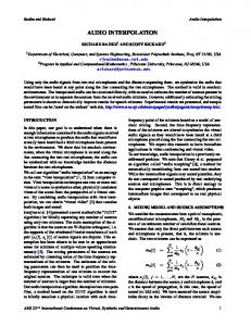
defines multi-layered background buffers, which are created and updated dynamically in each frame, and the free viewpoint image is interpolated using these buffers. Since these buffers are created and updated by the reference images and their depth maps, the method conducts the interpolation without additional information for buffers. 2. CONVENTIONAL METHODS FOR FREE VIEWPOINT IMAGES A general rendering method for free viewpoint images is shown in the Generation frame in Fig. 1. To estimate each pixel of the free viewpoint image, corresponding pixels are searched from a reference image using its depth map, and then the corresponding pixels are copied into the free viewpoint image. However, lack of information on occluded background regions may cause picture quality degradation. To solve the problem, an interpolation method using background sprite was proposed [4]. The flow is shown in Interpolation frame in Fig. 1. However, since a complete background image has to be
Presenting images from a free viewpoint is very attractive as one of the interactive applications of next generation. To realize the system, video materials including 3-D information, such as 3-D position information of the objects [1] or images captured by surrounding video cameras [2], are usually used. However, they have difficulties as the former ones require special video cameras for obtaining accurate 3D position information, and video cameras have to be fixed for capturing the latter ones. Meanwhile, images from one viewpoint, called reference images, and their depth information of each pixel, called depth maps, are also popular as 3-D video materials [3]. Though output images have limited viewpoints, these materials are applicable in various environments since cameras do not have to be fixed, and they can be applied to the representative transmission systems, such as MPEG-4, by treating the depth maps as auxiliary information of the reference image. However, these materials usually cause picture quality degradation in output images because of the lack of information on background regions occluded by foreground regions. As a solution to the problem, a method using background sprite is proposed [4]. However, there are several limitations in applying the method, such as the need to obtain the sprite beforehand. Considering the above circumstances, a novel interpolation method is proposed in this paper. The proposed method
0-7803-8554-3/04/$20.00 ©2004 IEEE.
Generation Reference Image Depth map
Rendering Free Viewpoint Image Free Viewpoint Image Interpolation
Background Sprite
Interpolating Free Viewpoint Image
Interpolated Free Viewpoint Image
Fig. 1. The flow of the conventional methods.
1377
obtained in advance, the interpolation method has some difficulties, such as a high bit-rate transmission or more storage data size are required or environments for capturing are limited. 3. THE PROPOSED METHOD Fig. 2 shows the flow of the proposed method for interpolation that overcomes the difficulties discussed in Section 2. An image rendered from a reference image and its depth map is created as a tentative free viewpoint image in each frame. Meanwhile, as a preprocess for updating multilayered background buffers, the reference image is divided according to its depth map [5]. Then the divided images are integrated into the corresponding background buffers. Finally, the tentative free viewpoint image is interpolated by the background buffers. The detail is described below. 3.1. Rendering tentative free viewpoint image To render free viewpoint images, a definition of the viewpoint is required. In our method, the viewpoint is defined by 3 × 3 matrix R � , indicating an angle of the viewpoint, and 1 × 3 vector t � , indicating a position of the viewpoint. By using R� and t� , the coordinates of corresponding pixels between the pixel in the reference image I, located at (u, v), and the pixel in the free viewpoint image A, located at (u�� , v �� ), are indicated as equation (1), � � (u�� , v �� , 1) × DI (u, v)R� (u, v, 1)T + t� = 0, where DI (x, y) indicates the depth of I(x, y). Then
Reference Image
Rendering Tentative Free Viewpoint Image
Depth map
Dividing Reference Image
the free viewpoint image is rendered by equation (2), A(u�� , v �� ) = I(u, v),
where A(u�� , v �� ) indicates the pixel located at (u �� , v �� ) in image A, and I(u, v) indicates the pixels located at (u, v) in image I. Every following pixel is indicated as the same description. 3.2. Dividing the reference image As a preprocess of creating and updating the background buffers, the reference image is divided using the following processes. Firstly, the histogram of D I is analyzed using equation (3), � � (2n + 1) S n×S V , (3) = ν(n+1)×S 2 where νji indicates the number of pixels whose depth is between i and j, S indicates step size for analyzing, and n is an integer. Secondly, V � (n) is calculated from V (n) using a Gaussian filter aimed at smoothing. Thirdly, the value of V � (n) is evaluated in numerical order of n. As a result, n which gives ith local minimum of V � (n) is extracted as ni , and mini indicates S × ni in the following. Finally, image I is divided as Im (m = 0, 1, · · · , M ) using equation (4), I� m (x, y) = I(x, y) null
Tentative Free Viewpoint Image
Background Buffers
Interpolating Free Viewpoint Image
Interpolated Free Viewpoint Image
Fig. 2. The flow of the proposed method.
if minm ≤ DI (x, y) < minm+1 otherwise ,
(4)
where, min0 is −∞ and minM+1 is ∞. (1)
3.3. Rendering and updating background buffers In the proposed method, each divided image is integrated into the corresponding background buffer following the processes described below. For the top frame, background buffer U m (m = 1, 2, · · · , M ) is rendered by copying the corresponding image I m , where U0 is not rendered since I 0 is regarded as foreground. Otherwise, Um is updated as follows. Firstly, more than 8 corresponding points between I m and Um are searched. Secondly, a projection matrix that satisfies equation (5) is calculated using these points,
Divided Reference Images Updating Background Buffers
(2)
� , 1)T = 0, (uIm , vIm , 1)T × Bm (u�Um , vU m
(5)
� where, (uIm , vIm ) and (u�Um , vU ) are the coordinates of m the corresponded pixels between I m and Um . Finally, Um is � updated by substituting (u Im , vIm ) and (u�Um , vU ), which m are calculated by equation (5), for equation (6), � )← Um�(u�Um , vU m � ) Um (u�Um , vU m Im (uIm , vIm )
if Im (uIm , vIm ) =null , otherwise
(6)
where the left arrow indicates substituting a right value for a left value. Since B m is sensitive for matching error, calculating Bm from numbers of matching points is desirable. In the simulation experiment, B m is computed from 400 points by using renormalization method[6].
1378
3.4. Interpolation for free viewpoint image Non-rendered pixels in the tentative free viewpoint image are interpolated using the background buffers obtained in Section 3.3. The detail is as follows. Firstly, more than 8 corresponding pixels in the tentative free viewpoint image and each buffer, U 1 , U2 , · · · , UM , are searched. Secondly, projection matrices B � 1 , B� 2 , · · · , B� M are calculated by substituting these corresponding pixels for equation (7), � (u�Um , vU , 1)T × B� m (u�� , v �� , 1)T = 0, m
(7)
� ) are the coordinates of the where, (u�� , v �� ) and (u�Um , vU m corresponding pixels in A and U m . Thirdly, the free viewpoint image is interpolated by applying equation (8), �� �� A(u � ,v ) ← � ) Um (u�Um , vU m �� �� A(u , v )
if A(u�� , v �� ) =null . otherwise
(8)
Finally, A is output to users. 4. REDUCING CALCULATION COSTS IN SERVER-CLIENT SYSTEMS Reducing calculation costs of client is required for realtime video output in the server-client system since searching the corresponding pixels between the reference image and background buffers incurs great expense. Server
Reference Image
Depth map
Dividing Reference Image Divided Reference Images Renewing Background Buffers
Projection Matrices
Client Dividing Reference Image Rendering Tentative Free Divided Viewpoint Image Reference Images Updating Background Buffers Tentative Free Viewpoint Image
Fig. 3 shows the flow that satisfies such a requirement. In the method, the same buffers as those the clients have are created in the server, and the processes in 3.2 and 3.3 are executed to calculate B 1 , B2 , · · · , BM . Since these matrices are obtained without depending on the viewpoint, the results are applicable to the clients without modifications. Elements of these matrices are stored or transmitted in each frame. In the clients, B 1 , B2 , · · · , BM are reconstructed with these elements and they are used for the processes in Section 3.3. Since each matrix is constructed from 9 real numbers, the size of the data is much smaller than those of the reference images and depth maps. Therefore, the method is applicable under the band-limited transmission or memory limited storage system. These matrices can be regarded as auxiliary data as well as depth maps.
Background Buffers
Interpolating Free Viewpoint Image
5. EXPERIMENTAL RESULTS To evaluate the effectiveness of our proposed method, some experiments were evaluated. The experiments used luminance signals of the Tulip Garden and Red Leaves, which are the materials in HDTV stereoscopic standard sequences created by the Institute of Image Information and Television Engineers Japan and cut by 960×480. The left images were used as reference images, and their depth maps were estimated from corresponding pixels of the right images, whose distances between the left images are 6.5cm. By creating free viewpoint images from the reference images and the depth maps, the effectiveness was evaluated. The size of each background buffer was defined as double in the horizontal axis and vertical axis. Each background image in the top frame was rendered into the center of the corresponding background buffer with the same size. Firstly, percentages of non-rendered pixels are shown in Fig. 4, where non-interpolated results are also demonstrated for comparison. These results indicate that interpolated pixels increase as the frame number increases in our method. Both results show that the percentages of non-rendered pixels in the thirtieth frames are reduced less than 1/7 compared to the results of non-interpolated method. Secondly, average PSNRs between the interpolated pixels and the corresponded pixels of original right image are shown in Fig. 5, where the results using the nearest pixels for interpolation are also displayed as a comparison. Both results show the gain of PSNR, especially they indicate increasing a maximal 3.5dB in Tulip Garden. Finally, the thirtieth frame created using our proposed method and non-interpolated method is shown in Fig. 6, where non-rendered pixels are drawn in white. Higher quality images are obtained using the proposed method by accurate interpolation. 6. CONCLUSION
Interpolated Free Viewpoint Image
Fig. 3. The flow of the proposed method applied the serverclient systems.
This paper proposed a novel interpolation method to obtain high quality free viewpoint images using multi-layered background buffers. Since the background buffers are created by reference images and depth maps dynamically, the
1379
Ratio between Non-rendered Pixels and All Pixels(%) 1.0
PSNR(dB)
Proposed Method Non-Interpolated Method
21
0.9
20.5
0.8
20
0.7
19.5
0.6
19
0.5
18.5
0.4
18
0.3
17.5
0.2
17
0.1
16.5
0
Interpolated by Proposed Method Interpolated by Nearest Pixel
22
21.5
0
5
10
15
20
25
2.2
5
Frames
10
15
20
PSNR(dB)
30
Frames
Interpolated by Proposed Method Interpolated by Nearest Pixel
18
Proposed Method Non-interpolated Method
17.5 17 16.5
2.0 1.8
16
1.6
15.5
1.4 1.2
15
1.0
14.5
0.8
14
0.6
13.5
0.4
0
5
10
15
20
0.2 0
25
(a): Tulip Garden
(a): Tulip Garden Ratio between Non-rendered Pixels and All Pixels(%)
0
30
0
5
10
15
20
25
25
30
Frames
(b): Red Leaves
30
Frames
(b): Red Leaves Fig. 5. PSNRs of interpolated pixels. Fig. 4. Percentages of non-rendered pixels. method can interpolate output images without modifying conventional 3-D video materials. In addition, we proposed a method to reduce calculation costs when applying the method to the server-client system. The experimental results demonstrated the effectiveness of our method by comparing the ratio of non-rendered pixels, PSNRs, and output images among conventional methods. 7. REFERENCES
(a): Non-interpolated Method (Tulip Garden)
(b): Proposed Method (Tulip Garden)
(c): Non-interpolated Method (Red Leaves)
(d): Proposed Method (Red Leaves)
[1] Saied Moezzi, Li-Cheng Tai, and Philippe Gerard, “Virtual View Generation for 3D Digital Video,” IEEE Multimedia, Vol. 4, pp. 18–26, May 1997. [2] Takeo Kanade and Peter Rander, “Virtualized Reality: Constructing Virtual Worlds from Real Scenes,” IEEE Multimedia, Vol. 4, pp. 34–47, May 1997. [3] Christoph Fehn, “About the Impact of Disparity Coding on Novel View Synthesis,” MPEG02/M8676, Jul. 2002. [4] M. Lee, W Chen, C.B. Lin, Gu. T. Markoe, S. I. Zabinsky, and R. Szeliski, “A layered video object coding system using sprite and affine motion model,” IEEE Transactions. Circuits & Systems for Video Technology, Vol. 7, No. 1, pp.130–145, Feb. 1997. [5] R. Szeliski and P. Golland, “Stereo Matching with Transparency and Matting,” in Sixth International Conference on Computer Vision, Bombay, India, pp. 517524, 1998.
Fig. 6. The thirtieth frame of non-interpolated and interpolated images. [6] C. Matsunaga and K. Kanatani, “Calibration of a moving camera using a planer pattern: Optimal computation, reliability evaluation and stabilization by model selection”, Proceedings of the 6th European Conference on Computer Vision, P.26, Jul. 2000,
1380