Effective User Interface Design for Rescue Robotics M. Waleed Kadous
Raymond Ka-Man Sheh
Claude Sammut
Centre for Autonomous Systems School of Computer Science and Engineering University of New South Wales Sydney NSW 2052
School of Computer Science and Engineering University of New South Wales Sydney NSW 2052
Centre for Autonomous Systems School of Computer Science and Engineering University of New South Wales Sydney NSW 2052
[email protected]
[email protected]
[email protected] ABSTRACT
Keywords
Until robots are able to autonomously navigate, carry out a mission and report back to base, effective human-robot interfaces will be an integral part of any practical mobile robot system. This is especially the case for robot-assisted Urban Search and Rescue (USAR). Unfamiliar and unstructured environments, unreliable communications and many sensors combine to make the job of a human operator, and hence the interface designer challenging. This paper presents the design, implementation and deployment of a human-robot interface for the teleoperated USAR research robot, CASTER. Proven HCI-based user interface design principles were adopted in order to produce an interface that was intuitive and minimised learning time while maximising effectiveness. The human-robot interface was deployed by Team CASualty in the 2005 RoboCup Rescue Robot League competition. This competition allows a wide variety of approaches to USAR research to be evaluated in a realistic environment. Despite the operator having less than one month of experience, Team CASualty came 3rd, beating teams that had far longer to train their operators. In particular, the ease with which the robot could be driven and high quality information gathered played a crucial part in Team CASualty’s success. Further empirical evaluations of the system on a group of twelve users as well as members of the public further reinforce our belief that this interface is quick to learn, easy to use and effective.
Rescue robot design, user interface design, human robot interface
Categories and Subject Descriptors
Victim identification Detect and describe victims and their characteristics, such as shape of the body, heat, motion etc.
H.4 [Information Systems Applications]: Miscellaneous
1. INTRODUCTION Teleoperation remains an important part of our interaction with robots. Varying degrees of autonomy are starting to become possible however until full autonomy is present, some form of direct operating interface will be required and even when it becomes possible, alternative forms of user interfaces will be needed for human-robot co-operation. The design of user interfaces for robot awareness and control are critical to the success of applications in mobile robotics. One particularly challenging domain for telerobotics is urban search and rescue (USAR). In the future, the first responders on the scene of an earthquake or other disaster will deploy an autonomous fleet of robots. These robots co-ordinate amongst themselves, search the area, identify survivors, deliver assistance, monitor their conditions and assist human rescuers when they arrive. Whilst such dreams are a long way off, technologies are already being developed that work towards this goal. In the meantime, USAR robots must have at least partial teleoperation. A robot designed for USAR must address three distinct subproblems: Mobility and situational awareness Safely traverse stairs, ramps and rubble without bumping victims, triggering secondary collapses or damaging the robot.
Design, Human Factors
Mapping Generate useful maps that show the location of victims and any nearby landmarks and present them intuitively.
Permission to make digital or hard copies of all or part of this work for personal or classroom use is granted without fee provided that copies are not made or distributed for profit or commercial advantage and that copies bear this notice and the full citation on the first page. To copy otherwise, to republish, to post on servers or to redistribute to lists, requires prior specific permission and/or a fee. HRI’06, March 2–4, 2006, Salt Lake City, Utah, USA. Copyright 2006 ACM 1-59593-294-1/06/0003 ...$5.00.
In order to evaluate the success of our approach to USAR, we have entered the Robocup Rescue competition. The RoboCup Rescue Robot League (RRL) aims to provides a standardised and relatively objective measure of performance for research related to USAR. Doing so means that very early in the development cycle, new technologies can be practically evaluated RRL Standard Arenas are intended to be different, but comparable, real-world environments where robots may be
General Terms
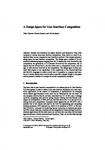
Figure 1: Examples of RoboCup RRL Standard Arenas. Left is the USAR test facility at the University of Technology, Sydney and right is the competition arena at Osaka tested, much like how various golf courses are different but comparable environments [3]. Examples of RRL Standard Arenas are shown in Figure 1. Whilst each is different, they are designed based on the same rules thus results of testing in the different arenas may be compared. They also intend to be practical approximations to “real world” disaster sites thus debris, loose material, low clearances, victims with varying states of consciousness, multiple levels, variable lighting and radio blackspots are replicated. For practical reasons, other factors such as water and mud are not included and unstable collapses, dust and fire are simulated by lightweight debris, curtains and “fake” heat sources. In this paper, we first discuss the hardware platform used in this research. We then present prior work in the field, and explain some general design principles. We then show how we have taken these principles and implemented them in our user interface. Evaluation was performed at the competition, on members of the general public and during more formal testing in our lab. Finally, we draw conclusions and show how this work could be extended in future.
2.
HARDWARE PLATFORM
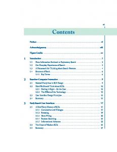
Figure 2 shows annotated views of the robot, dubbed CASTER (Centre for Autonomous Systems Tracked Exploratory Robot), including sensors. The following subsections describe the sensing fitout in greater detail, individually and from the perspectives of mobility and situational awareness, victim identification and mapping.
2.1 Locomotion CASTER is built on a Yujin Robotics Robhaz DT3 base [6]. This robot base is weatherproof and extremely robust, indeed it is designed to survive the detonation of small explosives. The robot has two pairs of rubber tracks for locomotion. The front pair of tracks follow a triangular path, allowing the DT3 to climb over obstacles and stairs whilst a conventional flat rear pair provide additional traction. Turning is accomplished by differentially driving the right and left tracks.
2.2 Sensors CASTER carries a number of sensors relevant to HRI. These include a TracLabs Biclops pan-tilt unit on which are mounted a Logitech webcam, CSEM SwissRanger SR-2 time-of-flight range imager, FLIR ThermoVision A10 thermal camera and a Sony ECM-MS907 stereo microphone. There are also 3 auxiliary cameras for situational awareness and an ADXL311 accelerometer to determine pitch and roll.
Figure 2: Top-down and oblique view of CASTER
2.3 Mobility and Situational awareness The DT3 robot base can move in highly unpredictable ways on unstructured terrain due to its length, articulation and skid-steering properties. Given the difficulty of the environment itself and the very real prospect of becoming stuck or unstable, situational awareness is critically important. Four colour cameras provide visual feedback to the operator. A high resolution webcam on the pan-tilt unit forms the main driving camera and is able to observe the area immediately in front of the robot as well as to the sides and rear. Large sensing shadows near the robot’s left and right shoulders are covered by two auxiliary cameras mounted at the rear, which also assist in lining up the robot with openings and obstacles. A wide angle rear-view camera covers the sides and rear of the robot and assists in avoiding collisions with obstacles that may not be visible from the main camera. It is mounted on a vibration damped flexible boom to prevent damage. CASTER also carries high powered lighting, positioned so as to not shine directly into any of the cameras. Combined with the main camera’s ability to cope with highly varied lighting conditions, CASTER is able to operate in lighting conditions ranging from floodlit to complete darkness. The microphone provides the operator with feedback on the robot’s behaviour. By listening, it is possible to determine if tracks are slipping, if motors are being loaded, if the robot is high-centered or if it is brushing up against an obstacle. Finally, an accelerometer provides information on the robot’s attitude and allows the operator to make decisions as to CASTER’s stability.
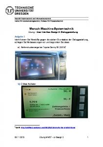
Figure 3: PackBot EOD user interface - Photo c/o Adam Jacoff
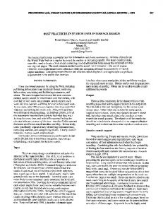
Figure 4: Toin Pelican user interface
2.4 Victim identification and diagnosis Three groups of sensors were used for victim identification – the four colour cameras, the thermal camera and the stereo microphone. In addition, the range imager was used to accurately determine the position of victims once identified (see Section 2.5). To aid victim identification, the thermal image data was superimposed on the main camera image. These two groups of sensors together provide 3 signs of life – heat, form and motion. The stereo microphone was intended for use in locating victims, identifying their state and providing an additional sign of life. Unfortunately technical issues resulted in the output being mono-only, albeit with a high degree of directionality. However it was still useful for identifying additional signs of life.
Figure 5: IUT Microbot user interface
2.5 Mapping The core of CASTER’s mapping capabilities lies in the range imager [5], which provides 3 channels of information per pixel – distance, reflected near-infrared intensity and ambient near-infrared intensity. Mounted on the pan-tilt unit along with the colour main camera and thermal imager, 7 channels of information (distance, near IR reflectance, near IR ambient, red, green, blue and temperature) are available for each pixel and allow for the construction of very informative 3D maps, as well as provide a potentially very rich data set for further image processing. The pan-tilt unit assists in this process by providing very accurate positioning of the sensors, thus allowing the accurate integration of sensor measurements taken from different directions. An accelerometer measures the robot’s pitch and roll, allowing 3D data to be pre-rotated to the horizontal.
3.
PREVIOUS WORK ON RESCUE ROBOT INTERFACES
Current human-robot interfaces for mobile robots are often hard to use, confusing and suffer from both information overload (too much inappropriate information) and poor situational awareness (a lack of appropriate information about the robot’s environment [2]). Mostly developed by the same people who developed the robot itself, such interfaces also tend to be highly unintuitive and non-standard [8]. Further, it can not be assumed that commercial systems are necessarily better designed. The iRobot PackBot EOD control unit shown in Figure 3, for example, is driven by two 6 degrees of freedom pucks. Depending on the task at hand,
in some cases the left puck drives the robot whilst the right puck controls the camera and in other cases the reverse is true. Sometimes a twist of the puck to the left rotates the flippers forward, in others a roll of the puck to the right rotates the flippers forward. Learning and memorisation of this interface appears to have been a problem; an extensive “cheat sheet” had to be glued onto the control unit. Robots with more complex capabilities suffer from this problem to an even greater degree. RoboCup Rescue Robot League entries must generate maps and record information on victims and landmarks. The problem of information overload is very real yet surprisingly little seems to have been done in addressing this problem. Examples of interfaces appearing in this competition include those from IUT Microbot (2003 3rd place, Figure 5) [7] and Toin Pelican (2004 1st place, Figure 4) [4]. The ability to both drive the robot, often using several cameras, and record data about the robot’s surroundings whilst maximising the operator’s throughput is clearly not assisted by the design of these interfaces, with multiple overlapping windows and often multiple screens that need to be consulted at the same time. Some groups have made advances in this area. The video display plays an integral part in operator feedback and effective control of the video feed, and the effective presentation of information over and around the video feed, makes a big difference to the success of a the human-robot interface [1, 8]. Two examples of interfaces that attempt to maximise the effectiveness of this display by intuitively combining it with other relevant information include the RoBrno (2003
Figure 6: RoBrno user interface
examples of specific attributes that define a good humanrobot interface do not yet exist. However, several guidelines can be proposed that can help shape the design of a good interface. Principles from human-computer interaction research provide a starting point and emphasise the importance of interfaces that are visually and conceptually clear and comprehensible, aesthetically pleasing and compatible with the task at hand and the user [8]. In [8], a number of design principles for HCI and HRI are highlighted. Based on these principles, we have selected what we believe to be the four most important ones. Awareness The operator should be presented with enough information to build a sufficiently complete mental model of the robot’s external state (the robot’s surroundings and orientation) and internal state (system status). Note that this should be tempered with the requirement for familiarity – information overload is a very real risk. Efficiency There must be as little movement as possible required in the hands, eyes and, equally importantly, focus of attention.
Figure 7: U Mass Lowell user interface
1st place, Figure 6 [11] and an interface developed at the University of Massachusetts Lowell (Figure 7) [1]. In both cases, the focus is on providing information without requiring the operator to divert attention from the main video screen. The RoBrno interface does this by providing transparent overlays over the video screen. They also go one step further by providing the operator with a tracked head-mounted display so they may move the robot’s camera simply by moving their head. Wherever possible, information is displayed graphically. For instance, the camera’s direction is displayed as a crosshair and not a number. The current camera being viewed is not indicated by text, instead a graphic of the robot is shown with the current camera and drive state indicated by colours. Where numbers are used, they are used sparingly and highlighted by suitable colours when their value becomes important. The U Mass. Lowell interface in contrast is somewhat more conventional, comprising of a video screen but seeks to either overlay relevant information, such as thermal imagery, over the video feed or adds relevant information to the borders of the video feed, such as the rearview camera, sonar and mapping. This interface also provides varying degrees of autonomy and an alerting system that provides specific prompts to the operator regarding critical status indicators and suggestions for appropriate actions. By having the system monitor the robot’s status and only disturb the operator’s attention when necessary, information overload due to the need to monitor multiple gauges and numbers is avoided.
3.1 Design Principles The field of human-robot interfaces is still in its infancy;
Familiarity Wherever possible, concepts that are already familiar to the operator should be adopted and unfamiliar concepts (including those that induce information overload) minimised or avoided. If necessary, information should be fused to allow for a more intuitive presentation to the operator. Responsiveness The operator should always have feedback as to the success or failure of actions.
4. USER INTERFACE DESIGN For safe, effective and rapid control of the robot, the robot must operate as an embodiment and extension of the operator. In other words, the operator must cognitively place themselves in the same position as the robot. Two barriers exist in achieving this goal. The first barrier comes from the robot often having a very different morphology to the human operator. A suitable mapping between what a human considers as intuitive movement must somehow translate to sensible movements in the robot. Whilst a motor vehicle moves very differently to a human, most operators are already familiar with how to control a motor vehicle so instead of mapping human-like movement to robot movement, a mapping from motor-vehicle-like movement may be sufficient. The second barrier is that of sensing and perception. The operator is not in the same place as the robot and the sensors on the robot may not match those that a human is used to. In order to overcome this barrier, familiar sensors must be presented in a way that provides the operator with good situational awareness and allows them to form a good mental model of the environment. Foreign sensors such as thermal cameras or range sensors must be presented using appropriate metaphors. There is one industry that already tackles these issues head-on, with considerable success. The computer games industry, in particular first-person-shooter computer games, share many of the same user interface problems that mobile robots do. The characters being controlled may be morphologically different from the operator and, indeed their
morphology may change. For instance, the one character may switch between walking to flying a plane to driving a car to piloting watercraft, often in quick succession. Additional sensors such as simulated thermal vision, “enemy trackers” and the like may be available to the operator. Additionally, time and accuracy are critical. The interfaces developed must be intuitive, standard across different games and use conventional hardware. For instance, the primary method of feedback is the video screen. The current sixth generation of first-person shooters, such as Half-Life 2 and Unreal Tournament 2004 have highly polished user interfaces that largely address these issues very effectively. We have used experiences from these games, as well as the guidelines outlined in Section 3.1, to guide the design of our interface, which is shown in Figure 8. The layout of the display resembles the heads-up display in many computer games. The main video display appears full screen. Additional views and graphics appear around the periphery of the screen with the exception of the aiming graphic. In spirit, the work is most similar to the RoBrno user interface, but our interface offers a number of advantages, including: overlays of different sensors such as thermal cameras, integration of victim and landmark placement in 3D, used of 3D direction indicators for a more consistent user experience, the use of hotkeys for camera placement, the display of accelerometer data, the addition of the auxiliary cameras, and doing away with numbers and text on the display altogether. We believe that despite the additional sensors CASTER has over Orpheus (RoBrno’s robot), our user interface is similar if not better in usability than the RoBrno design. However, an objective comparison is not possible, as RoBrno did not compete. In keeping with the driving experience, the rearview display appears at the top of the screen. In a break from tradition, it is not inverted as the robot skid steers; direction of turn does not invert if the robot is driven backwards. The forward facing side views are placed low and to the sides of the main display. Thus, all the cameras are visible at the same time. Their positioning is intuitive and match their positions on the robot itself. If the operator wishes to study the main view without clutter, all the extra views may be hidden with a single keypress. Computer generated graphics, such as the “artificial horizon”, network strength indicator and speed bar alleviate the need for text in the interface. Indeed, no text appears in the driving display at all. So that they do not block the main camera, they are rendered transparently with the exception of a thin solid border to maintain demarcation. Based on the equivalent displays found in flight simulators, mobile phones and bar graphs, these graphics are immediately recognisable and do not require much thought to interpret. A transparent computer generated 3D arrow appears in the middle of the screen and always points towards the front of the robot. This data is obtained directly from the pantilt unit’s sensors. The arrow allows the direction of view to be determined at a glance and assists in driving whilst not looking forward, if such an action is desired. This helps especially in terrain that is difficult to traverse and where robot actions may not yield the expected movement in the environment. Out of several alternative arrangement, such as arrows pointing in alternative directions, bar graphs or crosshairs, this arrangement was found to be the most intuitive after rudimentary tests were done with the operator.
Images from the thermal camera may be overlaid onto the main camera image. To reduce clutter, areas of the image below a threshold temperature are unaffected whilst those above are tinted with a colour between red and yellow depending on temperature. Experimentally, it was found that tinting areas between 30◦ and 35◦ was effective. This maximises awareness by integrating different sensors into a single display, while simultaneously improving efficiency. The user may also optionally observe the raw thermal image, which appears above the right side camera view by pressing a key. Intuitive control is also obtained by adopting controls similar to those used in first-person-shooter computer games such as Quake, Half-Life and Unreal. The left hand operates the keyboard and controls robot movement via the keys W, A, S and D, which are arranged in an inverted-T. For instance, the W key moves the robot forward as long as it is held down. The right hand operates a mouse and controls the pan-tilt unit by holding down the left mouse button and dragging. The mouse is not captured to allow the operator to, optionally, run the driving interface in a window in conjunction with other programs such as a notepad or messaging system. The scrollwheel on the mouse controls the robot’s forward, reverse and turning speeds and operates as a throttle preset. Due to control lag, moving the pan-tilt unit long distances with the mouse became excessively time consuming, thus preset positions were added. These are activated through hotkeys, rapidly moving the pan-tilt unit to pre-defined positions such as all-the-way-back or just-in-front-of-left-track. The operator could then refine the position with the mouse. The number keys on top of the keyboard were chosen for the hotkeys. Other keyboard controls are available for initiating a scan macro action, hiding additional telemetry information and indicating the presence of victims and landmarks. For ease of memory, the keys were chosen based either on their spatial layout on the keyboard (for instance, “1” moves the pantilt unit to the far left, “9” moves it to the far right) or because they represent the first letter of the concept (for instance, the thermal view is obtained by pressing “T”). The key assignment may be adjusted to the operator’s taste. No additional interface or context switch is used to indicate the position of a landmark or victim. Instead, from within the driving interface the operator positions the mouse cursor over the victim or landmark and, instead of dragging with the left mouse button, clicks the middle mouse button. Based on the cursor’s image position, the range imager locates the corresponding point in 3D space and automatically annotates the map. The cursor appears as a blue square to indicate the area over which the range imager’s measurement will be averaged. The interface then prompts the user for details of the landmark or victim via a text entry window. This window is small and does not obstruct the main driving interface so as to reduce the disorientating effects of the context switch. Typing text into this entry window is the only occasion that requires the operator to deviate from the left-hand-on-keyboard, right-hand-on-mouse configuration; the use of voice recognition is a possible extension for this purpose. It is also important to note that this layout specifically avoids the driver having to use two interfaces – one for driving and one for victim and landmark placement. Many al-
Figure 8: Screen shot of the user interface ternative interfaces require the operator to divert attention from the driving view for prolonged periods in order to determine where a victim or landmark is to be located on a separate map. The use of a 3D range imager gives us greater flexibility in this regard and our interface takes full advantage of it. The development process was iterative. Whenever a new feature was added it was incrementally evaluated with the operator that was to drive the vehicle in the competition. The user interface for driving was stabilised approximately one month before the competition. Prior to the competition, there was only four days of “dry run” practice at the University of Technology Sydney USAR test facility. Outside of these times, the testing had to be done in a normal “open plan” office area without the typical obstacles.
5.
EVALUATION
Once the user interface was developed and stabilised, it was tested in three main ways: in the competition, feedback from members of the public and a more rigorous process to empirically measure user interface issues.
5.1 Competition performance In the competition, Team CASualty came second in the preliminary round, second in the semi-finals and third in the final round. It is our belief that the user interface was a significant component of our eventual success; especially considering that our driver had only had a few days of driving experience in a rescue arena. A significant disadvantage we encountered was higher than anticipated video delays (“lag”), of up to several seconds. This caused inaccuracies,
resulted in the need to operate the robot much more slowly than we had planned and resulted in one major accident where the robot became inverted. Were it not for these issues, perhaps the team would have performed better. Our evaluation of the user interface was assisted by “overthe-shoulder” and in-arena video recordings provided by the National Institute of Standards and Technology (NIST) of three of the competition missions. The evaluation we present below is based on preliminary analysis of these recordings and focus on “critical incidents”, such as victim identifications or complex manoeuvres. To give an example of the effectiveness of the user interface, in semi-final 3, the robot was driven to an open area of the arena known as the stepfield and in which three victims were immediately observed. This happened approximately 3 minutes into the run. The operator took approximately 65 seconds to complete a scan of the environment, generate a 3D map of the complete stepfield area and tag 3 victims and one landmark. The robot was then driven over the stepfield and stopped next to each victim to gather more data. During the time that the robot was stationary for data gathering only six mouse events (clicks or drags) were required and, apart from typing in the victim and landmark identification tags, only four keys were pressed. No operator errors were apparent. Other critical incidents show similar patterns of operation, with minimal operator errors. These observations suggest that this interface has qualities that give it both efficiency and familiarity.
5.2 Public display and feedback elicitation As a further test of its usability, a public display was set
Figure 9: Map of the test maze. The dotted line shows robot’s intended path, letters indicate positions of markers and the shaded box in the upper left corner shows the robot’s approximate size to scale.
up where members of the public with an interest in the robot (mostly young males) were allowed to experiment with the robot. A simplified disaster site with victims and debris was set up. Approximately ten people were given the opportunity to drive the vehicle ranging in age from approximately 8 to 22. Within a few minutes, many of the drivers were well acquainted with the user interface. Two interested drivers then sought to run “rescue missions” that involved driving around the disaster scene and identifying victims. For simplicity the focus was on proximity to the victims and not on mapping. Drivers were using both the driving and pan-tilt camera control and did not have eyes-on vision. Several of the users made comments like “This is just like Counterstrike [a popular computer game] but for real.”
5.3 Empirical evaluation A more rigorous evaluation was conducted with 12 users ranging in age from 8 to 49 years who had no prior experience driving the robot, in a similar way to [10]. A maze was built as shown in Figure 10 and 9, containing small white markers, each with a random letter, to simulate victims. Users were not allowed to view the maze until after their run. Each user recorded their prior experience in driving, playing computer games and using computers before being given a 5 minute introduction to the interface. Users then practiced driving the robot for ten minutes before navigating the maze and locating the markers using only the driving interface. The run was timed and collisions noted. Users were then asked to provide subjective feedback on their experiences. Table 1 shows some of the averaged results of this trial, compared to an expert with 10 hours of driving experience. Given the complexity of the task (4 cameras, 4 degrees of freedom, and numerous other sensors) and user unfamiliarity with teleoperative situations, it is impressive that novices with ten minutes’ experience only took on average 3 times as long as an experienced driver. The low number of collisions were also worth noting. There seems to also be a correlation between users’ experience in computer games and completion time with a simple
Figure 10: Photograph of the test maze, taken from position R in Figure 9. The M, X and C markers are circled. Feature Driving time (min:sec) Light/Medium collision Heavy collision Markers seen
Expert 2:06 0 0 4
Average Novice 6:36 2.25 0.17 2.50
Table 1: Comparison between results of an expert driving through the maze and the average from the group of test users
penalty system for collisions. It was found that R2 = 0.28 – 28% of the variability in completion time was accounted for by past experience of computer games. This is suggestive – although not definitive – of transfer from computer games to the teleoperation task. The level of user confusion was also reasonably low with users giving the interface an average predictability score of 3.7 on a scale from 0 to 5. There was only one request for clarification during the test runs. Users were also asked to score the interface from 0 to 5, the average score was 3.2. Finally, it is interesting to note that most user complaints about the system stemmed from camera placement issues and not the interface itself. This is an issue that we intend to address in our next robot. The simplicity of learning the user interface and that so little time was required to learn it leads us to believe that the user interface imposes minimal cognitive load [9]. This allows the operator to “get on” with the other tasks involved in USAR, without having to focus on the user interface. Concentration may instead be devoted to planning the robot’s manoeuvres in challenging terrain, visualising the environment around the robot, locating appropriate landmarks or finding victims.
6. CONCLUSION AND FUTURE WORK Our initial evaluation of the interface indicates that our human-robot interface was successful in addressing the principles of awareness, familiarity, efficiency and responsiveness. Operators were able to: • Learn the interface very quickly. • Control the robot effectively with good situational awareness.
• Efficiently identify, describe and place victims and landmarks. • Minimise the number of operator errors. Using the interface metaphors based on computer games, aircraft and mobile phones seems to have reduced the learning time significantly on the tasks. Presenting all the information simultaneously, but integrating it in such a way that minimal context changes were necessary seemed to increase efficiency significantly. Based on experience gained in trials and during the competition, several improvements may be considered. Ways of addressing the issue of video lag have been proposed that involve altering the dataflow between the robot and the user interface and improve the responsiveness and efficiency of the interface. Alternative sensing, such as omnidirectional vision may enable “virtual panning” of the robot’s view. This alleviates the need for physical motion and can improve the responsiveness of the interface. Such a facility will also allow other features, such as automatic alerting of significant objects in the environment, to be integrated without interfering with the driving view. The addition of an overhead camera that can provide an overall view of the robot and its surroundings should improve the operator’s awareness of the robot’s environment although a way of presenting this view in addition to the existing views must be developed. The next iteration of our human-robot interface seeks to carry the same principles that governed the design of this interface. However, it must evolve to address several additional challenges, including: • Control of a team of robots by one operator. • Partial autonomy in motion and sensing. • Autonomous and distributed map building. The proven success of our user interface both in testing and competition should make it a suitable starting point for the evolution of the new interface to tackle these challenges.
7.
ACKNOWLEDGMENTS
Our thanks go to Jean Scholtz and Brian Antonishek of the NIST, who provided video recordings of the runs so that we could evaluate the effectiveness of our software; and to Adam Jacoff for assistance on many fronts. Our thanks also go to UTS for the use of their USAR test facility, in particular Jonathan Paxman and Jaime Valls-Miro.
8. REFERENCES [1] M. Baker, R. Casey, B. Keyes, and H. A. Yanco. Improved Interfaces for Human-Robot Interaction in Urban Search and Rescue. In 2004 IEEE International Conference on Systems, Man and Cybernetics, 2004. [2] J. L. Drury, J. Scholtz, and H. A. Yanco. Awareness in Human-Robot Interactions. In 2003 IEEE International Conference on Systems, Man and Cybernetics, 2003. [3] A. Jacoff, E. Messina, and J. Evans. A standard test course for urban search and rescue robots. In Proceedings of the Performance Metrics for Intelligent Systems Workshop, August 2004. [4] E. Koyanagi, Y. Ooba, S. Yoshida, and Y. Hayashibara. Toin pelican. In Proceedings of the 2004 RoboCup Symposium, 2004. [5] T. Oggier, M. Lehmann, R. Kaufmann, M. Schweizer, M. Richter, P. Metzler, G. Lang, F. Lustenberger, and N. Blanc. An all-solid-state optical range camera for 3D real-time imaging with sub-centimeter depth resolution (SwissRanger). In Optical Design and Engineering. Edited by Mazuray, Laurent; Rogers, Philip J.; Wartmann, Rolf. Proceedings of the SPIE, volume 5249, pages 534–545, Feb. 2004. [6] Y. Robotics. Robhaz dt3 web site. http://www.robhaz.com/about_dt3_main.asp, 2005. Viewed 18 August 2005. [7] H. M. Sadeghi, H. Bastani, and E. Azarnasab. Robocup rescue robot league competition, awardee paper, iut microbot, 1st place. http://robotarenas.nist.gov/2003_competitions/, July 2003. [8] J. Scholtz. Human-Robot Interaction. Presented at the RoboCup Rescue Camp, October-November 2004, Rome, 2004. [9] J. Sweller. Cognitive load during problem solving: Effects on learning. Cognitive Science, 12:257–285, 1988. [10] L. Zalud. Human Robot Interfaces for Rescue Robotics - theory and practical experience. Presented at the RoboCup Rescue Camp, October-November 2005, Rome, 2005. [11] L. Zalued. RoBrno, Czech Republic, 1st Place. In RoboCup Rescue Robot League Competition Awardee Paper, Padova, Italy, July 2003, 2003.