Effective Wheel Flats Detection Through A Simple Device Andrea Bracciali1, Gianvito Lionetti2, Moreno Pieralli2
1
Dipartimento di Meccanica e Tecnologie Industriali - Università di Firenze via Santa Marta, 3 - 50139 Firenze e-mail:
[email protected] 2
General Electric Transportation Systems S.p.A. via P. Fanfani, 21 – 50127 Firenze e-mail:
[email protected],
[email protected]
Keywords: Wheel Flat, Wheel, Tread, Monitoring Abstract The control of the wheel tread surface conditions is vital to ensure a high level of safety, durability and low environmental impact. While the use of monitoring devices is not certainly new, in this work a new low-cost device capable to effectively identify only the wheel flats is presented. The advantages of this approach are discussed; the scheme of the installation in shown, together with some results and the original numerical procedure that was developed for this application.
1.
INTRODUCTION
Dating back to 1991 the European Railway Transportation System has been involved in what we can call an historical change. EU Directive 91/440 marked the starting point for a long process that has lead to a dramatic revolution in the Railway Transportation business model stepping the change from a fully State controlled business to a model where different subjects are managing the items according with their core competence and where the costs allocation tries to be more in the direction to have the costs on top of the subject who has generated them. Two big different categories of subjects have been established during the recent past: the Train Operators and the Infrastructure Companies, the ones tend to aim to a more private structure while the others are mostly in the State controlled area. In this new picture is clear that infrastructure maintenance cost are generated by trains but are held by Infrastructure Companies. Wheel flats have undoubtedly proven to be a major factor of the increasing of maintenance costs especially for particular wayside device like for example point machines, wheel detectors used for axle counters, hot box detection, etc… On the other hand they have also a lot of responsibility in the complains about the noise generated by the rail system in the neighbourhood of the rail path. In this paper a new device is presented whose introduction on large scale could dramatically reduce the consequences of wheel flats increasing the safety and reducing maintenance costs. The main advantage of this equipment is its outstanding simplicity and its low cost compared to other and more traditional wayside wheel defects detectors.
2.
WHEEL TREAD DEFECTS
2.1
Global and local defects generation and growth
Railway wheel tread is subjected to several damage mechanisms that modify its nominal geometry. These shape errors induce high stress both in the vehicles and in the track and increase the emitted noise. Global defects, known as out-of-roundness defects or polygonisation, are due to a self-sustaining wear process that is normally initiated by a combination of possible causes, between which are worth to be mentioned the wheel and rail dynamic behaviour, the line characteristics in terms of curves and tunnels, the uniformity of the superstructure response, the material behaviour, the uniformity of the traffic running on a given line. The
generation and growth mechanisms of these defects are still under study; the most important characteristics from the end user point of view is that some ten thousand kilometres are normally necessary to develop a noticeably dangerous out-of-roundness, requiring a check policy completely different from the one required by local defects. Localised surface defects, known as wheel flats, are a typical consequence of wheel blocking during braking for insufficient adhesion between wheels and rails. For disc-braked vehicles, i.e. mainly for passenger coaches, the tread is particularly smooth and this helps the blocking; the adoption of anti-blocking systems limits the problem, especially at the higher speeds where adhesion is particularly low. For block-braked vehicles, i.e. locomotives, freight cars and some types of EMUs, roughness is higher but, for freight cars, load variations and heterogeneity of the train composition lead to the practical impossibility to brake correctly at all loads and speeds. It is worth to note that a large flat can be generated by a few hundred metres sliding, due to local low adhesion conditions, bad ratio braking force / vehicle gross weight, unreleased hand brake. Sliding and therefore wheel flats formation can happen unpredictably and this requires, especially for highly interconnected networks, a particularly large number of check points.
2.2
Wheel flats characteristics and consequences
Wheel flats and rail joints produce the same effects, are responsible for extremely serious failures in wheelsets and rails and are often studied and analysed together. Their consequences are always strongly negative for the regularity and the safety of the transport and for the comfort of passengers and of people that live beside railway lines. The importance of wheel flats is amplified as their identification with transducers positioned in a fixed measuring site is very hard as the hits happen once per revolution of the wheel (~3m) with high peak levels but with a very little energy content. If the hit does not happen just over the instrumented section the transducer can miss the impact and the detection device fail. On the other side, the instrumentation of the axleboxes of all the vehicles is clearly impossible, especially for freight cars. A short survey of the main consequences of the wheel flats, under the hypothesis that the line is geometrically perfect, is presented here. The analysis of the generation and the growth of the wheel flats is described in papers (1÷10) that deeply analyse the phenomenon on European and American railway administrations, hence with very different axle loads, rail sections and track supports. Heavier freight traffic and minor maintenance of the track lead to numerous wheelset and rail failures in the U.S.A., allowing statistical analysis on the propagation and on the effect of different types of defects in different operating conditions. Wheel flats start with definite geometrical shape and limited length (2.5÷7.5 cm), and their evolution is such that they do not disappear with time, but they generate the so-called long wavelength wheel flats (25÷75 cm) whose effect is still more dangerous as they act at lower frequencies that are less compensated by inertia forces than sharp peaks due to a freshly generated wheel flat. Therefore an early detection of the wheel flats results very important. It is well recognised that the intensity of the hits due to wheel flats is maximum at a speed in the order of 20÷40 km/h and that it remains stable beyond 100 km/h [1,2]. This behaviour is related to the relative mobilities of the wheelset and the rail: as a wheel flat arrives on the rail, the “absence” of material is such that both the wheel and the rail tend to move the one towards the other. In this case the rail has a lower inertia and a greater stored elastic energy, and it moves upwards while the wheel tends to “fly” above the irregularity. Beyond the aforementioned velocity, the rail still tends to restore its original position but acquires a little velocity before the wheel flat ends. It is clear that long wavelength wheel flats are more dangerous, as for them a limit velocity beyond which the wheel “flies” does not exist; moreover, gauges normally used for wheel flats check can not identify these defects. The power spectral density of vibrations induced by wheel flats is concentrated below 1 kHz, where wheel impedance is much greater then the rail one; it is then sufficient to consider only the elasticity of the rail, considered as an equivalent mass of 0.4 times the unitary length of the rail [2]. Absolute accelerations up to 900 g [3] have been measured on the rail, and their frequency content is such that they easily reach the sleepers and the ballast accelerating their wear [1,3,6]. Ballast accelerations reach 45 g, and peak forces reach more than 800 kN for concrete sleepers [3]. Rails are interested to stresses up to 70 MPa above static and thermal loads with the obvious consequences on rail failures especially at low temperatures [1]. Bearings mounted in the axleboxes are subjected to loads above 400 kN with an occurrence of 0.5 ‰ of the freight cars [8], and loads on bearings mounted on vehicles that run on lines with wooden sleepers are about one half of those that run on lines with concrete sleepers. Loads have always the same orientation with respect to the bearing races, generating “brinelling” and seals breaking. Empty freight cars exhibit higher axlebox acceleration than loaded wagons [8]. Noise emitted by wheel flats is particularly annoying for passengers. Subjective analyses show how people feel impulsive noise more annoying of 3 dB(A) with the same LA,eq for crest factor reasons [9]. Wheel
flats noise, particularly impulsive, is very disturbing especially for sleeping and restaurant coaches, and is particularly amplified in tunnels [1]; it increases linearly with the speed up to the aforementioned critical velocity, beyond which it remains constant. Normally the presence of wheel flats increases the LA,eq level by 2÷4 dB(A), and hence the global annoyance is equivalent to an increase of about 6 dB(A) of LA,eq [9]. Fukuda et al. [7] report that the noise emitted by the Shinkansen train reduced by 10 dB(A) eliminating wheel flats.
2.3
Existing detectors
The rail vibration decay is particularly high on modern tracks with effective clips, soft rail pads and heavy concrete sleepers. As an average figure, being the actual attenuation dependent on the frequency, the overall level decays by 0.3 dB/m for vertical rail vibrations. Vertical rail vibrations due to rolling are therefore detectable only quite close to the train passing by. The effect of impacts due to wheel flats is similar, and two factors should be considered approaching the problem of wheel flat detection: the rolling induced vibrations increase with speed more rapidly than wheel flat induced vibration, limiting the actual range to approximately 100-120 km/h; the various wheels present in a train generate a “blocking effect” to the propagation of vertical vibration. This phenomenon is easily understandable considering that vertical vibrations are due to progressive waves in the rails, that are effectively blocked by the other wheels that act as a restraint. The different devices available on the market are all based on the use of many transducers placed along the rail. By following the revolution of a particular wheel, it is possible to measure the forces applied at the wheel-rail interface; by comparing the maximum detected force with a threshold it is possible to establish whether a wheel is defective and to what extent. This approach has mainly two drawbacks: it requires a large number of strain gauges or of accelerometers placed along the rails, with a high cost and a consequently low reliability; the limitation of a threshold check can induce mistaken detection as the railway environment is normally quite “dirt” from an EMI point of view and some peaks can trick the device.
3.
THE WFD DEVELOPMENT
3.1
Introduction
To overcome the limitations of the existing detectors, the company General Electric Transportation Systems has sponsored a research conducted by the University of Florence that has led to an innovative product. The goal of the research was to develop a simplified equipment capable to detect efficiently only the wheel flats. As already said, it is well known that also other defects in the rolling stock wheel surface are important, like polygonisation or any other out-of-roundness, but the wheel flat occurrence is rarely predictable and can lead to very rapid degradation of the ride safety. For this reason the use of a large number of simplified and low-cost wheel flat detectors (WFD) is advisable. While polygonisation and other kind of out-of-roundness need thousands of km to grow, it is sufficient to make a wheel sliding for 200 or 300 m to produce a large wheel flat. In this respect, the extensive usage of relatively inexpensive WFD connected to a network can lead to a noticeable reduction of the damage introduced in wheels and rails and to a reduction of the noise and vibration pollution.
3.2
System description
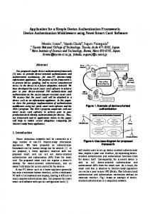
The equipment layout is described in Figure 1. It consists of two treadles to detect the wheel passage and two WFD detectors mounted in a cross layout. This allows the optimal detection of wheel flats present in diametrically opposite position (around 1.5 m of distance for standard wheels).
around 1.8 m (3 tie spans)
WFD1
DRT sensor
DRT2 BUNGALOW
DRT1
BJ DRT1
WFD2 BJ WFD1
BJ DRT2
WFD sensor
CENTRAL UNIT CPU
BJ WFD2
Power Supply Treatment Blocks
max 50 m
Figure 1. Layout of the GETS WFD equipment (left) and a partial view of the trackside mounted equipments (right).
The treadles are the new GETS DRT that are absolutely insensitive to rail vibrations and electromagnetic interference; their use is necessary to locate correctly the various wheels. The WFD detectors are made of a special clamp with a leaf spring that pre-loads a small aluminium block on which a short length of piezoelectric cable is mounted (Figure 2). The great advantage in the use of the piezocable is that it is sensitive to vibrations in all directions; the longitudinal vibrations are, more specifically, less damped with the distance and therefore this increases the detectability of the defects.
Figure 2. Cross-section of the WFD clamp and sensor (left) and a view of the clamp mounted (right). The leaf spring is designed to prevent the detach of the piezocable from the surface under up to 1000 g vertical accelerations.
All the electronics, developed specifically by GETS for this project, is certified in the typical railway extended range of temperatures and vibrations; as the equipment is not intended for safety purposes, actually the SIL level [11] is set to zero but, under request, can be properly increased. The WFD concept is, in principle, independent on the track details and the clamp can be adapted to any kind of metric (UIC) or English (BS or AREA) rail. Except for the power supply, that is no more a problem nowadays, the system can be used in any railway environment and therefore no problems are forecast for the operation in any country also thanks to the GE extensive customer service and support structure throughout the world.
3.3
System verification through measurements with known defects
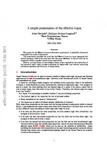
In November, 1998, a specific test campaign has been conducted to verify the correct functionality of the whole system. Figure 3 shows the sketch of the train used in that circumstance, with a lot of artificially made defects. The signal processing techniques described later leads to the results shown in figure 4.
Viareggio
30
30
45
15
15
Lucca
Figure 3. Test train used in the 1998 Nozzano test campaign. The numbers are the length of artificial flats made with a hand grinder.
Figure 4. Results for 70 km/h test run with a 15 mm wheel flat (top left) and a non-defective wheel (top right); test train running at 90 km/h with a 45 mm wheel flat (bottom left) and without defects (bottom right). Note that in the latter case the results are influenced by adjacent defective wheelsets.
3.4
Processing algorithm and defect management software
The results from the Nozzano test campaign allowed to confirm the validity of the principle and to identify the optimal range of frequency analysis. On the basis of the signals collected an original signal processing procedure was developed that allowed to identify correctly the defects rejecting at same time false and spurious signals. The procedure is based on the principle that a wheel flat generates a series of peaks that are the real characteristics of this abnormal wheel tread wear. The algorithm looks therefore at the repetitions of the impacts checking that a) at least 4 impacts exists, to prevent the recognition of false defects, and b) that the overall behaviour of the series of impacts is correct, i.e. the magnitude of the impacts decreases leaving the bogie area and the interval between the peaks is reasonably constant. The procedure includes filtering, Hilbert transforms, unbiased autocorrelation and power spectral density estimation, leading to a single figure that can be easily compared to a set of predefined thresholds selected by the end user. The developed procedure proved to be particularly stable and robust, and led to a number of false detection lower than 0.5 ‰, a certainly very good figure that can nevertheless improved with operation and experience.
4.
APPLICATION PROCEDURES
CONSIDERATIONS
AND
DEFECT
MANAGEMENT
As introduced in paragraph 2.1, the number of WFD equipments should be quite high in highly interconnected networks. This consideration is particularly evident in those situations where some kinds of rolling stock always run on a certain line and go to maintenance workshops very rarely for scheduled overhaul operations.
While for extremely long and “simple” railway lines, for example those connecting a mine to a port, a very expensive and complete device capable to detect any kind of defects on wheel treads is particularly advisable, a simplified equipment can be potentially very useful for interconnected networks, especially if its cost is 10 or 20 times lower than that of a general and complete system. A simple analysis of the traffic running in a particular country could lead to a rough estimation of the need of several tens of these equipments. Although it is greatly welcome the possibility to install the new equipment as turnkey systems, an important consideration must be made on the real detection of defects. The philosophy of the thresholds setting largely depends in fact on the railway administration policy. It was found during previous studies that the chord of the flat does not give an absolute indication of the gravity of the stresses introduced in the wheel/rail system. The “freshness” of the flat seems much more important; for example, by looking at the time histories recorded in Nozzano it comes out soon that there are no large differences between the signals generated by the various wheel flats, the were made the day before the tests and that had run no more than 100 km before starting the test runs. On the basis of the findings, the railway administrations should change the generalised concept that the size of the flat is directly related to the forces, and they should move to the more correct concept that only the measurement of rail vibrations can give a reasonable estimation of the negative effect of the flats. After some studies on neural networks and fuzzy logic systems, a more traditional cost-based approach was used. It is based on the hypothesis that the maximum number of detected error must fall in a well defined range, as • a too low number of detected defects can induce in the railway administration the thought that the equipment is malfunctioning, or • a too high number of detected defects can lead the railway administration to consider the outputs of the system not very reliable. In both the cases the system is likely to be turned off, giving in the first case no useful information on the real wheels health state and in the second case a too high number of alerts that can not be handled, for example, for traffic and workshop repair workload reasons. The steps to get the full operations are therefore the following: • the system is installed and acquires a certain number of trains that can be considered meaningful of the average rail traffic; • an initial set of threshold of different gravity, from alert to alarm, is automatically set on the basis of a statistical processing of the damage figures obtained on the initial set of trains; • the system is normally operated and, at regular intervals pre-determined by the railway administration, a new set of thresholds is calculated, by censoring meaningless data and by using, in principle, the concept of moving average. This last concept is clear when supposing that, with the extensive use of WFD systems, the percentage of circulating wheels with a flat decreases to a physiological and hopefully very low level. It would be wrong in principle, other than time consuming, to use in the average the whole history of the recordings. It could be wondering why such a complicated procedure is needed. The answer is that any track is different in terms of rail profile and of railpad, sleeper and ballast behaviour. An absolute calibration of the WFD system is therefore impossible and the depicted procedure allows the best system response leaving, moreover, ample margins of improvement in the system operation based on the customer needs.
5.
CONCLUSIONS
Different billing system are being used throughout Europe to charge the slot fee to the Train Operators but since now the impact of the train on the infrastructure maintenance cost has shown to be very difficult to be analysed, identified and correctly charged. In principle there are two main different reasons of application for wheel flat detection in this new business model. On the infrastructure side there is the strong need to identify wheel flats on trains running over the infrastructure affecting the maintenance of the wayside equipment in order to allocate correctly the costs and to cover them by a differentiation of slots fee and to warn on real time base those trains that are running at danger. On the Train Operator side there is again the need to check the fleet for safety reasons and to gain better slot fees in the light of what was said before. Especially in case of freight trains a wheel flat detection made in particular points under the Train Operator control and able to activate the train maintenance shop in the proper way seems to make a lot of sense as on-board systems look extremely not applicable. The Wheel Flat Detector available from GETS satisfy these requirements with a very high performance to cost ratio allowing to install a large number of equipments with low investments and optimum results.
6.
References
[1] O.R.E. B110/Rp.1/E, “Development of an acoustic device for the detection of wheel flats of a certain size”. Utrecht, 1968. [2] Ver, I.L., Ventres, C.S. and Myles, M.M., “Wheel/rail noise-part III: impact noise generation by wheel and rail discontinuities”, J. Sound Vibr., 1976, 46(3), 395-417. [3] Ahlbeck, D.R. “An investigation of impact loads due to wheel flats and rail joints”. Proceedings of ASME Winter Annual Meeting, Chicago, Illinois, 1980, 1-10. [4] Wiriyachai, A., Chu, K. and Garg, V.K., “Bridge impact due to wheel and track irregularities”. J. Engng. Mech. Div., 1982, Vol. 108, No. EM4, 648-667. [5] Kobayashi, M. and Naito, T., “Vibration and noise of model wheel due to tread roughness”, JRRI Quarterly Reports, 1983, Vol. 24(3), 131-132. [6] Raymond, G.P., “Track support must be right if concrete sleepers are to survive”, Railway Gazette International, July 1984, 528-530. [7] Fukuda, H., Sasama, H. and Tanabe, S., “Studies for the use of acoustic diagnosis in the railways”. JRRI Quarterly Reports, 1986, Vol. 27(4), 131-135. [8] Williams, S., Ahlbeck, D. and Harrison, H., “Railroad bearing performance under the wheel impact load environment”, Proceedings of the ASME Winter Annual Meeting, Boston, Massachusetts, 1987, 1-7. [9] Kaku, J. and Yamashita, M., “ Impact noise from railroads”. J. Sound Vibr., 1988, 120(2), 333-337. [10] Kumagai, N., Ishikawa, H., Haga, K., Kigawa, T., and Nagase, K., “Factors of wheel flats occurrence and preventive measurements”, Wear, 1991, 144, 277-287. [11] CENELEC 50126, 50128, 50129.