materials Article
Effects of Laser Power Level on Microstructural Properties and Phase Composition of Laser-Clad Fluorapatite/Zirconia Composite Coatings on Ti6Al4V Substrates Chi-Sheng Chien 1,2 , Cheng-Wei Liu 3 and Tsung-Yuan Kuo 3, * 1 2 3
*
Department of Orthopaedics, Chimei Foundation Hospital, Tainan 710, Taiwan;
[email protected] Department of Electrical Engineering, Southern Taiwan University of Science and Technology, Tainan 710, Taiwan Department of Mechanical Engineering, Southern Taiwan University of Science and Technology, Tainan 710, Taiwan;
[email protected] Correspondence:
[email protected]; Tel.: +886-6-2533131 (ext. 3000)
Academic Editor: Jonathan Phillips Received: 28 February 2016; Accepted: 11 May 2016; Published: 17 May 2016
Abstract: Hydroxyapatite (HA) is one of the most commonly used materials for the coating of bioceramic titanium (Ti) alloys. However, HA has poor mechanical properties and a low bonding strength. Accordingly, the present study replaces HA with a composite coating material consisting of fluorapatite (FA) and 20 wt % yttria (3 mol %) stabilized zirconia (ZrO2 , 3Y-TZP). The FA/ZrO2 coatings are deposited on Ti6Al4V substrates using a Nd:YAG laser cladding system with laser powers and travel speeds of 400 W/200 mm/min, 800 W/400 mm/min, and 1200 W/600 mm/min, respectively. The experimental results show that a significant inter-diffusion of the alloying elements occurs between the coating layer (CL) and the transition layer (TL). Consequently, a strong metallurgical bond is formed between them. During the cladding process, the ZrO2 is completely decomposed, while the FA is partially decomposed. As a result, the CLs of all the specimens consist mainly of FA, Ca4 (PO4 )2 O (TTCP), CaF2 , CaZrO3 , CaTiO3 and monoclinic phase ZrO2 (m-ZrO2 ), together with a small amount of θ-Al2 O3 . As the laser power is increased, CaO, CaCO3 and trace amounts of tetragonal phase ZrO2 (t-ZrO2 ) also appear. As the laser power increases from 400 to 800 W, the CL hardness also increases as a result of microstructural refinement and densification. However, at the highest laser power of 1200 W, the CL hardness reduces significantly due to the formation of large amounts of relatively soft CaO and CaCO3 phase. Keywords: fluorapatite; zirconia; laser cladding; laser power; composite coating
1. Introduction Biomedical implants typically comprise a thin bioceramic coating deposited on a titanium (Ti) alloy substrate [1–3]. Of the various coating materials available, hydroxyapatite (Ca10 (PO4 )6 (OH)2 ; HA) is one of the most commonly used since it has the same chemical composition and crystallographic structure as the apatite of living bones, and hence promotes early bonding between the implant and surrounding tissue [4–7]. HA coatings are generally deposited using a plasma spraying technique due to its short operation time, high accumulation rate, low processing cost, and low heat input. However, HA is intrinsically brittle, and hence the as-sprayed HA coatings generally have poor adhesion with the Ti substrate [8]. Moreover, under high temperature plasma spraying, the HA decomposes into impurities and low-crystallinity phases (e.g., tricalcium phosphate (Ca3 (PO4 )2 ), tetracalcium phosphate (Ca4 (PO4 )2 O), and calcium oxide (CaO)). These phases cause the coating to
Materials 2016, 9, 380; doi:10.3390/ma9050380
www.mdpi.com/journal/materials
Materials 2016, 9, 380
2 of 14
delaminate or flake, and can therefore lead to various medical disorders [9]. Furthermore, the HA coating and Ti substrate have very different thermal expansion coefficients. Consequently, significant residual stress is formed at the interface between the coating and the substrate during the spraying process [9]. This residual stress prompts premature coating degradation and can lead to implant failure after long-term imbedding in the human body. As a result, the need for alternative coating materials with improved structural stability under high temperature conditions has emerged as a pressing concern in recent decades. Fluorapatite (Ca10 (PO4 )6 (F)2 ; FA) has a similar level of biological activity and biocompatibility in the human body as HA. However, FA has better thermal and chemical stability, and therefore reduces the risk of pyrolysis [10–13]. Furthermore, FA has a slow bio-resorption rate, and thus promotes bone fixing and bone ingrowth [14,15]. As a result, FA has attracted significant interest as a possible substitute for HA in biomedical implant applications [16–18]. Many studies have shown that the mechanical properties and biological performance of biomedical coating materials can be enhanced through the addition of secondary phases such as zirconia (ZrO2 ) or alumina (Al2 O3 ) [19–26]. Among these phases, ZrO2 is a particularly attractive choice due to its relatively high mechanical strength and fracture toughness [23–26]. The excellent mechanical, electrical, thermal and optical properties of zirconia ceramics render them useful for many structural and functional applications [27–30]. In the biomedical field, yttria-stabilized tetragonal zirconia (Y-TZP) is widely used for dental restoration work due to its high biological safety and good hydrothermal stability [31]. Various studies have shown that 3 mol % yttria (3Y-TZP) provides an ideal stabilizing effect for zirconia [27,32]. However, even though FA is known to be more thermally and chemically stable than HA, the literature contains little information regarding the mechanical and biological properties of FA coatings mixed with ZrO2 [4,23,24,31]. Moreover, of those studies which have been performed, the coatings are generally prepared using sintering or plasma spraying techniques. In contrast to such methods, laser beams have high coherence and directionality, and thus have the potential to generate strong metallurgical bonds between the bioceramic coating layer and the substrate [33–37]. Consequently, the present study investigates the microstructural properties and phase composition of composite FA coatings containing 20 wt % yttria (3 mol %) stabilized zirconia (ZrO2 , 3Y-TZP) deposited on Ti6Al4V substrates using a laser-cladding technique. As in previous studies by the present group [38–40], the laser cladding process is performed using an Nd:YAG laser system. In laser cladding processes, the microstructural properties and phase composition of the coatings are significantly affected by three experimental parameters, namely the specific energy (Es = P/(V ˆ D), P: power; V: travel speed; D: laser beam diameter), the laser power density (LPD = P/(πD2 /4)) and the interaction time (t = D/V)). In the present study, the cladding process is performed using three different settings of the laser power and travel speed, namely 400 W/200 mm/min, 800 W/400 mm/min, and 1200 W/600 mm/min, respectively. In other words, the laser-power/travel-speed (P/V) ratio is equal to 2:1 in all of the cladding trials. Moreover, the laser spot diameter is equal to 3 mm (approximately) in every case. Consequently, the specific energy is a constant in the present study. By contrast, the laser power density increases as the laser power is increased from 400 W to 1200 W. Finally, the interaction time reduces as the travel speed increases. 2. Experiments The cladding trials were performed using Ti6Al4V alloy plates with dimensions of 100 mm ˆ 60 mm ˆ 3.8 mm and the chemical composition shown in Table 1. The FA was prepared using Ca3 (PO4 )2 (β-TCP, β-tricalcium phosphate) and CaF2 (Sigma-Aldrich, St. Louis, MO, USA) powders in accordance with the solid state reaction 3Ca3 (PO4 )2 + CaF2 Ñ Ca10 (PO4 )6 F2 [41]. Briefly, the powders were mixed in a stoichiometric molar ratio of 3:1 and milled with ZrO2 balls in ethanol for 48 h. After drying, the powder was compacted and heated at 1000 ˝ C for 3 h in air to form solid FA cylinders. The cylinders were then ground into powder and reinforced with 20 wt % commercial ZrO2
Materials 2016, 9, 380
3 of 14
powder (3 mol % Y2 O3 , EE-TEC Inc., Zhongli, Taiwan). Prior to the reinforcement process, the atomic Materials 2016, 9, 380 3 of 14 Materials 2016, 9, 380 14 structures of the FA (JCPDS 15-0876) and ZrO2 (3Y-TZP, JCPDS 49-1642) powders were examined3 of using XRD (Figure 1). No separate peak was detected (i.e., the XRD patterns of ZrO2 (3Y-TZP) and atomic structures of the FAyttria (JCPDS 15-0876) and ZrO 2 (3Y-TZP, JCPDS 49-1642) powders were atomic structures of the FA) are (JCPDS 15-0876) and ZrO 2 (3Y-TZP, JCPDS 49-1642) powders were TZP (tetragonal ZrO , t-ZrO very similar). The FA/ZrO powder was mixed with a polyvinyl 2 2 2 detected (i.e., the XRD patterns of examined using XRD (Figure 1). No separate yttria peak was examined using XRD (Figure 1). No separate yttria peak was detected (i.e., the XRD patterns of alcohol ((Cand O)n )(tetragonal in a 3:1 ratio (wt %) and stirred until a slurry-like consistency was obtained. 2 H4TZP ZrO2 binder (3Y-TZP) ZrO 2, t-ZrO2) are very similar). The FA/ZrO2 powder was mixed ZrO2 (3Y-TZP) and TZP (tetragonal ZrO2, t-ZrO2) are very similar). The FA/ZrO2 powder was mixed Aswith shown in Figure alcohol 2, the Ti6Al4V substrates used in the present were milled two slots a polyvinyl binder ((C 2H4O)n) in a 3:1 ratio (wt %)study and stirred until with a slurry-like with a polyvinyl alcohol binder ((C2H4O)n) in a 3:1 ratio (wt %) and stirred until a slurry-like (each with a size of 52 mm ˆ 44 mm ˆ 0.8 mm). The FA/ZrO + binder slurry was placed in each consistency was obtained. As shown in Figure 2, the Ti6Al4V substrates used in the present study consistency was obtained. As shown in Figure 2, the Ti6Al4V 2substrates used in the present study slotwere andmilled the excess using a stainless The substrate was then dried in withquantity two slotsremoved (each with a size of 52 mmsteel × 44scraper. mm × 0.8 mm). The FA/ZrO 2 + binder were milled with two slots (each with a size of 52 mm × 44 mm × 0.8 mm). The FA/ZrO2 + binder ˝ C for an slurry oven at 100 min under atmospheric conditions. Finally, specimens laserThe clad was placed in30 each slot and the excess quantity removed usingthe a stainless steelwere scraper. slurry was placed in each slot and the excess quantity removed using a stainless steel scraper. The substrate was then dried in an oven at 100 °C for 2500 30 min under atmospheric conditions. Finally, the using an Nd:YAG laser system (ROFIN CW025, W; Rofin Sinar Technologies Inc., Hamburg, substrate was then dried in an oven at 100 °C for 30 min under atmospheric conditions. Finally, the specimens were laser using an Nd:YAG system (ROFINthe CW025, 2500 W; Rofin Germany) operating in a clad continuous-wave mode.laser For each specimen, cladding process was Sinar limited specimens were laser clad using an Nd:YAG laser system (ROFIN CW025, 2500 W; Rofin Sinar Inc., Hamburg, Germany) operating in a continuous-wave mode. For each specimen, to aTechnologies single laser line scan. Technologies Inc., Hamburg, Germany) operating in a continuous-wave mode. For each specimen, the cladding process was limited to a single laser line scan. the cladding process was limited to a single laser line scan. Table 1. Chemical composition (wt %) of Ti6Al4V substrates. Table 1. Chemical composition (wt %) of Ti6Al4V substrates. Table 1. Chemical composition (wt %) of Ti6Al4V substrates. AlAl V V OO FeFe C C N N H H Ti Ti
Al V O Fe C N H Ti 4.24 0.152 0.152 0.16 0.16 0.017 0.0170.0080.008 0.0006 Balance 4.24 0.0006 Balance 6.1 4.24 0.152 0.16 0.017 0.008 0.0006 Balance
6.16.1
Figure 1. XRD patterns of coating powders: FAZrO and (3 ZrO 2 (3 mol % yttria (3Y-TZP), partially Figure 1. XRD patterns of coating powders: FA and mol % yttria partiallypartially stabilized Figure 1. XRD patterns of coating powders: FA and 2 (3 mol %(3Y-TZP), yttria (3Y-TZP), 2 ZrO stabilized with 3 mol % Y2O3). with 3 mol %with Y2 O33 ).mol % Y2O3). stabilized
Figure 2. Schematic illustration of Ti6Al4V substrate (unit: mm). Figure Schematicillustration illustrationof of Ti6Al4V Ti6Al4V substrate substrate (unit: Figure 2. 2.Schematic (unit:mm). mm).
Materials 2016, 9, 380
4 of 14
Materials 2016, 9, 380
4 of 14
As stated above, the cladding trials were performed using laser powers (P) and travel speeds (V) As 2016, stated above, 800 the W/400 claddingmm/min, trials wereand performed using mm/min. laser powers (P)laser and spot traveldiameter speeds of 400Materials W/200 mm/min, 1200 W/600 The 9, 380 4 of 14 was (V) of 400 W/200 mm/min, 800 W/400 mm/min, and 1200 W/600 mm/min. The laser spot diameter equal to approximately 3 mm in every case. Consequently, the specific energy (Es = P/(D ˆ V)) for equal to approximately 3 mm2in every case.performed Consequently, the specific energy (Es= = P/(πD P/(Dspeeds × 2V)) As stated above,tothe were using laser powers (P) and travel eachwas coating was equal 40 cladding J/mm . trials Furthermore, the laser power densities (LPD /4)) for 2/4)) for each coating was equal to 40W/400 J/mm2mm/min, . Furthermore, the laser power densities (LPD = P/(πD (V) of 400 W/200 mm/min, 800 and 1200 W/600 mm/min. The laser spot diameter the three cases were 5.66, 11.32 and 16.98 kW/cm2 , respectively. Finally, the interaction times (t = D/V) 2, respectively. Finally, the interaction times for three were 5.66,3 11.32 16.98 kW/cm wasthe equal to cases approximately mm inand every case. Consequently, the specific energy (Es = P/(D × V)) were 0.9, 0.45 and 0.3 s, respectively. The laser beam was guided to the workstation by an optical fiber (tfor = D/V) 0.9,was 0.45equal and 0.3 The laser the beam waspower guided to the workstation by2/4)) an each were coating to s, 40respectively. J/mm2. Furthermore, laser densities (LPD = P/(πD withoptical a corefiber diameter of 600 µm and a focal length of 120 mm. The cladding process was performed a core diameter of 600 µm and kW/cm a focal 2length of 120 mm. The cladding processtimes was for the threewith cases were 5.66, 11.32 and 16.98 , respectively. Finally, the interaction ˝ laser incident angle and a 15 mm in anperformed Ar-shielded atmosphere (Ar flow rate: 25 L/min) with a 5 in an Ar-shielded atmosphere (Ar flow rate: 25 L/min) with a 5° laser incident angle and (t = D/V) were 0.9, 0.45 and 0.3 s, respectively. The laser beam was guided to the workstation by an positive length. The experimental setup is shown in Figure 3. aoptical 15 defocus mmfiber positive defocus length. The experimental setup is shown in Figure 3. with a core diameter of 600 µm and a focal length of 120 mm. The cladding process was performed in an Ar-shielded atmosphere (Ar flow rate: 25 L/min) with a 5° laser incident angle and a 15 mm positive defocus length. The experimental setup is shown in Figure 3.
(a)
(b)
Figure 3. (a) Schematic illustration of Nd-YAG laser cladding system which was controlled by the
Figure 3. (a) Schematic illustration of Nd-YAG laser cladding system which (a) (b) was controlled by the computer numerical control (CNC); and (b) photograph of experimental setup. computer numerical control (CNC); and (b) photograph of experimental setup. Figure 3. (a) Schematic illustration of Nd-YAG laser cladding system which was controlled by the
The microstructures of the(CNC); clad specimens were observed using SEM (JEOL JSM-6390LV, JEOL computer numerical control and (b) photograph of experimental setup. Ltd., Tokyo, Japan). In the phase were compositions examined using SEM and EDS. The microstructures of addition, the clad specimens observedwere using SEM (JEOL JSM-6390LV, JEOL Ltd., Moreover, the various phases identified XRD (Cu using Kα using radiation, Rigaku D/Max Ш.V, The microstructures of phase thewere clad specimensusing were observed SEMSEM (JEOL JSM-6390LV, JEOL the Tokyo, Japan). In addition, the compositions were examined and EDS. Moreover, −1. Rigaku Ltd.,were Tokyo, Japan) with 2θ scanning range of 20°~70° and a scanning of and 2° Ltd., min Ltd., Tokyo, Japan). In addition, the phase compositions were examined using SEM EDS. various phases identified usinga XRD (Cu Kα radiation, Rigaku D/Max III.V,rate Rigaku Tokyo, Finally, the hardness of the coatings was determined using a micro-Vickers hardness tester under a ˝ ˝ ˝ ´ 1 Moreover, the various phases were identified using XRD (Cu Kα radiation, Rigaku D/Max Ш.V, Japan) with a 2θ scanning range of 20 ~70 and a scanning rate of 2 min . Finally, the hardness of maximum indentationJapan) load ofwith 300 g. Rigaku Ltd., a 2θ scanning range of 20°~70° and a scanning rate of 2° min−1. the coatings was Tokyo, determined using a micro-Vickers hardness tester under a maximum indentation Finally, the hardness of the coatings was determined using a micro-Vickers hardness tester under a load3.ofResults 300 g. Discussion maximumand indentation load of 300 g.
3. Results and Discussion 3.1. Morphology and Microstructure of Weld Beads 3. Results and Discussion
Figure 4and presents cross-sectional optical 3.1. Morphology Microstructure of Weld Beadsmicroscope (OM) images of the coating layers (CLs)
3.1. Morphology and Microstructure of Weld Beads and transition layers (TLs) of the three laser-clad specimens. As shown, for a constant Es, the depth, Figure 4 presents cross-sectional optical microscope (OM) the (CLs) width and depth/width ratio (i.e., aspect ratio) ofmicroscope the TL all increase with anof increasing laserlayers power(CLs) (see and Figure 4 presents cross-sectional optical (OM)images images of thecoating coating layers transition layers (TLs) of the three laser-clad specimens. As shown, for a constant Es, the depth, also 2). Inlayers addition, cracks evident withinspecimens. the TLs of As theshown, specimens higher laserwidth andTable transition (TLs) of theare three laser-clad for aprepared constantatEs, the depth, and powers depth/width (i.e., aspect ratio)ratio) of the TLTL allof increase with anincreasing increasing laser power of 800 Wratio and 1200 W, respectively. The severity the cracks increases with increasing power. width and depth/width ratio (i.e., aspect of the all increase with an laser power (see (see also Table In addition, cracks areevident evidentwithin within the prepared at higher laser laser also Table 2). In2).addition, cracks are the TLs TLsofofthe thespecimens specimens prepared at higher powers of W 800and W and 1200 respectively.The The severity severity of increases withwith increasing power. powers of 800 1200 W,W, respectively. ofthe thecracks cracks increases increasing power.
Figure 4. Optical microscope images of weld beads in fluorapatite (FA)/ZrO2 laser-clad specimens: (a) 400 W, 200 mm/min; (b) 800 W, 400 mm/min; and (c) 1200 W, 600 mm/min. (Note: CL denotes coating and TL denotes transition Figure layer 4. Optical microscope images oflayer). weld beads in fluorapatite (FA)/ZrO2 laser-clad specimens:
Figure 4. Optical microscope images of weld beads in fluorapatite (FA)/ZrO2 laser-clad specimens: (a) 400 W, 200 mm/min; (b) 800 W, 400 mm/min; and (c) 1200 W, 600 mm/min. (Note: CL denotes (a) 400 W, 200 mm/min; (b) 800 W, 400 mm/min; and (c) 1200 W, 600 mm/min. (Note: CL denotes coating layer and TL denotes transition layer). coating layer and TL denotes transition layer).
Materials 2016, 9, 380
5 of 14
Table 2. Depth-to-width ratio of TL in FA/ZrO2 specimens prepared using different laser powers. Sample
400 W/200 mm/min
800 W/400 mm/min
1200 W/600 mm/min
Depth (mm) Width (mm) Depth/Width Ratio
1.1 2.5 0.44
1.8 2.9 0.62
2.0 3.1 0.65
Given the same laser spot size and thermal diffusivity of the substrate, the size and shape of the weld fusion zone (i.e., weld bead) formed in the laser cladding process depends on the laser power density (LPD). For a low LPD, the weld fusion zone tends to be shallow and bowl-shaped. By contrast, for higher LPDs, the fusion zone is deeper and has a higher aspect ratio [42]. In the present study, even though the LPD increases with an increasing laser power, the specific energy, Es, is fixed. Thus, it seems reasonable to assume that the weld fusion zone should have a similar profile for all three specimens. However, in maintaining a constant Es, the laser travel speed is increased proportionally with increasing laser power. In practice, the laser speed also affects the shape of the weld bead. Thus, as shown in Figure 3, the weld bead profile changes with a changing LPD despite the constant Es in every case. Previous studies have shown that if the laser cladding parameters are not properly controlled, cracks are readily formed in the coating as a result of the thermal expansion mismatch between the coating and the substrate and relatively low toughness of the coating material [43]. As shown in Figure 4, cracks were not formed in any of the CLs. However, for the specimens prepared using laser powers of 800 W and 1200 W (i.e., a higher travel speed, heating rate and cooling rate), cracking occurred in the TL (see Figure 4b,c). The formation of these cracks is closely related to the residual stress generated during the cladding process [44]. Moreover, the stress increases with an increasing heating and cooling rate. The OM images in Figure 4b,c show that the cracks in the two specimens initiate within the TL, i.e., they do not spread from the CL. It is therefore concluded that the thermal expansion mismatch between the CL and the TL plays no role in prompting crack formation in the TL. In other words, crack initiation is dominated by the thermal stress generated by the rapid cooling rate of the substrate. More specifically, for a higher laser power (a higher laser travel speed), the cooling rate is increased. Consequently, the thermal shock within the TL is enhanced, and hence the crack severity increases. Furthermore, under a higher power level, the weld zone size also increases. As a result, a larger shrinkage stress is induced, and thus crack formation is further enhanced. Notably, however, the OM images in Figure 4 show that crack formation can be controlled through an appropriate setting of the laser power and travel speed parameters. Figure 5 shows the surface microstructures of the CLs in the three laser-clad samples. It is seen that for all three samples, the coating has a fibrous-like morphology. Moreover, as the laser power increases, an increasing number of granular compounds are formed between the fibrous-like structures. The SEM images confirm the absence of microcracks in the CL. The lack of cracks is reasonable since the coefficients of thermal expansion (CTE) of FA and ZrO2 (3Y-TZP) (i.e., 9.1 ˆ 10´6 K´1 [45] and 10~12 ˆ 10´6 K´1 [46], respectively) are quite close to that of the Ti6Al4V substrate (8.8 ˆ 10´6 K´1 [47]) in comparison to commonly used bioceramic coatings in the past, HA (15 ˆ 10´6 K´1 [47]). Hence, only limited differential expansion between the CL and the TL occurs. The addition of ZrO2 particles with good mechanical strength and high fracture toughness further enhances the cohesive strength of the CL and suppresses microcrack formation. Therefore, the FA/ZrO2 -substrate CTE mismatch is less than that for a HA/ZrO2 -substrate system. Consequently, it can be inferred that the present FA/ZrO2 coatings have a better adhesive strength with the Ti6Al4V substrate than HA/ZrO2 coatings [8,29]. Figure 6 shows the interfacial microstructures of the CL and TL in the three specimens. The EDS analysis results (presented in Section 3.2) show that a significant diffusion of alloying elements occurs between the CL and TL. As a result, a strong metallurgical bond is formed between them [34]. The bonding strength of such an interface is greater than the mechanical bonding strength formed in general coating processes such as plasma spraying, sol-gel, and so on. Figure 7 presents SEM cross-sectional metallographs of the mid-section region of the CL in the various samples.
Materials 2016, 9, 380 Materials 2016, 9, 380 Materials 2016, 9, 380 Compared Materialswith 2016, 9,the 380 CL
6 of 14 6 of 14 6 of 14 structures 6 of 14
surface microstructures shown in Figure 5, the quantity of fibrous is with the CL surface microstructures shown in Figure 5, the quantity of fibrous structures is reduced. reduced. However, a large number of spherical and irregularly-shaped particles are observed. For the with the CL surface microstructures shown in Figure 5, the quantity of are fibrous structures is reduced. However, a large number of spherical and irregularly-shaped particles observed. For is the sample with the CL surface microstructures shown in Figure 5, the quantity of fibrous structures reduced. sample prepared using a low laser power (400 W), the microstructure contains many flower-like However, a large number of spherical and irregularly-shaped particles are observed. For the sample prepared using a low laser power (400 W), the microstructure contains many flower-like structures. However, a large number of spherical and irregularly-shaped particles are observed. For the sample prepared using a low laser power (400 W), microstructure contains many flower-like structures. structures. However, as the power increases, the flower-like structures are replaced with spherical-like However,using as the power structures are replaced with spherical-like prepared a low laser increases, power (400the W),flower-like the microstructure contains many flower-like structures. However, as the the power increases, the flower-like structures are replaced with spherical-like particles. In general, SEM images presented in Figures 6 and 7 show that the higherrate cooling particles. In general, the SEM images presented in Figures 6 and 7 show that the higher cooling However, as the power increases, the flower-like structures are replaced with spherical-like particles. In general, the SEM images presented in Figures 6 and 7 show that the higher cooling rate rate associated with an increased increased laserpower powerresults results significant microstructural refinement associatedInwith an laser in in significant microstructural refinement and and particles. general, the SEM images presented in Figures 6 and 7 show that the higher cooling rate associated with anCL. increased laser power results in significant microstructural refinement and densification of the densification of the CL. associated with an increased laser power results in significant microstructural refinement and densification of the CL. densification of the CL.
Figure 5. SEM metallographs CL surface in FA/ZrO 2 laser-clad specimens: (a) 400 W, 200 Figure 5. SEM metallographs of CLofsurface in FA/ZrO specimens: (a) 400 W, 200 mm/min; 2 laser-clad Figure 5.(b) SEM metallographs ofand CL(c)surface in600 FA/ZrO 2 laser-clad specimens: (a) 400 W, 200 mm/min; 800 W, 400 mm/min; 1200 W, mm/min. Figure 5. mm/min; SEM metallographs of CL surface in FA/ZrO2 laser-clad specimens: (a) 400 W, 200 (b) 800 W, 400 and (c) 1200 W, 600 mm/min. mm/min; (b) 800 W, 400 mm/min; and (c) 1200 W, 600 mm/min. mm/min; (b) 800 W, 400 mm/min; and (c) 1200 W, 600 mm/min.
Figure 6. SEM metallographs of CL/TL interface in FA/ZrO2 laser-clad specimens: (a) 400 W, 200
Figure 6. SEM metallographs of and CL/TL interface in in FA/ZrO 2 laser-clad specimens: (a) 400 W, 200 mm/min; 800 W, 400 mm/min; (c) interface 1200 W, 600 mm/min. Figure 6. SEM metallographs of interface FA/ZrO specimens: (a)200 400 W, 2 laser-clad Figure 6. (b) SEM metallographs of CL/TL CL/TL in FA/ZrO 2 laser-clad specimens: (a) 400 W, mm/min; (b) 800 W, 400 mm/min; and (c) 1200 W, 600 mm/min. 200 mm/min; (b)800 800 400 mm/min; (c) W, 1200 600 mm/min. mm/min; (b) W,W, 400 mm/min; and and (c) 1200 600W, mm/min.
Figure 7. SEM metallographs of mid-section region of cross sectional CL in FA/ZrO2 laser-clad Figure 7. SEM metallographs of mid-section region of cross sectional CL inmm/min. FA/ZrO2 laser-clad specimens: (a) 400 W, 200 mm/min; (b) 800 W, 400 mm/min; andsectional (c) 1200 W, Figure 7. SEM metallographs mid-section region of cross CL600 in FA/ZrO2 laser-clad specimens: (a) 400 W, 200 mm/min; (b) 800 W, 400 mm/min; and (c) 1200 W, CL 600 in mm/min. Figure 7. SEM metallographs ofofmid-section region of cross sectional FA/ZrO2 laser-clad specimens: (a) 400 W, 200 mm/min; (b) 800 W, 400 mm/min; and (c) 1200 W, 600 mm/min.
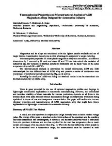
specimens: 400 W, 200Analysis mm/min; (b) 800 W, Coatings 400 mm/min; and (c) 1200 W, 600 mm/min. 3.2. Chemical(a) Composition of Laser-Clad 3.2. Chemical Composition Analysis of Laser-Clad Coatings 3.2. Chemical Composition Analysis of Laser-Clad Figure 8a presents an SEM image of theCoatings CL in the sample prepared using a laser power of 3.2. Chemical Composition Analysis ofimage Laser-Clad Coatings Figure 8a presents an SEM of the CL in for the globular sample prepared using laser power of 1200 Figure W. Figure 8b,c shows the EDS analysis particles using A andaa Blaser in Figure 8a presents an SEM image of the results CL in the sample prepared power 8a, of 1200 W. Figure 8b,c shows the EDS analysis results for mainly globularofparticles A and presence B in Figure 8a, respectively. As 8b,c shown in Figure 8b,ofanalysis particle A Ti and P. ofofTiP Figure presents an SEM image the CL results in consists the sample prepared using a laser power 1200 W. 1200 W.8aFigure shows the EDS for globular particles A The and B in Figure 8a, respectively.(Ti Asphosphides) shown in Figure 8b, particle A consists mainly of Ti andofP.the TheFApresence of TiP compounds [48] suggests afor partial thermal decomposition content in TiP the respectively. Asthe shown Figure 8b, particle A consists mainly ofATiand andBP.inThe presence of Figure 8b,c shows EDSinanalysis results globular particles Figure 8a, respectively. compounds (Ti phosphides) [48] suggests a partial thermal decomposition of the FA content in the CL during the high-temperature claddingaprocess, accompanied by thermal-induced melting and compounds (Ti phosphides) [48] suggests partial thermal decomposition of the FA content in the As shown in Figure 8b, particle Acladding consistsprocess, mainlyaccompanied of Ti and P.byThe presence of TiP compounds CL during the high-temperature thermal-induced melting and diffusion Ti from the substrate. cladding As the laser poweraccompanied increases, theby extent of FA decomposition and CL duringofthe high-temperature process, thermal-induced melting and (Ti phosphides) suggests a partial thermal of the FA content in the CL during diffusion of [48] Ti from the substrate. As thehence laserdecomposition power increases, the extent of FA decomposition and the Ti melting/diffusion also increases, and Ti phosphides of a greater size are formed, as shown diffusion of Ti from the substrate. As the laser power increases, the extent of FA decomposition and high-temperature cladding accompanied thermal-induced melting and diffusion of Ti from Ti Figure melting/diffusion alsoprocess, increases, and hence Tiby phosphides of a greater size of are formed, as shown in 7b,c. It is noted that the and present results are consistent with those Ye et al. [48], who Ti melting/diffusion also increases, hence Ti phosphides of a greater size are formed, as shown in Figure 7b,c. It is noted that the present results are consistent with those of Ye et al. [48], who the substrate. As the laser power increases, the extent of FA decomposition and Ti melting/diffusion showed number phosphides xPy) were formed when sintering Ti/FA (1:1) in Figurethat 7b,c.a Itlarge is noted that of theTipresent results(Ti are consistent with those of Ye et al. [48], who showed that large Ti number of Ti phosphides xPare y) were formed when in sintering also increases, andahence phosphides of a greater (Ti size formed, as shown Figure Ti/FA 7b,c. It(1:1) is noted showed that a large number of Ti phosphides (TixPy) were formed when sintering Ti/FA (1:1)
that the present results are consistent with those of Ye et al. [48], who showed that a large number of Ti phosphides (Tix Py ) were formed when sintering Ti/FA (1:1) composite powders under temperatures of 1100 ˝ C or 1200 ˝ C. In general, Ti phosphides can have a wide range of compositions, and it is thus difficult to reliably determine the exact composition of Tix Py by XRD analysis alone [49]. Notably, the
Materials 2016, 9, 380
7 of 14
Materials 2016, 9, 380 Materials 2016, 9, 380
7 of 14
7 of 14
composite powders under temperatures of 1100 °C or 1200 °C. In general, Ti phosphides can have a wide range of compositions, and it is thus difficult to reliably determine the exact composition of composite powders under temperatures of 1100 °C to or particle 1200 °C. B Inin general, phosphides have a EDS results presented in Figure 8c, corresponding FigureTi8a, show thatcan even under TixPy by XRD analysis alone [49]. Notably, the EDS results presented in Figure 8c, corresponding to range of compositions, andW, it is thus to reliably the exact composition of thewide maximum laser power of 1200 the CL difficult matrix still containsdetermine a large amount of fluoride. In other particle B in Figure 8a, show that even under the maximum laser power of 1200 W, the CL matrix TixPy the by XRD analysis [49]. Notably, the EDS to results presented in Figure corresponding to words, potential foralone FA residue or conversion fluoride still exists even8c, under high cladding still contains a large amount of fluoride. In other words, the potential for FA residue or conversion particle B in as Figure 8a, show that even under maximum laser power of 1200 W, the CL matrix temperatures, in high Section 3.3. the to fluoride stilldiscussed exists evenlater under cladding temperatures, as discussed later in Section 3.3. still contains a large amount of fluoride. In other words, the potential for FA residue or conversion to fluoride still exists even under high cladding temperatures, as discussed later in Section 3.3.
(a)
(b)
(c)
Figure 8. (a) SEM metallograph showing microstructure of CL in FA/ZrO2 specimen prepared using Figure 8. (a)(a) SEM metallograph showing microstructure of CL in FA/ZrO2 specimen(c) prepared using (b) P = 1200 W and V = 600 mm/min; (b) EDS analysis results for particle A in (a); and (c) EDS analysis P = 1200 W and V = 600 mm/min; (b) EDS analysis results for particle A in (a); and (c) EDS analysis results8.for B in (a). Figure (a)particle SEM metallograph showing microstructure of CL in FA/ZrO2 specimen prepared using results for particle B in (a). P = 1200 W and V = 600 mm/min; (b) EDS analysis results for particle A in (a); and (c) EDS analysis Figure presents results for9particle B inthe (a).EDS line scanning results for the individual alloying elements of the Figure29cladding presentslayer the EDS results for thespecimen individual alloyingusing elements of the FA/ZrO FA/ZrO nearline thescanning CL/TL interface in the prepared a laser power of 2 1200Figure W. It is seenthe that the Ca and F elements, i.e., the main decomposition components FA,ofare 9near presents the EDS line scanning results for the individual alloying elements the cladding layer CL/TL interface in the specimen prepared using a laser power ofof1200 W. It is confined almost entirely to the CL. Previous studies have shown that in the thermal decomposition FA/ZrO 2 cladding layer near the CL/TL interface in the specimen prepared using a laser power of seen that the Ca and F elements, i.e., the main decomposition components of FA, are confined almost of FA, either vaporized HFhave or forms fluoride [24]. Thus, decomposition the F content in of theFA, CL layer 1200 W. It isisCL. seenPrevious that the studies Caasand Fgas elements, i.e., the decomposition components of FFA, are entirely to Fthe shown that inmain the thermal is either most probably comes from the FA or fluoride, but requires further XRD analysis for confirmation confinedas almost entirely to the CL. Previous studies showninthat thermal vaporized HF gas or forms fluoride [24]. Thus, thehave F content the in CLthe layer mostdecomposition probably comes Section 3.3). vaporized The P and as O ions in the material haveThus, the ability diffuseinrapidly from of(see FA, F isor either HF gas or coating forms the F to content the CL from the FA fluoride, but requires further XRDfluoride analysis[24]. for confirmation (see Section 3.3).layer The P the CL to the TL due tofrom theirthe small and low activation energy. Nonetheless, as shown in Figure 9, most probably FAradii or fluoride, but to requires XRD analysis fortoconfirmation and O ions in thecomes coating material have the ability diffusefurther rapidly from the CL the TL due to some ions still remainP within is coating noted, however, that of the Ptoions produced in the (see Section 3.3). and O the ionsCL. in Itthe material havesome the rapidly their small radii andThe low activation energy. Nonetheless, as shown inability Figure 9, diffuse some ions still from remain FA decomposition process simply vaporize in the high-temperature cladding process [37–40]. the CL to the TL due to their small radii and low activation energy. Nonetheless, as shown in Figure 9, within the CL. the It isresults noted,presented however, that some P ions in the FA decomposition process Observing Figure 9, of it isthe seen that produced the distributions in the CL andin TL, some ions still remain within thein CL. It is noted, however, that some of theofPZr ions produced the simply vaporize in the high-temperature cladding process [37–40]. Observing the results presented in respectively, are roughly the same. In other words, given an addition of 20 wt % ZrO 2 to the FA FA decomposition process simply vaporize in the high-temperature cladding process [37–40]. Figure 9, it ismaterial, seen that the distributions in the CL andthe TL,CL respectively, roughly the same. cladding certain amount ofofZrZrremains despite theare temperature Observing the resultsa presented in Figure 9, it is seenwithin that the distributions of Zrhigh in the CL and TL, In other words, given an addition wt % aZrO theTiFA cladding a certain amount diffusion effect. Furthermore, theof TL20retains very high content; withmaterial, only a small amount of Ti of 2 to respectively, are roughly the same. In other words, given an addition of 20 wt % ZrO2 to the FA diffusingwithin to the the CL. CL Overall, thethe EDS results reveal thatdiffusion while significant diffusion of the Zr remains despite high temperature effect. Furthermore, thealloying TL retains cladding material, a certain amount of Zr remains within the CL despite the high temperature elements occurs between TL aand the amount CL, the alloying elementsto inthe the TL are basically similar to a very high effect. Ti content; withthe only small ofhigh Ti diffusing Overall, EDS of results diffusion Furthermore, the TL retains a very Ti content; withCL. only a small the amount Ti the composition of the substrate, while those in the CL are similar to that of the coating material. reveal that while significant diffusion of the alloying elements occurs between the TL and the CL, the
diffusing to the CL. Overall, the EDS results reveal that while significant diffusion of the alloying alloying elements the TL the are TL basically toalloying the composition while similar those intothe elements occurs in between and thesimilar CL, the elements of in the the substrate, TL are basically CLthe arecomposition similar to that of the coating material. of the substrate, while those in the CL are similar to that of the coating material.
Region of EDS line scanning Figure 9. Cont.
Region of EDS line scanning Figure 9. Cont. Figure 9. Cont.
Materials Materials2016, 2016,9,9, 380 380 Materials 2016, 9, 380
88of of14 14 8 of 14
Figure 9. EDS line scan results for Ca, P, O, Ti, F and Zr contents of CL and TL in FA/ZrO2 specimen Figure 9. EDS line scan results for Ca, P, O, Ti, F and Zr contents of CL and TL in FA/ZrO2 specimen Figure 9. EDS line P, mm/min. O, Ti, F and Zr contents of CL and TL in FA/ZrO2 specimen prepared using P =scan 1200results W andfor V Ca, = 600 prepared usingPP==1200 1200 W W and and V V == 600 600 mm/min. mm/min. prepared using
3.3. XRD Patterns of CL Surface 3.3. XRD Patterns of CL Surface 3.3. XRD Patterns of CL Surface Figure 10 shows the XRD patterns of the CL surfaces in the three specimens. For the 400 W Figure 10 shows the XRD patterns of the CL surfaces in the three specimens. For the 400 W sample, the 10 CLshows consists of FA, TTCP (tetracalcium 4(PO4)2O (JCPDS 25-1137), Figure themainly XRD patterns of the CL surfacesphosphate, in the threeCaspecimens. For the 400 W sample, the CL consists mainly of FA, TTCP (tetracalcium phosphate, Ca4(PO4)2O (JCPDS 25-1137), CaF2 (JCPDS 35-0816), 3 (JCPDS 35-0790), CaTiO3 (JCPDS 22-0153), 2 (monoclinic phase sample, the CL consistsCaZrO mainly of FA, TTCP (tetracalcium phosphate, Ca4m-ZrO (PO4 )2 O (JCPDS 25-1137), CaF2 (JCPDS 35-0816), CaZrO3 (JCPDS 35-0790), CaTiO3 (JCPDS 22-0153), m-ZrO2 (monoclinic phase ZrO22,(JCPDS JCPDS 35-0816), 88-2390) and a small amount of θ-Al 2O3 (JCPDS 23-1009). the 800 W specimen, the CaF CaZrO 35-0790), CaTiO 22-0153),For m-ZrO phase 3 (JCPDS 3 (JCPDS 2 (monoclinic ZrO2, JCPDS 88-2390) and a small amount of θ-Al2O3 (JCPDS 23-1009). For the 800 W specimen, the CL 2additionally contains (JCPDS CaCO 3 (JCPDS 47-1743) and a trace amount of ZrO , JCPDS 88-2390) and aCaO small amount37-1497), of θ-Al2 O (JCPDS 23-1009). For the 800 W specimen, the 3 CL additionally contains CaO (JCPDS 37-1497), CaCO 3 (JCPDS 47-1743) and a trace amount of t-ZrO 2 (tetragonal phaseCaO ZrO(JCPDS 2, JCPDS 80-0965). For3 the 120047-1743) W specimen, the CL contains large CL additionally contains 37-1497), CaCO (JCPDS and a trace amount of t-ZrO t-ZrO2 (tetragonal phase ZrO2, JCPDS 80-0965). For the 1200 W specimen, the CL contains large2 quantities of CaO, CaCO 3 and80-0965). TTCP, but lesser of CaTiO . Furthermore, thequantities quantity of of (tetragonal phase ZrO Forathe 1200amount W specimen, the3CL contains large 2 , JCPDS quantities of CaO, CaCO 3 and TTCP, but a lesser amount of CaTiO3. Furthermore, the quantity of t-ZrOCaCO 2 increases, while that of m-ZrO 2 and CaZrO 3 decreases. Notably, the XRD pattern also indicates CaO, and TTCP, but a lesser amount of CaTiO . Furthermore, the quantity of t-ZrO increases, 3 3 2 t-ZrO2 increases, while that of m-ZrO2 and CaZrO3 decreases. Notably, the XRD pattern also indicates the presence of trace2 amounts of 3several unknown compounds in the CL. Inindicates general, the XRD results while that of m-ZrO and CaZrO decreases. Notably, the XRD pattern also presence of the presence of trace amounts of several unknown compounds in the CL. In general, the XRD results indicate a greater tendency toward compound phase CL as the laser power is trace amounts of several unknown compounds in the CL. formation In general, in thethe XRD results indicate a greater indicate a greater tendency toward compound phase formation in the CL as the laser power is increased.toward compound phase formation in the CL as the laser power is increased. tendency increased.
Figure 10. XRD analysis results for CLs CLs of FA/ZrO FA/ZrO 2 specimens prepared using different laser Figure analysis results for CLs of FA/ZrO prepared using different laser powers. 2 specimens Figure10. 10.XRD XRD analysis results for of 2 specimens prepared using different laser powers. powers.
The FA powder used in the present study was prepared via a solid state reaction of Ca3 (PO4 )2 (TCP) and CaF2 at 1000 ˝ C for 3 h. However, in the cladding process, the FA reverts to Ca3 (PO4 )2 and
Materials 2016, 9, 380
9 of 14
CaF2 in accordance with Reaction (1) if the temperature remains sufficiently high for a sufficiently long period of time [23,31]. For example, Nasiri-Tabrizi and Fahami [23] reported that a partial decomposition of FA to Ca3 (PO4 )2 and CaF2 occurs at 900 ˝ C for 1 h in the presence of zirconia. However, at higher temperatures (i.e., greater than 1100 ˝ C), CaF2 transforms to CaO through hydrolysis, as shown in Reaction (2) [50]. Thus, the high CaO content in the CL of the present specimen prepared using a high laser power of 1200 W is most likely the result of the thermally-induced hydrolysis of CaF2 . Ca10 pPO4 q6 F2 Ñ 3Ca3 pPO4 q2 pTCPq ` CaF2 (1) CaF2 ` H2 O(g) Ñ CaO ` 2HF(g)
(2)
In high temperature processes, the decomposition of FA powder without oxide addition can be described by Reaction (3). (Note that Reaction (3) is equivalent to Reaction (1) + Reaction (2)). In other words, in high temperature processes, FA decomposes as TCP and CaO [24,50]. In the present study, ZrO2 is also added to the coating. The additional reactions which therefore take place under high density laser power irradiation are described by Reaction (4) below. Ca10 pPO4 q6 F2(s) ` H2 O(g) Ñ 3Ca3 pPO4 q2(s) pTCPq ` CaO(s) ` 2HF(g)
(3)
Ca3 pPO4 q2(s) pTCPq ` 2CaO(s) ` ZrO2(s) Ñ Ca4 pPO4 q2 O pTTCPq ` CaZrO3
(4)
Ben and Bouaziz [24] examined the decomposition of FA doped with ZrO2 , and showed that given sufficient time and temperature, the decomposed TCP and CaO react with the ZrO2 to produce TTCP and CaZrO3 . In addition, many researchers have analyzed the reaction between ZrO2 and CaO in accordance with Reaction (5) [4,24,29,51]. CaO(S) ` ZrO2(S) Ñ CaZrO3(S)
(5)
In the XRD patterns in Figure 10, a peak corresponding to the original ZrO2 powder (3Y-TZP, XRD pattern similar to t-ZrO2 ) is absent for the 400 W specimen. Moreover, only small quantities of ZrO2 are detected in the 800 W and 1200 W samples. In other words, most of the ZrO2 particles melt and undergo phase transformation during the laser cladding process. However, FA is still present in all three samples. Thus, it is inferred that even though the original FA powder melts completely during the laser-cladding process, the high thermal stability of the FA powder and the short residence time of the powder at high temperature result in only a partial decomposition of the FA to TTCP and CaO. However, as the laser power increases, the extent of FA decomposition also increases. Thus, for the specimens prepared using higher laser powers of 800 W and 1200 W, respectively, the intensity of the TTCP and CaO peaks in the XRD patterns increases. Under the high temperatures produced during the laser cladding process, the ZrO2 particles reside in a molten state and the diffusion of Ca ions into the ZrO2 particles is enhanced. Consequently, CaZrO3 is formed during cooling in accordance with Reaction (5) above. Furthermore, CaO is unstable and reacts with CO2 to form calcium carbonate (CaCO3 ) in air [31]. As the temperature increases, more of the original FA powder decomposes as CaO, and hence the quantity of CaCO3 increases. In addition, Al2 O3 is produced via the reaction between Al atoms diffused from the substrate and the coating material atoms or environmental O atoms. Finally, CaTiO3 is produced through a reaction between the decomposed or melted FA and the Ti6Al4V substrate. For the 400 W sample, the XRD pattern indicates the presence of both m-ZrO2 and CaZrO3 compounds. For the sample prepared with a higher power of 800 W, the intensity of the m-ZrO2 and CaZrO3 peaks increases and a trace amount of t-ZrO2 emerges. However, for the sample prepared using the highest power of 1200 W, the intensity of the t-ZrO2 peak increases, but that of the m-ZrO2 and CaZrO3 peaks decreases. In other words, the original ZrO2 (3Y-TZP) powder melts more completely under high-energy laser irradiation. During the cooling and solidification phase, an allotropic transformation of the ZrO2 compound takes place from the cubic phase (c-ZrO2 2370–2680 ˝ C (melting point)) to the tetragonal phase (t-ZrO2 , 1170 ˝ C–2370 ˝ C), and finally to the
Materials 2016, 9, 380
10 of 14
monoclinic phase (m-ZrO2 , room temperature–1170 ˝ C) [32]. For laser cladding at 400 W, the t-ZrO2 phase has sufficient time to transform to m-ZrO2 due to the lower cooling rate (i.e., the lower travel speed). As a result, the ZrO2 exists almost entirely in the monoclinic phase. However, for higher laser powersMaterials of 800 W and 1200 W, respectively, insufficient time exists for t-ZrO2 transformationto 2016, 9, 380 10 of 14 m-ZrO2 and consequently the quantity of t-ZrO2 increases while that of m-ZrO2 decreases. Notably, no allotropicintransformation of the ZrO2 compound placefinding from the cubic phase 2 c-ZrO2 is observed any of the XRD patterns in Figuretakes 10. This suggests that (c-ZrO the temperature 2370–2680 °C (melting point)) to the tetragonal phase (t-ZrO2, 1170–2370 °C), and finally to the required formonoclinic c-ZrO2 formation is not maintained for a sufficient length of time during the cooling phase (m-ZrO2, room temperature–1170 °C) [32]. For laser cladding at 400 W, the t-ZrO2 process, andphase hence quantity c-ZrO2 formed tootolow to becooling detected viathe XRD analysis. hasthe sufficient time of to transform to m-ZrO2isdue the lower rate (i.e., lower travel speed). AsRao a result, ZrO2 exists almost in the monoclinic However, for higher Ramachandra andthe Kannan [26] andentirely Nagarajan and Raophase. [51] showed that the laser CaO released powers of 800 W and 1200 W, respectively, insufficient time for t-ZrO2 transformationto during the sintering of HA/ZrO2 at temperatures of 1150 ˝ C exists and above stabilizes the m-ZrO2 via m-ZrO2 and consequently the quantity of t-ZrO2 increases while that of m-ZrO2 decreases. Notably, a solid solution reaction, and prompts the formation of t-ZrO . However, with the release of excess no c-ZrO 2 is observed in any of the XRD patterns in Figure 210. This finding suggests that the CaO through the further decomposition of FA, the solubility Ca in length ZrO2ofexceeds the temperature required for c-ZrO2 formation is not maintained for aof sufficient time during themaximum cooling process, hence the quantityisof formed c-ZrO2 formed is too low to betodetected via[52,53]. XRD analysis. solid solution range andand hence CaZrO in preference t-ZrO Heimann and 3 2 Ramachandra Rao and Kannan [26] and Nagarajan and Rao [51] showed that the CaO released Vu [52] showed that when CaO is added to HA/ZrO2 composite sintered samples, the surplus CaO is during the sintering of HA/ZrO2 at temperatures of 1150 °C and above stabilizes the m-ZrO2 via a effectively fixed by the reaction, ZrO2 , which acts as sink forofthe Ca2. 2+ ions. Consequently, solid solution and prompts theaformation t-ZrO However, with the release ofeither excess t-ZrO2 or CaO through the further decomposition of FA, the solubility of Ca in ZrO 2 exceeds the maximum solidformation CaZrO3 is formed. Furthermore, according to the ZrO2 -CaZrO3 phase diagram [54], the solution range and hence CaZrO 3 is formed in preference to t-ZrO2 [52,53]. Heimann and Vu [52] of CaZrO3 depends on the extent of CaO diffusion into ZrO2 . Hence, a fuller decomposition of showed that when CaO is added to HA/ZrO2 composite sintered samples, the surplus CaO is FA promotes the production CaZrO However, inthe the study, although the2 or quantity of 2+ ions. Consequently, 3 .acts effectively fixed by theof ZrO 2, which as a sink for Capresent either t-ZrO CaO increases significantly with an increasing laser that diagram of t-ZrO only CaZrO 3 is formed. Furthermore, according to the ZrO2power, -CaZrO3 phase [54], the formation of slightly. 2 increases CaZrO depends on extent of CaO diffusion into ZrO 2. Hence, a fuller decomposition of FA Furthermore, the 3quantity ofthe CaZrO reduces under the highest laser power of 1200 W. By contrast, 3 promotes the production of CaZrO3. However, in the present study, although the quantity of CaO the quantity of CaCO3 increases significantly with an increasing laser power. This feature suggests increases significantly with an increasing laser power, that of t-ZrO2 increases only slightly. that given a Furthermore, sufficientlythe high laserof energy, the tendency CaOlaser andpower CO2ofto1200 react and form CaCO3 is quantity CaZrO3 reduces under the of highest W. By contrast, the quantity CaCO 3 increases significantly with an increasing laser power. This feature suggests higher than that of CaOofand ZrO reacting to form CaZrO . However, further investigation is required 2 3 that given a sufficiently high laser energy, the tendency of CaO and CO 2 to react and form CaCO3 is to confirm this inference and to clarify the related underlying mechanisms. higher than that of CaO and ZrO2 reacting to form CaZrO3. However, further investigation is required to confirm this inference and to clarify the related underlying mechanisms.
3.4. Micro-Hardness Evaluation
3.4. Micro-Hardness Evaluation
Figure 11 shows the cross-sectional hardness profiles of the various specimens from the CL Figure 11 shows the cross-sectional hardness profiles the the various specimensFor from CL samples, (thickness approximately 0.2–0.3 mm) through the TL and of into substrate. allthe three (thickness approximately 0.2–0.3 mm) through the TL and into the substrate. For all three samples, the TL has athe higher than the which has a greater hardness the substrate. TL has hardness a higher hardness than CL, the CL, whichin in turn turn has a greater hardness than thethan substrate. Comparing Comparing the CL hardness values of the three samples, it is seen that the hardness increases from the CL hardness values of the three samples, it is seen that the hardness increases from 1100 HV 0.3 to 1300 HV 0.3 as the laser-cladding power is increased from 400 W to 800 W, but then 1100 HV0.3 to 1300 HV0.3 as the laser-cladding power is increased from 400 W to 800 W, but then reduces reduces to around 800 HV0.3 as the laser-cladding power is further increased to 1200 W. From to around 800 HV0.3 as the laser-cladding power is further increased to 1200 W. From inspection, the inspection, the CL hardness of the three specimens is around 2~3 times higher than that of the CL hardnessTi6Al4V of the substrate. three specimens is around 2~3 times higher than that of the Ti6Al4V substrate.
Figure 11. Cross-sectional hardness profiles of FA/ZrO2 specimens prepared using different laser
Figure 11. powers. Cross-sectional hardness profiles of FA/ZrO2 specimens prepared using different laser powers.
The hardness of laser-clad coatings is related to both their microstructural characteristics (e.g., porosity and density) and their phase constituents [41,43,55]. For the present samples, the CL microstructure exhibits a greater refinement and densification effect as the laser power (travel
Materials 2016, 9, 380
11 of 14
speed) increases (see Figure 6). Consequently, the hardness increases. The phase constituents of the CL can be ranked in order of decreasing hardness as ZrO2 > CaF2 > CaO > CaCO3 [56]. As shown in the XRD patterns in Figure 10, the sample prepared using a laser power of 1200 W has a high CaO and CaCO3 (low hardness) content. Thus, the microstructure-induced hardness enhancement is outweighed by the softening effect of the CaO and CaCO3 phases, and consequently a reduction in the CL hardness occurs. Chien et al. [57] showed that the average hardness of the CL formed in the laser cladding of pure FA on Ti6Al4V substrates was equal to 617 HV0.3 for a laser power of 740 W and 750 HV0.3 for a laser power of 1150 W. It is noted that these hardness values are significantly lower than those obtained in the present study. The laser source and laser cladding parameters are similar in both cases. Hence, it is inferred that the higher CL hardness of the present specimens is due to the addition of ZrO2 to the FA matrix. Kim et al. [41] prepared sintered FA samples containing 20 and 40 vol % ZrO2 powder, respectively, and found that the hardness increased with an increasing ZrO2 content. Ouyang et al. [43] used a laser-cladding process to deposit yttria partially stabilized ZrO2 (7 wt %) ceramic coatings doped with 2.5 wt % TiO2 on aluminum alloy substrates. The cladding layer was found to have a hardness of 1415~1575 HV0.1 . This value is greater than that observed for the present coatings. Kim et al. [41] conducted sintering trials using HA and FA powders doped with 20 vol % ZrO2 . The results showed that the FA-ZrO2 composites had a greater hardness (~8 GPa) than the HA-ZrO2 samples (~1 GPa). Various studies have attributed the greater hardness of laser-clad ZrO2 or ZrO2 composite coatings to the absence of porosity and a fine-grained structure [41,43]. However, the present results suggest that the hardness is actually determined by a competition process between the microstructural hardening effects and the phase composition softening effects. 4. Conclusions The present study has deposited composite coatings consisting of fluorapatite (FA) and 20 wt % yttria (3 mol %) stabilized zirconia (ZrO2 , 3Y-TZP) on Ti6Al4V substrates using a laser cladding process with laser powers and travel speeds of 400 W/200 mm/min, 800 W/400 mm/min, and 1200 W/600 mm/min, respectively. The experimental findings support the following main conclusions. 1.
2.
3.
4.
The depth, width and depth/width ratio of the TL increase with an increasing laser power (travel speed). For the 800 W and 1200 W specimens, cracks are formed in the TL due to the greater cooling rate and larger weld zone (i.e., greater shrinkage stress). However, no cracks are formed in the CL due to the addition of ZrO2 to the FA powder and the relatively small CTE mismatch between the FA/ZrO2 powders and the substrate. A significant diffusion of alloying elements occurs between the CL and the TL. As a result, a good metallurgical bond is formed between them. Overall, the alloying elements of the TL are close to the composition of the substrate, while the alloying elements of the CL are close to the composition of the coating material. The CL of the 400 W specimen consists mainly of FA, TTCP, CaF2 , CaZrO3 , CaTiO3 , m-ZrO2 and a small amount of θ-Al2 O3 . For the 800 W specimen, the CL also contains CaO, CaCO3 and trace amounts of t-ZrO2 . For the highest laser power of 1200 W, the CaO, CaCO3 and TTCP contents of the CL increase significantly. The t-ZrO2 content also increases. However, that of m-ZrO2 and CaZrO3 reduces. In general, the tendency to form composite phases increases as the laser power increases. For all of the specimens, the TL has a greater hardness than the CL. Moreover, the CL hardness is around 2~3 times higher than that of the Ti6Al4V substrate. As the laser power increases from 400 W to 800 W, the CL hardness increases due to a microstructural refinement and densification effect. However, under the highest laser power of 1200 W, the hardness reduces significantly due to the formation of CaO and CaCO3 phases with relatively low hardness.
Materials 2016, 9, 380
12 of 14
Acknowledgments: The authors gratefully acknowledge the financial support provided to this research by the Chi Mei Foundation Hospital, China (Taiwan), under Grant Number 110990223 and the Ministry of Science and Technology of China (Taiwan) under Grant Number NSC 101-2221-E-218-017. Author Contributions: Chi-Sheng Chien, Cheng-Wei Liu and Tsung-Yuan Kuo conceived and designed the experiments; Chi-Sheng Chien and Cheng-Wei Liu performed the experiments; Chi-Sheng Chien, Cheng-Wei Liu and Tsung-Yuan Kuo analyzed the data and discussed the experiment; Chi-Sheng Chien and Tsung-Yuan Kuo wrote the paper. The manuscript was reviewed by all authors. Conflicts of Interest: The authors declare no conflict of interest.
References 1.
2.
3.
4. 5. 6. 7.
8. 9. 10. 11. 12. 13. 14. 15. 16.
17.
Zhao, Y.T.; Zhang, Z.; Dai, Q.X.; Lin, D.Y.; Li, S.M. Microstructure and bond strength of HA(+ZrO2 + Y2 O3 )/Ti6Al4V composite coatings fabricated by RF magnetron sputtering. Surf. Coat. Technol. 2006, 200, 5354–5363. [CrossRef] Wang, B.C.; Chang, E.; Yang, C.Y.; Tu, D. A histomorphometric study on osteoconduction and osseointegration of titanium alloy with and without plasma-sprayed hydroxyapatite coating using back-scattered electron images. J. Mater. Sci. Mater. Med. 1993, 4, 394–403. [CrossRef] Savarino, L.; Fini, M.; Ciapetti, G.; Cenni, E.; Granchi, D.; Baldini, N.; Greco, M.; Rizzi, G.; Giardino, R.; Giunti, A. Biologic effects of surface roughness and fluorhydroxyapatite coating on osteointegration in external fixation systems: An in vivo experimental study. J. Biomed. Mater. Res. A 2003, 66, 652–661. [CrossRef] [PubMed] Khor, K.A.; Fu, L.; Lim, V.J.P.; Cheang, P. The effects of ZrO2 on the phase compositions of plasma sprayed HA/YSZ composite coatings. Mater. Sci. Eng. A 2000, 276, 160–166. [CrossRef] De Bruijn, J.D.; van Blitterswijk, C.A.; Davies, J.E. Initial bone matrix formation at the hydroxyapatite interface in vivo. J. Biomed. Mater. Res. 1995, 29, 89–99. [CrossRef] [PubMed] Oonishi, H.; Iwaki, Y.; Kin, N.; Kushitani, S.; Murata, N.; Wakitani, S.; Imoto, K. Hydroxyapatite in revision of total hip replacements with massive acetabular defects. J. Bone Jt. Surg. 1997, 79B, 87–92. [CrossRef] Sun, L.; Berndt, C.C.; Gross, K.A.; Kucuk, A. Material fundamentals and clinical performance of plasma-sprayed hydroxyapatite coatings: A review. J. Biomed. Mater. Res. 2001, 58, 570–592. [CrossRef] [PubMed] Li, H.; Li, Z.X.; Li, H.; Wu, Y.Z.; Wei, Q. Characterization of plasma sprayed hydroxyapatite/ZrO2 graded coating. Mater. Des. 2009, 30, 3920–3924. [CrossRef] Wang, G.; Zreiqat, H. Review—Functional coatings or films for hard-tissue applications. Materials 2010, 3, 3994–4050. [CrossRef] Chen, Y.; Miao, X. Thermal and chemical stability of fluorohydroxyapatite ceramics with different fluorine contents. Biomaterials 2005, 26, 1205–1210. [CrossRef] [PubMed] Rawls, H.R.; Zimmerman, B.F. Fluoride-exchanging resins for caries for caries protection. Caries Res. 1983, 17, 32–43. [CrossRef] [PubMed] Bhadang, K.A.; Gross, K.A. Influence of fluorapatite on the properties of thermally sprayed hydroxyapatite coatings. Biomaterials 2004, 25, 4935–4945. [CrossRef] [PubMed] Weng, J.; Liu, X.; Zhang, X.; Ji, X. Thermal decomposition of hydroxyapatite structure induced by titanium and its dioxide. J. Mater. Sci. Lett. 1994, 13, 159–161. [CrossRef] Moreno, E.C.; Kresak, M.; Zahradnik, R.T. Fluoridated hydroxyapatite solubility and caries formation. Nature 1974, 247, 64–65. [CrossRef] [PubMed] Ingram, G.S.; Nash, P.F. Mechanism for the anticaries action of fluoride. Caries Res. 1980, 14, 298–303. [CrossRef] [PubMed] Al-Noaman, A.; Karpukhina, N.; Rawlinson, S.C.F.; Hill, R.G. Effect of FA on bioactivity of bioactive glass coating for titanium dental implant. Part I: Composite powder. J. Non-Cryst. Solids 2013, 364, 92–98. [CrossRef] Dhert, W.J.; Klein, C.P.; Jansen, J.A.; van der Velde, E.A.; Vriesde, R.C.; Rozing, P.M.; de Groot, K. A histological and histomorphometrical investigation of fluorapatite, magnesiumwhitlockite, and hydroxylapatite plasma-sprayed coatings in goats. J. Biomed. Mater. Res. 1993, 27, 127–138. [CrossRef] [PubMed]
Materials 2016, 9, 380
18.
19. 20. 21. 22. 23. 24. 25. 26. 27. 28. 29. 30. 31. 32. 33. 34. 35. 36. 37.
38.
39.
40. 41.
42.
13 of 14
Wei, M.; Evans, J.H.; Bostrom, T.; Grøndahl, L. Synthesis and characterization of hydroxyapatite, fluoride-substituted hydroxyapatite and fluorapatite. J. Mater. Sci. Mater. Med. 2003, 14, 311–320. [CrossRef] [PubMed] Viswanath, B.; Ravishankar, N. Interfacial reactions in hydroxyapatite/alumina nanocomposites. Scr. Mater. 2006, 55, 863–866. [CrossRef] Suchanek, W.; Yoshimura, M. Processing and properties of hydroxyapatite-based biomaterials for use as hard tissue replacement implants. J. Mater. Res. 1998, 13, 94–117. [CrossRef] Gautier, S.; Champion, E.; Bernache-Assollant, D. Processing, microstructure and toughness of Al2 O3 platelet-reinforced hydroxyapatite. J. Eur. Ceram. Soc. 1997, 17, 1361–1369. [CrossRef] Li, J.; Fartash, B.; Hermansson, L. Hydroxyapatite-alumina composites and bone-bonding. Biomaterials 1995, 16, 417–422. [CrossRef] Nasiri-Tabrizi, B.; Fahami, A. Synthesis and characterization of fluorapatite-zirconia composite nanopowders. Ceram. Int. 2013, 39, 4329–4337. [CrossRef] Ben Ayed, F.; Bouaziz, J. Sintering of tricalcium phosphate-fluorapatite composites with zirconia. J. Eur. Ceram. Soc. 2008, 28, 1995–2002. [CrossRef] Ramachandra Rao, R.; Kannan, T.S. Synthesis and sintering of hydroxyapatite-zirconia composites. Mater. Sci. Eng. C 2002, 20, 187–193. [CrossRef] Sallemi, I.; Bouaziz, J.; Ben Ayed, F. Elaboration and characterization of bioceramic based on tricalcium phosphate and zirconia. Int. J. Curr. Eng. Technol. 2013, 3, 1691–1700. Song, J.H.; Lee, J.H. Glycothermal synthesis and characterization of 3Y-TZP nanoparticles. Korean J. Mater. Res. 2009, 19, 412–416. [CrossRef] Subbara, E.C. Science and Technology of Zirconia; Heuer, A.H., Hobbs, A.H., Eds.; The American Society: Columbus, OH, USA, 1981; Volume 3, pp. 1–24. Chou, B.Y.; Chang, E.; Yao, S.Y.; Chen, J.M. Phase transformation during plasma spraying of hydroxyapatite—10-wt %-zirconia composite coating. J. Am. Ceram. Soc. 2002, 85, 661–669. [CrossRef] Butler, E.P. Transformation-toughened zirconia ceramics. Mater. Sci. Technol. 1985, 1, 417–432. [CrossRef] Nasiri-Tabrizi, B.; Fahami, A. Reaction mechanisms of synthesis and decomposition of fluorapatite-zirconia composite nanopowders. Ceram. Int. 2013, 39, 5125–5136. [CrossRef] Piconi, C.; Maccauro, G. Review—Zirconia as a ceramic biomaterial. Biomaterials 1999, 20, 1–25. [CrossRef] Tlotleng, M.; Akinlabi, E.; Shukla, M.; Pityana, S. Microstructures, hardness and bioactivity of hydroxyapatite coatings deposited by direct laser melting process. Mater. Sci. Eng. C 2014, 43, 189–198. [CrossRef] [PubMed] Wang, D.G.; Chen, C.Z.; Ma, J.; Lei, T.Q. Microstructure of yttric calcium phosphate bioceramic coatings synthesized by laser cladding. Appl. Surf. Sci. 2007, 253, 4016–4020. [CrossRef] Cheng, G.J.; Pirzada, D.; Cai, M.; Mohanty, P.; Bandyopadhyay, A. Bioceramic coating of hydroxyapatite on titanium substrate with Nd-YAG laser. Mater. Sci. Eng. C 2005, 25, 541–547. [CrossRef] Chien, C.S.; Hong, T.F.; Han, T.J.; Kuo, T.Y.; Liao, T.Y. Effects of different binders on microstructure and phase composition of hydroxyapatite Nd-YAG laser clad coatings. Appl. Surf. Sci. 2011, 257, 2387–2393. [CrossRef] Chien, C.S.; Liao, T.Y.; Hong, T.F.; Kuo, T.Y.; Chang, C.H.; Yeh, M.L.; Lee, T.M. Surface microstructure and bioactivity of hydroxyapatite and fluorapatite coatings deposited on Ti-6Al-4V substrates using Nd-YAG laser. J. Med. Biol. Eng. 2014, 34, 109–115. [CrossRef] Chien, C.S.; Ke, Y.S.; Kuo, T.Y.; Liao, T.Y.; Lee, T.M.; Hong, T.F. Effect of TiO2 addition on surface microstructure and bioactivity of fluorapatite coatings deposited using Nd:YAG laser. Proc. Inst. Mech. Eng. H 2014, 228, 379–387. [CrossRef] [PubMed] Chien, C.S.; Ke, Y.S.; Kuo, T.Y.; Liao, T.Y.; Lin, H.C.; Lee, T.M. Surface properties and in vitro bioactivity of fluorapatite/TiO2 coatings deposited on Ti substrates by Nd:YAG laser cladding. J. Med. Biol. Eng. 2015, 35, 357–366. [CrossRef] Chien, C.S.; Liu, C.W.; Kuo, T.Y.; Wu, C.C.; Hong, T.F. Bioactivity of fluorapatite/alumina composite coatings deposited on Ti6Al4V substrates by laser cladding. Appl. Phys. A 2016, 122. [CrossRef] Kim, H.W.; Kong, Y.M.; Koh, Y.H.; Kim, H.E.; Kim, H.M.; Ko, J.S. Pressureless sintering and mechanical and biological properties of fluor-hydroxyapatite composites with zirconia. J. Am. Ceram. Soc. 2003, 86, 2019–2026. [CrossRef] Kelkar, G. Pulsed Laser Welding; WJM Technology: Cerritos, CA, USA. Available online: http://www.weldingconsultant.com (accessed on 29 July 2011).
Materials 2016, 9, 380
43. 44. 45. 46. 47. 48. 49. 50. 51. 52.
53. 54. 55. 56. 57.
14 of 14
Ouyang, J.H.; Nowotny, S.; Richter, A.; Beyer, E. Laser cladding of yttria partially stabilized ZrO2 (YPSZ) ceramic coatings on aluminum alloys. Ceram. Int. 2001, 27, 15–24. [CrossRef] Song, W.; Zhu, P.; Cui, K. Effect of Ni content on cracking susceptibility and microstructure of laser-clad Fe-Cr-Ni-B-Si alloy. Surf. Coat. Technol. 1996, 80, 279–282. Zhang, S.; Zeng, X.; Wang, Y.; Cheng, K.; Weng, W. Adhesion strength of sol-gel derived fluoridated hydroxyapatite coatings. Surf. Coat. Technol. 2006, 200, 6350–6354. [CrossRef] Scardi, P.; Leoni, M.; Bertamini, L. Residual stresses in plasma sprayed partially stabilized zirconia TBCs: Influence of the deposition temperature. Thin Solid Films 1996, 278, 96–103. [CrossRef] Zheng, X.B.; Ding, C.X. Characterization of plasma sprayed hydroxyapatite/TiO2 composite coatings. J. Therm. Spray Technol. 2000, 9, 520–525. [CrossRef] Ye, H.; Liu, X.Y.; Hong, H. Fabrication of titanium/fluorapatite composites and in vitro behavior in simulated body fluid. J. Mater. Sci. Technol. 2013, 29, 523–532. [CrossRef] Ninga, C.Q.; Zhoub, Y. On the microstructure of biocomposites sintered from Ti, HA and bioactive glass. Biomaterials 2004, 25, 3379–3387. [CrossRef] [PubMed] Ben Ayed, F.; Bouaziz, J.; Bouzouita, K. Calcination and sintering of fluorapatite under argon atmosphere. J. Alloys Compd. 2001, 322, 238–245. [CrossRef] Nagarajan, V.S.; Rao, K.J. Structural, mechanical and biocompatibility studies of hydroxyapatite-derived composites toughened by zirconia addition. J. Mater. Chem. 1993, 3, 43–51. [CrossRef] Heimann, R.B.; Vu, T.A. Effect of CaO on thermal decomposition during sintering of composite hydroxyapatite-zirconia mixtures for monolithic bioceramic implants. J. Mater. Sci. Lett. 1997, 16, 437–439. [CrossRef] Wu, J.M.; Yeh, T.S. Sintering of hydroxyapatite-zirconia composite materials. J. Mater. Sci. 1988, 23, 3771–3777. [CrossRef] Stubican, V.S.; Ray, S.P. Phase equilibria and ordering in the system ZrO2 -CaO. J. Am. Ceram. Soc. 1977, 60, 534–537. [CrossRef] Li, J.; Chen, C. Effect of ZrO2 (YPSZ) on microstructure characteristic and wear resistance of theTi3 Al/TiC laser-cladded ceramic layer on titanium alloy. Int. J. Appl. Ceram. Technol. 2012, 9, 947–952. [CrossRef] Hardness of Minerals Va: Variation among Oxides and Oxysalts. Available online: http://www.gly.uga. edu/railsback/Fundamentals/HardnessTrends29VaL.pdf (accessed on 29 January 2008). Chien, C.S.; Liao, T.Y.; Hong, T.F.; Kuo, T.Y.; Wu, J.L.; Lee, T.M. Investigation into microstructural properties of fluorapatite Nd-YAG laser clad coatings with PVA and WG binders. Surf. Coat. Technol. 2011, 205, 3141–3146. [CrossRef] © 2016 by the authors; licensee MDPI, Basel, Switzerland. This article is an open access article distributed under the terms and conditions of the Creative Commons Attribution (CC-BY) license (http://creativecommons.org/licenses/by/4.0/).