http://dx.doi.org/10.11142/jicems.2013.2.4.390
390
Journal of International Conference on Electrical Machines and Systems Vol. 2, No. 4, pp. 390~393, 2013
Effects of V-Skew on the Torque Characteristic in Permanent Magnet Synchronous Motor Jong Gun Lee *, Ki Wook Lee *, and Gwan Soo Park * Abstract – In this paper, we proposed how the V-skew applied on a magnet of the rotor to improve the characteristics of cogging torque in large PMSM. Large PMSM is difficult to apply a pitch of the diagonal magnetic skew because of the motor’s structure and making. In addition, the force in the direction of z-axis occurs when the diagonal skew is applied. So we are applying the optimal v-skew to reduce torque ripple and cogging torque because this reduces the noise and vibration on the motor. Through FEM 3D analysis, we studied to find the optimal v-skew angle for reducing torque ripple.
Keywords: V-Skew, PMSM, Force
1. Introduction MW-class permanent magnet synchronous motor is designed on the special purpose. This structure of a large permanent magnet synchronous motor has a lot of slots and poles, and the characteristics of a noise and vibration are considered to depend on the driving environment and the purpose. But, the PM motor is needed to reduce a cogging torque because it is the cause of Noise and vibration. In general, skewing the magnetic or slot-teeth is used to reduce torque ripple, vibration and improving noise. However, vibration and noise characteristic is worse because the Lorentz force is caused by the stator current and the rotor magnet when a large permanent magnet synchronous motor is used a diagonal skew. So we apply the V-skew to reduce the z-axial force instead of the diagonal skew. Also the optimal skew angle can be found by reduction ratio of cogging torque according to the skew angle when V-skew is applied [1-3]. In this paper, we was verified by FEM 3D to find the optimal v-skew angle to minimize the cogging torque for the 16 pole 24slot motor.
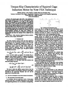
motors were designed in 3D as shown in Fig. 1. The skew angle of applied the permanent magnet is defined as shown in the Fig. 1.
(a) No-Skew
(b) Diagonal Skew
2. Model Analysis 2.1 PMSM Reference Machines In order to compare the impact of No-Skew, diagonal skew and V-Skew of permanent magnet on the rotor, PM *
Dept. of Electrical and Computer Engineering, Pusan National University, Korea. (
[email protected],
[email protected],
[email protected]) Received 13 August 2013, Accepted 21 October 2013
(c) V-Skew
Fig. 1. 3D Modeling and schematic of skew diagram
Jong Gun Lee, Ki Wook Lee, and Gwan Soo Park
2.2 Comparing the Overlapping Area of the Slot and Magnet Cogging torque is generated when reluctance of between the permanent magnet and the stator slot is different. Therefore, the overlapping area of the slot and magnet is related to cogging torque. So, Fig. 2 can be expressed to calculate the overlapping area of slot and the magnet when we are applying the general model and the skew model to predict the cogging torque. Fig. 3 appears a ratio of the area of between a one slot and the magnet. This graph shows that if the V-skew is applied, the shape of the air gap flux is similar to the sin function and the loss of flux is less than to apply the diagonal skew.
391
2.4 FEM 3D analysis In order to get a magnetic flux density, cogging torque and torque ripple by skew, 3D FEM analysis was conducted. And the FFT analysis and the Z-axis force are obtained through the result of the 3D FEM analysis.
(a) No Skew
(a) No Skew (b) Diagonal Skew (c) V-Skew Fig. 2. Schematic view of Slot and Magnet Diagram
(b) Diagonal skew (θ=6)
Fig. 3. Magnet area of one slot versus skew (c) V-Skew (θ=6)
2.3 Characteristic Analysis Cogging torque is that the magnetic energy of the motor moves to the minimum position, so it is caused by the interaction of the stator slot and rotor magnet regardless of the load current. The frequency component and the shape of cogging torque can be varied by adjusting the number of slots and the magnet. In general, equation (1) is expressed as cogging torque.
(1)
Wme = co-energy, we can see that the cogging torque is proportional to the change in flux linkage.
Fig. 4. Magnetic flux density Fig. 4 shows that magnetic flux density in the slots is changed by the skew of the magnet. Also magnetic flux in the slot can be seen evenly distributed. Fig. 5 (a) and (b) show that overlapping area of the slots and magnets is changed in the form, such as V-Skew by skew angle. Considering these changes, the overlapping area of the slots and magnets does not shrink when skew angle is increased because the form of distribution of air gap flux density is a V shape. In addition, the V-skew angle should not continue to grow because the overhang is caused by a large V-skew angle at the end of the motor.
392
Effects of V-Skew on the Torque Characteristic in Permanent Magnet Synchronous Motor
(a) No-Skew
Fig. 6 shows the distribution of the force for the NoSkew, diagonal skew and V-Skew the air gap. We can see the distribution of force in the air gap to change by the skew. So the result is predicted that changes in the value of the area of the graph can be used to predict the results.
(b) Diagonal Skew
(c) V-Skew (θ=6)
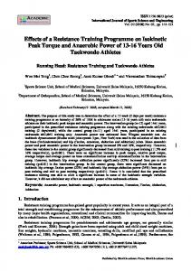
Fig. 5. Air Gap magnetic flux density Fig. 7. Cogging torque versus V-Skew angle Table1. Peak value of cogging torque versus V-Skew angle
(a) No-Skew
(b) Diagonal Skew (θ=6)
The cogging torque by according to change in V-skew angle is shown in Fig. 7. The Fig.7 is shown that the cogging torque is the minimum when the V-Skew angle is 6.
Fig. 8. Torque versus Skew angle
3. Conclusion
(c) V-skew (θ=6)
Fig. 6. Air gap force Distribution
In this paper, we study to find the optimal v-skew by comparing the change of the cogging torque. Fig. 7, 8 shows that the v-skew angle is 6 degree is the minimum cogging torque and torque ripple. Namely, the optimal VSkew is applied instead of one pitch of V-skew or diagonal skew. Through this, we are considering the optimal v-skew angle when we apply v-skew to a large permanent magnet motor. In the future, we research about the various impacts by v-skew on the motor.
Jong Gun Lee, Ki Wook Lee, and Gwan Soo Park
References [1] D.C. Hanselman, “Effect of skew, pole count and slot count on brushless motor radial force, cogging torque and back EMF”, IEEE Proceedings on Electric Power Applications, Vol.144, n5, pp. 325-330, Sep.1997 [2] Aimeng Wang, Heming Li, Weifu Lu, and Haisen Zhao, “Influence of Skewed and Segmented Magnet Rotor on IPM Machine Performance and Ripple Torque for Electric Traction,” IEEE Conference Publications, pp. 305-310, 2009 [3] T. Ishikawa, and G. Slemon “A Method of Reducing Ripple Torque in [4] Permanent Magnet Motors without Skewing,” IEEE Trans. Magnetics, Vol. 29, no. 2, pp. 2028-2031, 1993 [5] J.R.Hendershot, T.J.E.Miller,Design of Brushless PermanentMagnet Machines, 2nd ed., Magna Physics Publishing and Clarendon Press, pp. 107-108, 1994 [6] M. Aydin, “Magnet Skew in Cogging Torque Minimization of Axial Gap Permanent Magnet Motors”, Proceedings of International Conference on Electrical Machines, pp.1-6, 2008 [7] Rakib Islam, “ Permanent-Magnet Synchronous Motor Magnet Designs With Skewing for Torque Ripple and Cogging Torque Reduction”, IEEE Transactions on Industry Application , vol.45, no.1, pp. 152-160, 2009
Jong-Gun Lee received B.S degree in Electrical Engineering from Pusan National University, Busan, Korea. He entered the Collage of Electro-electrical engineering in Pusan National University, Busan, Korea, to study toward the Master degree. His research interests are designing Electric Machines and analyzing Finite Element Method.
Ki-Wook Lee received B.S degree in Electrical Engineering from Pusan National University, Busan, Korea. He entered the Collage of Electro-electrical engineering in Pusan National University, Busan, Korea, to study toward the Master degree. His research interests are designing Electric Machines and analyzing Finite Element Method.
393
Gwan-Soo Park received his B.S. degree from Seoul National University, Seoul, Korea in 1985, and his M.S. degree from Seoul National University of Electrical Engineering, Seoul, Korea in 1987, and his Ph.D. degree in Electrical Engineering from Seoul National University, Seoul, Korea in 1992. He is now working with Pusan National University and his research interests are Application of Electric Machines and Electromagnetic Devices.