B. Kosec, B. Karpe, A. Nagode, Faculty of Natural Sciences and Engi- neering, University of Ljubljana, .... tions of trial precursors. Temperature field in any solid ...
B. KOSEC, B. KARPE, I. BUDAK, M. LIČEN, M. ĐORĐEVIĆ, A. NAGODE, G. KOSEC
ISSN 0543-5846 METABK 51(1) 71-74 (2012) UDC – UDK 669.14.018.298:669.18=111
EFFICIENCY AND QUALITY OF INDUCTIVE HEATING AND QUENCHING OF PLANETARY SHAFTS Received – Prispjelo: 2010-06-22 Accepted – Prihvaćeno: 2011-03-03 Preliminary Note – Prethodno priopćenje
Presented work discusses a complex process of inductive heating and quenching of carbon steel planetary shafts for diesel engine starters. On the measurements base of temperature fields on the surface of the planetary shafts by thermographic camera and theoretical knowledge, a mathematical model for temperature conditions determination in the shaft during the entire process of heating and quenching was carried out. On the basis of developed mathematical model a computer program was developed, and used for analyses and induction hardening process optimization of planetary shafts. Key words: planetary shaft, inductive heating, quenching, mathematical model, quality Učinkovitost i kvaliteta indukcijskog zagrijavanja i kaljenja osovina startera dizel motora. U ovom se radu raspravlja o složenom procesu indukcijskog zagrijavanja i kaljenja osovina iz ugljičnog čelika za pokretanje dizelskih motora. Na temelju rezultata mjerenja temperaturnih polja na površini osovina termografskom kamerom i teorijskih spoznaja, razvijen je matematički model temperaturnih uvjeta tijekom procesa zagrijavanja i kaljenja osovina. Na temelju postavljenog matematičkog modela razvijen je računalni program koji je korišten za analizu i optimizaciju procesa zagrijavanja osovina. Ključne riječi: osovina, indukcijsko zagrijavanje, kaljenje, matematički model, kakvoća
INTRODUCTION Today the company Iskra Avtoelektrika d.d. from Šempeter near Gorica is one of the largest producers of electrical components and equipment for automotive, construction, agriculture mechanization and transport industry in European Union. Majority of these components are produced of carbon steel by different cold forming processes [1]. The most important of these components are surface fatigue strength under pulsating stress in combination with cyclic temperature loading and wear resistance. These properties can be achieved only by appropriate heat treatment [2-4]. For planetary shafts (∅14 × 155 mm) used for diesel engine starters (Figure 1) the most effective as well as the most common heat treatment is a combination of inductive heating and water quenching [5-9]. Long life span of carbon steel planetary shafts is essential for their economical production. Namely, replacement of starter is expensive from two points of view: money and working time [10,11]. Investigated planetary shaft is made of the well known Ck 45 carbon steel [12], which is one of the most applied materials for this kind of mechanical parts. B. Kosec, B. Karpe, A. Nagode, Faculty of Natural Sciences and Engineering, University of Ljubljana, Ljubljana, Slovenia. I. Budak, Faculty of Technical Sciences, University of Novi Sad, Novi Sad, Serbia. M. Ličen, Iskra Avtoelektrika, Gorica, Slovenia. M. Đorđević, TOC, Belgrade, Serbia. G. Kosec, Acroni d.o.o., Jesenice, Slovenia
METALURGIJA 51 (2012) 1, 71-74
Figure 1 Starter of a diesel engine with planetary shaft
INDUCTION SPIN-HARDENING In Iskra Avtoelektrika for induction spin-hardening thermal treatment of different mechanical parts and components the inductive spin-hardening device 3KTC (Figure 2) is used. This device was made by Italian company SAET from Turin. Device has been designed for spin case-hardening treatment of cylindrical shape products from 12 to 32 mm in diameter, and 100 to 500 mm length. The operating device and heat treatment parameters (used in the discussed case) were: theoretical power 93 kW, actual power 72,8 kW, frequency 83 kHz, voltage 508 V, heating time 2,5 s, quenching time 1,5 s, and total time of the cycle 15 s. 71
B. KOSEC et al.: EFFICIENCY AND QUALITY OF INDUCTIVE HEATING AND QUENCHING OF PLANETARY SHAFTS
Figure 2 Device 3KTC: inductor and manipulation system
TEMPERATURE MEASUREMENTS During induction heat treatment process the planetary shaft turns around its axis, which ensures uniform heating all over the surface and through the cross section (Figure 3). Temperature of the surface changes extremely rapidly from ambient temperature to approximately 1 120 °C. Rotational speed is approximately 10 rev/sec. Optimal heating time for required planetary shaft properties was found out to be 2,5 seconds, followed by 1,5 second quenching period with oil-water emulsion. After that, planetary shaft is ejected from manipulating system and cooled down in surrounding air. For planetary shaft surface temperature determination we used thermographic camera ThermaCAM PM675 FLIR System. Measurements were made in cooperation with company TERMING from Ljubljana. It is well known that emissivity is dependent upon material, surface quality and temperature [13,14]. According to literature data for Ck 45 steel [15], emissivity value varies in praxis between 0,6 and 0,9, depending
Figure 3 Induction heating of the planetary shaft
72
upon temperature and surface quality. In discussed case surface temperature varies between ambient temperature and approximately 1 120 °C. Furthermore, quality of surface changes from polished to heavily oxidized, which has significant influence on emissivity value. Because induction heating is a very fast process, we had to determine emissivity as engineering correct constant for the whole temperature range and surface mutation. For determination of real value of emissivity, we made comparative temperature measurements with Isotech T.T.I.7 thermograph and thermographic camera of the same planetary shaft, heated in electro-resistance furnace. Best fitting emissivity value for thermographic camera was in our case approximately 0,7. Several thermographic snapshots were recorded at regular intervals of induction heating (entire heating time is approximately 2,5 seconds). Thermograph record (Figure 4) is showing temperature profile on a surface of planetary shaft after approximately 2,5 second of induction heating (at the end of induction heating). Maximal measured temperature on bevel gear surface was 1 120 °C.
MATHEMATICAL MODEL Primary task of our work was to develop a mathematical model for thermal field calculation inside the planetary shaft during inductive heating and quenching, which would enable examination of temperature distribution at any time of induction heat treatment. Mathematical model is based upon different assumptions and boundary conditions. Planetary shaft is approximated as constant cross section cylinder. Material of the shaft is homogeneous and isotropic, thermal properties (thermal conductivity, specific heat) are temperature dependant, and density is assumed as a constant during entire induction spin casehardening process. Starting temperature field in the shaft is homogeneous and equal to the surrounding temperature. Surface temperature during induction heating is determined with thermographic camera measurements, during induction heating period, surface temperature rises between separate intervals monotonically to the measured temperatures for those particular intervals. Our mathematical model doesn’t consider released or consumed latent heat at the allotropic phase changes. Because of the ˝skin effect˝ phenomenon at the inductive heating, temperature at 0,2 mm below the surface has the same temperature as surface, and average heat transfer
Figure 4 Thermograph record at the end of induction heating process METALURGIJA 51 (2012) 1, 71-74
B. KOSEC et al.: EFFICIENCY AND QUALITY OF INDUCTIVE HEATING AND QUENCHING OF PLANETARY SHAFTS
coefficient in quenching period with oil-water emulsion is determined backwards, after microstructure observations of trial precursors. Temperature field in any solid body is monotonous function of time and space. For temperature distribution calculation inside planetary shaft we used cylindrical coordinate system. Because planetary shaft turns around its axis during entire induction spin case-hardening process, surface temperature is independent of the angle coordinate (φ), and we could make an assumption of two-dimensional (2D) transient heat transfer. Assuming 2D transient heat transfer with no internal heat generation or consumption and variable thermal properties, general Fourier’s partial differential equation reduces to the following form [16] : 1 ∂T ∂ ∂T ∂ ∂T ∂T ⋅(λ ⋅ ) + ⋅(λ ⋅ ) + ⋅(λ ⋅ ) = ρ ⋅c ⋅ r ∂r ∂r ∂r ∂z ∂z ∂t
where: r, z /m are coordinates of cylindrical coordinate system, T /K is temperature, ρ [kg/m3] is density, λ / W/(m⋅K) is thermal conductivity, and c /J/(kg⋅K) is specific heat. For calculation of temperature distribution inside planetary shaft we used explicit finite difference method (FDM), where thermal properties at given temperature are calculated for every time step with Lagrange interpolation [17].
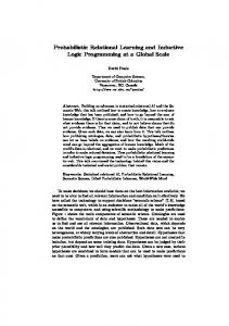
RESULTS AND DISCUSSION Numerical calculations results of temperature distribution through the cross-section 5 mm beneath upper groove (see Figure 6) for the case of induction heating (2,5 second) and quenching (1,5 second) with wateremulsion are shown in Figure 5. Average heat transfer coefficient in quenching period was determined on the basis of microstructure observation of trial precursors. Best fit value of heat transfer coefficient was 35 000 W/m2K. Figure 6 shows photograph of heat treated planetary shaft and its longitudinal cross-section (cutting was made with the water jet cutting machine) with clearly visible hardened case. Thickness of the hardened case is approx. 1,4 mm.
Figure 5 Calculated temperature field in planetary shaft during induction hardening process METALURGIJA 51 (2012) 1, 71-74
Figure 6 Heat treated planetary shaft - longitudinal crosssection
I II Figure 7 Steel microstructures at surface (I), and 2,1 mm depth under the surface (II)
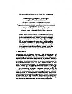
Microstructures of steel at different depths underneath the surface on cross section line are presented in Figure 7. Surface of the shaft is completely martensitic (I). However, at depth of 0,7 mm under the surface, the microstructure is composed of martensite and ferrite. The ferrite in the microstructure indicates that the transformation to austenite was not completed during induction heating period because the time for transformation was not long enough. Thickness of hardened case is approximately 1,4 mm, where constituents of microstructure are martensite, pearlite and ferrite. Beneath that depth microstructure is composed of pearlite and ferrite (II). In Figure 8 is shown graphical course of the HV5 hardness from the surface over the quenched layer to the core of the planetary shaft treated at standard conditions described in the chapter Induction spin-hardening.
CONCLUSIONS In the presented investigation induction spin-hardening process of carbon steel planetary shafts for diesel engine starters has been analyzed.
Figure 8 Hardness course measured over the hardened case of the planetary shaft
73
B. KOSEC et al.: EFFICIENCY AND QUALITY OF INDUCTIVE HEATING AND QUENCHING OF PLANETARY SHAFTS
Surface temperature thermographic camera measurements of planetary shaft during induction spin-heating period were carried out in industrial environment. On the basis of developed mathematical model we made a computer program for temperature distribution calculation inside planetary shaft. Boundary condition for numerical calculations was determined backwards, after microstructure observation of test precursors. On the basis of the numerical results we optimized heating and quenching time for induction hardening process of discussed planetary shaft.
REFERENCES [1]
B. Kosec, M. Brezigar, G. Kosec, J. Bernetič, M. Bizjak, Journal of Achievements in Materials and Manufacturing Engineering, 22 (2007) 2, 87 – 90. [2] L.A. Dobrzanski, Technical and Economical Issues of Materials Selection, Silesian Technical University, Gliwice, 1997. [3] G.E.Totten, M.A.H. Howes, Steel Heat Treatment, Marcel Dekker, New York, 1997. [4] M.L.C.F. Cannale, R.A. Mesquita, G.E. Totten, Failure Analysis of Heat Treated Steel Components, ASM International, Materials Park, Ohio, 2008. [5] G.E. Totten, M.A. Howes, I. Tatsuo, Handbook of Residual Stress and Deformation of Steel, ASM International, Materials Park, Ohio, 2002. [6] V. Rudnev, Handbook of Induction Heating, Marcel Dekker, New York – Basel, 2003. [7] M. Muhič, J. Tušek, F. Kosel, D. Klobčar, M. Pleterski, Metalurgija, 49 (2010) 1, 9 – 12.
74
[8] [9] [10] [11] [12] [13] [14] [15] [16] [17]
C.R. Brooks, Advanced Materials & Processes, 5 (2000) 12, 19 – 23. F. Cajner, B. Smoljan, D. Landek, Journal of Materials Processing Technology, 157-158 (2004), 55-60. W. Sitek, Journal of Achievements in Materials and Manufacturing Engineering, 39 (2010) 2, 115 – 160. B. Kosec, M. Karpe, M. Ličen, G. Kosec, Journal of Achievements in Materials and Manufacturing Engineering, 39 (2010) 2, 190 – 196. B. Jocić, Steels and Cast Irons, BIO-TOP, Dobja Vas, 2008. L. Machalski, K. Eckersdorf, K. McGhee, Temperature Measurement, John Wiley and Sons, Chichester, 1991. B. Kosec, G. Kosec, Metall, 57 (2003) 3, 134 – 136. P. Mullinger, B. Jenkins, Industrial and Process Furnaces – Principles, Design and Operation. Amsterdam: Butterworth – Heinemann, 2008. M. Kaviany, Principles of Heat Transfer, John Wiley & Sons, New York, 2002. R.W. Lewis, K. Morgan, H.R. Thomas, K.N. Seetharamu, The Finite Element Method in Heat Transfer Analysis, John Wiley & Sons, Chichester, 1996.
Note: This paper has been published under the title ‘’Inductive Heating and Quenching of Planetary Shafts‘’ in the journal ‘’Journal of Achievements in Materials and Manufacturing Engineering‘’, 39(2010)2, 190-196. On the request of the authors this paper is published as a rewrite short version. Also, has the permission of the Publisher: International OCSCO World Press. Note: The responsible translator for English language is Urška Letonja, University of Ljubljana, Slovenia
METALURGIJA 51 (2012) 1, 71-74