IEEE TRANSACTIONS ON AUDIO, SPEECH, AND LANGUAGE PROCESSING, VOL. 18, NO. 4, MAY 2010
773
Efficient Antialiasing Oscillator Algorithms Using Low-Order Fractional Delay Filters Juhan Nam, Student Member, IEEE, Vesa Välimäki, Senior Member, IEEE, Jonathan S. Abel, and Julius O. Smith
Abstract—One of the challenges in virtual analog synthesis is avoiding aliasing when generating classic waveforms such as sawtooth and square wave which have theoretically infinite bandwidth in their ideal forms. The human auditory system renders a certain amount of aliasing inaudible, which allows room for finding cost-effective algorithms. This paper suggests efficient algorithms to reduce the aliasing using low-order fractional delay filters in the framework of bandlimited impulse train (BLIT) synthesis. Examining Lagrange, B-spline interpolators and allpass fractional delay filters, optimized methods will be discussed for generating classic waveforms (sawtooth, square, and triangle). Techniques for generating more complicated harmonics such as pulse width modulation, hard-sync, and super-saw are also presented. The perceptual evaluation is performed by comparing the threshold of hearing and masking curve of oscillators with their aliasing levels. The result shows that the BLIT using the computationally efficient thirdorder B-spline generates waveforms that are perceptually free of aliasing within practically used fundamental frequencies. Index Terms—Antialiasing, audio oscillators, audio signal processing, interpolation, music, signal synthesis.
I. INTRODUCTION
T
HE fundamental idea of subtractive synthesis is to shape the spectrum by filtering a harmonically rich sound source. Many analog synthesizers of the 1960s and 1970s used a sound generation method based on subtractive synthesis. They consist of analog circuit modules including oscillators, filters, and amplifiers, connected internally or by patch cables such that rich harmonic sound generated by oscillators is processed by filters. Although the effort to implement signal representation of oscillators or filters in digital domain dates back to Music N in the 1950s and 1960s [1], it was in the 1990s that analog synthesizers were emulated as a complete unit of digital systems, beginning with the Nord Lead synthesizer introduced in 1995. Since then, “virtual analog synthesis” has become a popular term, referring to computational simulation of the sound generation principles of analog synthesizers [2].
Manuscript received March 31, 2009; revised September 15, 2009. Current version published April 14, 2010. The work of V. Välimäki was supported by the Academy of Finland under Project 126310. The associate editor coordinating the review of this manuscript and approving it for publication was Dr. Sylvain Marchand. J. Nam, J. S. Abel, and J. O. Smith are with the Center for Computer Research in Music and Acoustics (CCRMA), Stanford University, Stanford, CA 94305 USA (e-mail:
[email protected];
[email protected];
[email protected]). V. Välimäki is with the Department of Signal Processing and Acoustics, TKK-Helsinki University of Technology, FI-02015 TKK, Espoo, Finland, and also with the Center for Computer Research in Music and Acoustics (CCRMA), Stanford University, Stanford, CA 94305 USA (e-mail:
[email protected]). Digital Object Identifier 10.1109/TASL.2009.2035039
Oscillators of analog synthesizers typically include sawtooth, square, and triangular waveforms. Their rich spectra are realized by discontinuities in the waveform or its derivative, thereby having theoretically infinite bandwidth. In simulating analog signals in the digital domain, such wideband characteristics became a challenging issue because harmonic contents above the Nyquist limit are aliased, which causes unpleasant noise particularly at high fundamental frequencies. A number of methods have been proposed to remove or suppress the aliasing noise in digitally generated oscillators. An early method for synthesizing alias-free waveforms was by means of the so-called “discrete summation formulae,” which allows the generation of N harmonics of a fundamental simultaneously [3], [4]. This family of methods is essentially based on the closed-form expression of a geometric series , with set to a complex root of unity. This corresponds to harmonic additive synthesis to produce a bandlimited impulse train, but is more efficient computationally than producing each equal-amplitude harmonic sepa, with rately. A filter, such as a “leaky” integrator is required to integrate the bandlimited impulse train and approximate the classical square, triangle, and sawtooth waveforms and their spectra. Wavetable synthesis is an older, related approach that allows the production of perfectly bandlimited waveforms, but with limitations when the fundamental frequency must be varied over a wide range [5]. Another class of methods is called quasi-bandlimited techniques [6]. These methods do not eliminate aliasing completely, but rather suppress it just enough to make it less disturbing. An interpretation is that these methods sample low-pass-filtered continuous-time versions of classical waveforms. Stilson and Smith introduced the bandlimited impulse train (BLIT) method, in which an oversampled sinc-like pulse (a sampled, bandlimited impulse), is stored in a table during the design phase, and during synthesis, a train of bandlimited pulses is formed by periodically retrieving samples from that table, typically adding them when they overlap [7]. Filtering is again used to obtain bandlimited approximations of classical waveforms. Brandt developed the bandlimited step (BLEP) method, which is a variation of this idea: a correction function is added to the trivial classical waveforms to reduce aliasing [8]. The correction function is obtained as the difference of an approximately bandlimited step function and an ideal unit step function [6], [8]. In alias-suppressing methods, the spectral tilt of the input signal is modified to reduce aliasing [6]. A straightforward method is to oversample trivial waveforms and apply digital low-pass filtering before downsampling the signal [9]. This is inefficient for classical waveforms whose spectra decay slowly,
1558-7916/$26.00 © 2010 IEEE
774
IEEE TRANSACTIONS ON AUDIO, SPEECH, AND LANGUAGE PROCESSING, VOL. 18, NO. 4, MAY 2010
such as about 6 or 12 dB per octave. Lane et al. proposed a method that first distorts a sinusoidal signal and applies a shaping filter to approximate the desired waveshape and spectrum [10]. Välimäki used an integrated bipolar phase counter signal to produce a parabolic waveform [11]. It can be differentiated to obtain a sawtooth waveform, which suffers from less aliasing than the trivial sawtooth waveform. Recently, Pekonen and Välimäki have shown that it is possible to suppress aliasing with a postprocessing method, which utilizes a high-pass or a comb filter, or both [12]. Timoney et al. introduced a bandlimited impulse train generation algorithm and derived other classic waveforms using a modified FM synthesis [13]. The alias-free oscillator is ideally the most desirable case. Human hearing mechanisms, however, result in a certain level of aliasing being masked by neighboring harmonic peaks, which allows room for finding more cost-effective algorithms within the constraint of audio fidelity. In this paper, we introduce perceptually alias-free techniques within the range of practically used fundamental frequencies, using low-order fractional delay (FD) filters in the framework of the BLIT method. The FD filters examined include polynomial interpolators and allpass filters, aiming at using only simple arithmetic without lookup tables or numerically expensive functions. The quality and performance will be evaluated based on comparison of the aliasing and the masking curve from oscillators at high frequencies. The next section begins with generating bandlimited impulse trains. The impulse train is important in that it can be used as not only an oscillator type on its own but also as a basic building block to derive other types of oscillators by linear operations in the BLIT method [7]. In addition, the simple structure facilitates examining the operation of FD filters. II. GENERATING BANDLIMITED IMPULSE TRAINS
Fig. 1. (a) Diagram for generating a discrete-time bandlimited impulse train. (b) The trajectory of the phase counter. The circles indicate when the impulse response of an FIR FD filter is produced in the case that the length of the FD filter is four.
(3) is the sample index, is a sampled sequence of at and is the period of the bandlimited impulse train in samples. Since is not necessarily at each an integer multiple of , the sampled position of cannot be period generally varies. In other words, when is non-integer. In order computed from only for to be calculated in the discrete-time domain, we need to define another discrete-time impulse response which is obtained by shifting by the fractional time where
A. Discrete-Time Impulse Train by Fractional Delay Filters
(4)
An impulse train with period domain is represented as
in the continuous-time
(5)
(1)
and are the integer and fractional parts of where , respectively. From (4) is computed by sampling with the time offset of . Consequently, the disis expressed as crete-time bandlimited impulse train whose cosuccessive impulse responses of an FD filter efficients are updated every period. Fig. 1(a) shows a diagram . The phase to generate the bandlimited impulse train counter performs a special modulo “ ” operation which decrements phase in samples by one and, when it goes down below is added to it. Right before the phase counter wraps zero, around, it triggers an impulse to the fractional delay filter while of the phase counter determines the cothe fractional part efficients of FD filter . The trajectory of the phase counter is shown in Fig. 1(b) where the length of the FD filter is four. As such, a sequence of bandlimited impulses can be generated for a new fractional delay every period. Since the FD filter is obtained by sampling a continuous-time , aliasing contained in the discrete-time banlow-pass filter
In order to generate the discrete-time impulse train, the impulse must be bandlimited by a low-pass filter such that train harmonics above the Nyquist limit are rejected. The continuousmay be expressed as time bandlimited impulse train and a low-pass the convolution between the impulse train filter as (2)
where is the impulse response of the low-pass filter. Equation (2) can be interpreted as a periodic superposition of replica . By sampling it with sample period of impulse response , the discrete-time version of the bandlimited impulse train is obtained
NAM et al.: EFFICIENT ANTIALIASING OSCILLATOR ALGORITHMS USING LOW-ORDER FRACTIONAL DELAY FILTERS
775
As such, its inverse Fourier transform is given as a sinc function with a zero-crossing interval of one sample (9) This is known as the ideal bandlimited interpolator because it perfectly reconstructs a continuous-time signal from its sampled values, removing harmonics above the Nyquist limit. Therefore, the bandlimited impulse train using this FD filter does not cause aliasing at all as seen in Fig. 2(d). In general, the ideal bandlimited interpolator is not realizable with the signal flow graph in Fig. 1, because it is noncausal and infinitely long. However, it turns out that a periodically repeated sinc function can be represented in closed form because the impulse train convolved with the ideal bandlimited interpolator has a finite number of harmonic sinusoids in the frequency domain. This idea was generalized as a method called Discrete Summation Formulae (DSF) [4], which is applied to the BLIT as Fig. 2. Waveform and magnitude spectrum of bandlimited impulse trains using (a), (b) rounded-time unit impulses and (c), (d) the sampled sinc functions. The fundamental frequency is 2631 Hz (MIDI note #100) and the sampling rate is 44.1 kHz. Note that the spectral envelope of the rounded-time impulse train follows a sinc function.
dlimited impulse train is totally determined by the spectrum of the corresponding continuous-time low-pass filter. Accordingly, the aliasing reduction in the bandlimited impulse train ends up with designing a continuous-time low-pass filter, which finds an optimal solution in the trade-off between computational complexity and roll-off rate. In the next section, we will examine different types of continuous-time low-pass filters to obtain the FD filters. B. Rectangular Pulse and the Sinc Function The simplest FD filter is a rectangular pulse which is referred to as the zero-order hold otherwise.
(6)
By (6), we obtain a single unit-sample pulse every period at the nearest sample time to which the fractional delay is rounded, as shown in Fig. 2(a). The Fourier transform of the rectangular is given as a sinc function pulse (7) where
is the sampling rate (Hz) and is defined as . Although the computation is simple, the rectangular pulse as a low-pass filter causes significant aliasing as shown in Fig. 2(b) where the aliasing is enveloped by the sinc function in (7); specifically, the spectral envelope of the first generation of aliasing is obtained by wrapping the main lobe of the sinc function. Applying the duality between time and frequency domain to the rectangular pulse, an ideal low-pass filter can be obtained otherwise.
(8)
(10) where is the number of harmonics [3], [7]. While this method generates an alias-free impulse train in theory, it encounters a numerical problem in practice when the denominator is close to zero. In that case, the division of two sine functions is usually replaced with a constant in (10), which can generate a discontinuity when the numerical precision is limited. Another drawback of the DSF method is that it assumes that the waveform is invariably periodic so that an artifact may be generated by an instant change in frequency [14]. An alternative method is “Sum of Windowed Sincs (BLITSWS)” where the FD filter is given as a windowed sinc function. The window is chosen such that its spectrum has a steep roll-off, for example, Blackman or Kaiser window. BLIT-SWS is typically implemented using a lookup table with linear interpolation or polyphase lookup tables [6], [7]. As a result, the windowed sinc function with a limited resolution allows a certain amount of aliasing, which is determined by the window type, the number of zero-crossings and samples per zero-crossing. They are in fact involved with FIR filter design using windows. The BLIT-SWS method generates very effective quasi-bandlimited impulse trains with a large number of zero-crossings, such as, 16 or 32. However, it requires not only a large memory for the lookup table, but also the superposition of neighboring bandlimited impulses is likely to occur at high fundamental frequencies. For example, if the number of zero-crossings in a windowed sinc is 16, neighboring bandlimited impulses are superposed at . This requires addithe fundamental frequencies above tional computation as much as the number of superposed samples [14]. Therefore, the number of zero-crossings should be carefully chosen, trading off between the amount of aliasing and the efficiency. C. Polynomial Interpolators Polynomial interpolators are another group of FD filters. They have a similar feature to windowed-sinc functions in that the order of polynomials generally corresponds to the number
776
IEEE TRANSACTIONS ON AUDIO, SPEECH, AND LANGUAGE PROCESSING, VOL. 18, NO. 4, MAY 2010
of zero-crossings in the windowed sinc, both associated with the length of bandlimited pulses. Polynomial interpolators can be, however, computed at arbitrary times only with multiplication and addition without resorting to lookup tables. This is the primary advantage over windowed sinc functions, which have a limited resolution restricted by the size of the lookup table. At high orders, however, polynomial interpolators are usually impractical due to proportionally complicated coefficients. Therefore, we will focus on low-order polynomial interpolators up to order three. This also limits the width of bandlimited pulses up to four samples so that the overlapping between bandlimited pulses will not occur at the fundamental frequencies . There are a variety of known polynomial interpobelow lators [15], [16]. Lagrange interpolators and the B-spline are chosen here due to their distinct characteristics in the frequency domain and common use in signal processing. 1) Lagrange Interpolator: Lagrange interpolators can be seen as approximating the sinc function in a maximally flat manner at dc in the frequency domain [17]. This is a useful property for applications of modeling musical instruments, whose fundamental frequency is usually low. Meanwhile, Lagrange interpolator is known to be expressed as a windowed sinc function using a scaled binomial window [18], [19]. The Lagrange interpolators for order 1, 2, and 3 as continuous-time low-pass filters are defined as
(11) otherwise,
Fig. 3. Waveform and magnitude spectrum of bandlimited impulse trains using (a), (b) first-order (c), (d) second-order, and (e), (f) third-order Lagrange interpolators. The fundamental frequency is 2631 Hz (MIDI note #100) and the sampling rate is 44.1 kHz. The dashed lines are obtained by Fourier transforms of Lagrange interpolators.
(12) between positive and negative levels as in the sinc function. Fig. 3(b), (d), and (f) shows the corresponding spectra. The dashed lines indicate the envelopes of harmonic peaks and aliasing, which are determined by Fourier transforms of the Lagrange interpolators given by [22], [23]
otherwise,
(14) otherwise. (13) When the Lagrange interpolators in (11)–(13) are used as an FD filter, one instance per one polynomial segment is sampled depending on the fractional delay. For example, in the case of the third-order Lagrange interpolator, when the phase counter in Fig. 1 is between 2 and 2, each coefficient is obtained by of each polynomial segment. Then, the phase plugging it in for next period. Using a fast counter wraps around by adding algorithm, the th-order Lagrange FD filter coefficients can be multiplications and additions evaluated with about [19]–[21]. Therefore, the four coefficients can be computed only with ten multiplications and three additions. Fig. 3(a), (c), and (e) shows the bandlimited impulse trains generated using the Lagrange interpolators. Note that the bandlimited pulses in the second and third order fluctuate
(15) (16) and contain the quadratic terms In (15) and (16), as a function of frequency. They work as tilting the spectrum upward with regard to dc, indicating that they are related to the maximal flatness of Lagrange interpolator at dc. As a result, harmonic peaks in the high frequency range are less attenuated, whereas the alias reduction by the power of sinc function is canceled out as much. 2) B-Spline Interpolator: B-splines interpolators are bellshaped polynomial interpolators constructed by iterative convolution of a rectangular pulse [24]. Therefore, the first-order B-spline interpolator is obtained by convolving the rectangular
NAM et al.: EFFICIENT ANTIALIASING OSCILLATOR ALGORITHMS USING LOW-ORDER FRACTIONAL DELAY FILTERS
777
pulse in (6) with itself, which is the same as the first-order Lain (11). The second and third-order grange interpolator, polynomials are also obtained by successive convolution with the rectangular pulse
(17) otherwise
(18)
otherwise. Fig. 4(a) and (c) shows the bandlimited impulse trains using the second and third B-spline interpolators. As in the Lagrange interpolators, pulse instances are sampled from each polynomial segment in (17) and (18) every period, according to the phase counter. By the convolution theorem, the Fourier transforms of the B-spline interpolators are simply given as the power of sinc function (19) (20) As seen in Fig. 4(b) and (d), the aliasing is significantly reduced compared to the Lagrange interpolators for the same order. This is also apparent from comparison of the Fourier transforms in (15) and (16) to (19) and (20) where the B-spline interpolators consist of only the power of sinc function whereas the Lagrange interpolators contain the additional spectral tilting factors, which boost the level of aliasing. Though harmonic peaks in the high-frequency range are attenuated more in the spectrum of the B-spline interpolators, the level is only 3 dB at 10 kHz and 6.9 dB at 15 kHz with the 44.1 kHz sampling rate, and if necessary, can be equalized by a one-pole one-zero filter. In general, when the derivative of a polynomial is continuous, the polynomial has approximately 6 dB per octave decay relatively to its derivative in spectrum. The th-order B-spline polynomial has a property that its derivatives up to the th-order are continuous so that they have dB per octave roll-off in spectrum. On the other hand, the Lagrange interpolator has a discontinuity in the polynomial functions or its derivatives, which is seen to slow down the roll-off rate. This is the underlying principle that the B-spline interpolators are more effective in reducing the aliasing. D. Allpass Fractional Delay Filters The FD filters discussed above are represented as an FIR filter whose impulse response is given as sampled instances of continuous-time low-pass filters. On the other hand, allpass FD filters are in a different category in that they are IIR filters and
Fig. 4. Waveform and magnitude spectrum of bandlimited impulse trains using (a), (b) second-order and (c), (d) third-order B-spline interpolators. The fundamental frequency is 2631 Hz (MIDI note #100) and the sampling rate is 44.1 kHz. The dashed lines are obtained by Fourier transforms of B-spline interpolators.
have no explicit connection to their continuous-time versions. The details of allpass FD filters are examined in [19]. Here, the first- and second-order Thiran allpass filters are chosen to generate the bandlimited impulse train. The Thiran allpass filter is a family of allpass filters that has a maximally flat group delay at dc. The property is well suited to musical applications like Lagrange interpolator [19]. The first-order allpass filter is computed by the following recursive equation: (21) where the coefficient
is computed by setting its dc delay to
(22) The delay is chosen to be between 0.418 and 1.418, which is the optimal range for the first-order allpass filter to have maximally flat delay over all frequency range [19]. This is also related to the effective length of the first-order allpass filter, which is defined as the smallest nonnegative integer time index by which 99% of the total energy is accumulated [26]. For the chosen delay , the fractional delay is between 0.582 and 0.418 , which corresponds to the effective length within three samples in Fig. 5. This indicates that the first-order allpass filter can be approximated to an FIR filter with the length of four samples at most. When the allpass filter is used to generate a bandlimited impulse train, the input is given as a single impulse. Therefore, (21), instead of using the two multiplications and two additions
778
IEEE TRANSACTIONS ON AUDIO, SPEECH, AND LANGUAGE PROCESSING, VOL. 18, NO. 4, MAY 2010
Fig. 5. Effective length of the first- and second-order Thiran allpass filters for 99% energy accumulation.
per sample, can be decomposed into more efficient segments by calculating the first two outputs individually in (21)
(23) otherwise. That is, when the phase counter is between 0.418 and 1.418, the first sample is computed by plugging it in of (22) and the second sample by using the result of the first sample. Then, as , the following the phase counter wraps around by adding samples are recursively computed from the previous output by . Note that, in comparison to polynomial multiplying with interpolators, once the coefficient is computed in the first segment, it is repeatedly used during a period. Fig. 6(a) shows that the bandlimited impulse train using the first-order allpass filter. As explained, the bandlimited impulse is similar to the result using an FIR filter with the length of four samples. Fig. 6(b) shows the magnitude spectrum of the bandlimited impulse train using the first-order Thiran allpass filter. It is seen to have considerable aliasing but there is a decent suppression below the fundamental frequency, which is generally the most audible region. The aliasing level in the region is seen to be lower than using the linear interpolator and close to using the second-order Lagrange interpolator. A drawback of the Thiran allpass filter is that a division is necessary in (22) every period. It can be replaced with multiplications by using the following approximation: (24) where
Since is much less than one and , (24) converges factors in (24) have a form of fast. For example, the first three factors amounts to about 99% and the first four factors to 99.9% of the coefficient.
Fig. 6. Waveform and magnitude spectrum of bandlimited impulse trains using (a), (b) the first-order and (c), (d) the second-order allpass filter. The fundamental frequency is 2631 Hz (MIDI note #100) and the sampling rate is 44.1 kHz.
The second-order Thiran allpass filter is given as the following recursive equation: (25) and the coefficients are computed with regard to the delay [25] (26) The delay is chosen to be kept between 1.5 and 2.5. The frac. tional delay for the range is between 0.5 and 0.5 It corresponds to the effective length within 4 in Fig. 5, indicating that the second-order allpass filter can be approximated to an FIR filter with the length of 5 samples at most. As in the first-order allpass filter, (25) can be decomposed into an efficient form of segments
(27) otherwise. When the phase counter is between 1.5 and 2.5, the first sample is triggered by plugging it in (26). Once and are computed, they can be reused in next samples during a period. Fig. 6(c) shows the bandlimited impulse train using the second-order allpass filter, which is approximately one sample longer than using the first-order allpass filter. In the spectrum in Fig. 6(d), the aliasing is significantly reduced around the fundamental frequency. The result is seen to be close to that of using the thirdorder Lagrange interpolator. It is surprising that the harmonic peaks are slightly attenuated also when first- and second-order allpass filters are used, see Fig. 6(b) and 6(d). The attenuation at the Nyquist limit is in both cases about 3.9 dB, which is less than for Lagrange or B-spline interpolators, cf. Fig. 3 and Fig. 4.
NAM et al.: EFFICIENT ANTIALIASING OSCILLATOR ALGORITHMS USING LOW-ORDER FRACTIONAL DELAY FILTERS
The divisions in (26) also can be avoided by using the following approximations:
(28)
(29) where
Since is between 0.125 and 0.375 and is between 0.125 and 0.125, (28) and (29) converge fast as well, so that the coefficients can be well approximated by the first three or four factors.
779
and yet, increasing the leak rate can make the waveform sound brighter and out of shape. Consequently, varying the leak rate depending on the fundamental frequency will be appropriate, especially for high fundamental frequencies where the aliasing is the main concern and the number of harmonics is small. Another method is to use a highpass filter such as a dc blocker. Actually, the dc blocker can be used to reduce the aliasing below the fundamental frequency [12]. However, it requires a trade-off between the low-harmonic attenuation and the sharp notch at dc which increases the transient behaviors [27]. The second problem with the small leak rate is associated with the dc offset. Since the bandlimited impulse trains examined above are expressed as a series of impulse responses of low-pass or allpass filters, they preserve a dc component by its nature. Therefore, integrating the bandlimited impulse trains with the small leak rate can cause the waveform to drift upward and possibly generate an audible artifact by clipping limit. The dc offset is determined by the average value over a period of bandlimited impulse trains. In the steady state, therefore, the dc offset remains at a constant level, which can be removed by subtracting the precomputed dc level. For example, the dc offset of Lagrange and B-spline interpolators is explicitly given as
III. GENERATING BANDLIMITED CLASSIC WAVEFORMS The principle of the BLIT method is that classic waveforms such as sawtooth, square, and triangular can be derived from a bandlimited impulse train via linear operations which do not introduce new harmonics; therefore, they also remain bandlimited [7]. We begin with discussing the linear operations, then proceed to generating a variety of waveforms found in analog synthesizers. All waveforms presented here will be based on the bandlimited impulse trains using the third-order B-spline interpolator because it produced the best result in reducing the aliasing. A. Leaky Integrator and DC Offset Sawtooth, square and triangular waveforms have a 6 dB or 12 dB per octave roll-off in spectrum. The spectral roll-offs or , which correspond to the functions of frequency, can be analytically performed by single or double integrations. In the BLIT method, the integration is performed by a leaky integrator given as a simple one-pole filter
where the leak rate is greater than zero so as to avoid overflow by numerical errors, such as from quantization. In general, it is desirable to set the leak rate to a small value ) such that the spectral envelope rolls off from (e.g., low frequencies and the shape of the waveform is close to the original. However, the small leak rate can be problematic in two aspects. First, the aliasing below the fundamental frequency can be boosted by the leaky integrator. For example, if an aliasing component is located one octave below the fundamental frequency, the level of the aliasing component will increase by 6 dB by the leaky integrator. One way of preventing it is to increase the leak rate in high fundamental frequencies so that the spectral envelope starts to roll off near the fundamental frequency,
(30) is the period of the bandlimited impulse train in samwhere ples, because their sum of coefficients is equal to one. The dc offset of the allpass FD filters is also approximated to (30) as long as the fundamental frequency is not so high that the sum of coefficients converges to one within a period. On the other hand, in the non-steady state, for example, when the fundamental frequency or other parameters changes on the fly, the transient dc offset cannot be removed only with the precomputed dc offset. Even the dc blocker is not effective to avoid it because it is not free of the transient dc offset, either, especially when its pole is located near the unit circle. A method to fix the problem is to update parameters every period such that the waveform is held in a steady-state during each period. Then, the dc level will remain constant during each period and can be removed by subtracting the precomputed dc offset. The phase counter in Fig. 1 actually implements the idea by wrapevery period. Though ping around with a new sample period the period-based update limits a modulation resolution to the sample period so that an artifact can be generated in audio-rate modulations with a large depth, it generally works well for most modulations such as by low frequency oscillator (LFO) or envelope control. Another source of the transient dc offset is the initial state of the waveforms. It can be fixed up by setting appropriate initial conditions to the phase counter and the leaky integrator. More details will be explained in each waveform generation below. B. Sawtooth Waveform The sawtooth waveform has harmonics at all integer multiples of the fundamental frequency with a 6 dB per octave roll-off. Therefore, it can be generated by subtracting the dc offset from the BLIT and integrating it as in Fig. 7(a)
780
IEEE TRANSACTIONS ON AUDIO, SPEECH, AND LANGUAGE PROCESSING, VOL. 18, NO. 4, MAY 2010
Fig. 7. Diagrams for generating BLIT-based oscillators: (a) sawtooth, (b) square, and (c) triangular waveforms.
[7]. Fig. 8(a) shows a sawtooth waveform derived from the BLIT using the third-order B-spline interpolator. It appears as a falling waveform due to the subtraction of the dc offset. Its amplitude ranges approximately from 0.5 to 0.5 because the sum of the bandlimited impulses is about one, which becomes the peak-to-peak level. In order to avoid the initial drifting by the transient dc offset, the initial condition of the phase counter in Fig. 1 must be synced to the initial condition of the leaky integrator. The relation is given as . In Fig. 8(a), the initial conditions were set to and 0, respectively by the relation such that the waveform starts from zero. Fig. 8(b) shows the magnitude spectrum of the sawtooth waveform. It is similar to the spectrum of the BLIT in Fig. 4(d) except that the aliasing at high frequencies is moderately suppressed by the leaky integrator. The deviation from the dashed line ( 6 dB per octave slope) is caused by the low-pass filtering of the third-order B-spline interpolator. As discussed before, it is not significantly audible and, if necessary, can be compensated by a one-pole one-zero filter. C. Bipolar BLIT and Square Waveform The square waveform has harmonics at odd multiples of the fundamental frequency with a 6 dB per octave roll-off. The odd harmonics can be generated by a bipolar BLIT whose pulses alternate sign. Since the dc offset is canceled out by the bipolar BLIT, the square waveform can be generated by only integrating the bipolar BLIT as shown in Fig. 7(b) [7]. There are several known methods to generate the bipolar BLIT using a BLIT. The simplest method is to alternate the sign of the impulse and set operation [7]. Other methods the phase counter to modulo include using a difference of two BLITs and a combination of a BLIT with an FIR comb filter [2], [7]. Fig. 8(c) shows a square waveform derived by integrating the bipolar BLIT using the third-order B-spline interpolator. In order to avoid the initial drifting in the square waveform, the initial condition of the leaky integrator must be set to either the minimum or maximum level, which is 0.5 or 0.5 in this case. The choice is determined by the sign of the impulse in the BLIT. That is, if the
Fig. 8. Waveform and magnitude spectrum of (a), (b) sawtooth (c), (d) square, and (e), (f) triangular signals. They are derived from the BLIT using the thirdorder B-spline interpolator. The fundamental frequency is 2631 Hz (MIDI note #100) and the sampling rate is 44.1 kHz. The dashed lines are the roll-off slope of (b), (d) 6 dB per octave and (f) 12 dB per octave. The leak rate is set to 0.01.
0
0
impulse starts with positive sign, the initial value of the leaky integrator must be set to 0.5 such that the waveform jumps to 0.5 by the integration of the B-spline coefficients, and vice versa. Though the initial condition of the phase counter does not influence the initial drifting, the complete shape of the first period . Fig. 8(d) shows the magcan be obtained by setting it to nitude spectrum of the square waveform, which contains only odd harmonics and sparser aliasing as much. D. Triangular Waveform The triangular waveform has harmonics at odd multiples of the fundamental frequency with a 12 dB per octave roll-off. Therefore, it can be generated by integrating the bipolar BLIT twice as shown in Fig. 7(c) [7]. Due to the successive integration, it requires more restricted conditions to avoid the initial drifting. Since the triangular wave is obtained by integrating the square wave as well, the initial conditions for the square wave above are required. On top of that, the initial condition of the and the iniphase counter must be set to a quarter period tial condition of the second integrator to zero. These conditions enable the triangular waveform to start from zero and change its slope after a quarter period without the initial drifting as shown in Fig. 8(e). While the amplitudes of the sawtooth and square
NAM et al.: EFFICIENT ANTIALIASING OSCILLATOR ALGORITHMS USING LOW-ORDER FRACTIONAL DELAY FILTERS
781
Fig. 9. Diagrams for generating BLIT-based oscillators: (a) PWM, (b) hardsync, and (c) super-saw.
waveforms are determined by the integration of the FD filter coefficients ranging between 0.5 and 0.5, a triangular waveform needs fix-up for the amplitude scaling by the second integration. The scaling factor is derived by setting the integration over a quarter period of a square waveform equal to the peak value . This results in the scaling of a triangular waveform , which is represented as multiplication by in factor of Fig. 7(c). Fig. 8(e) and (f) shows the triangular waveform and its spectrum derived from the bipolar BLIT. It is seen that the aliasing is reduced more by the second integration, compared to the square waveform. E. PWM Pulse width modulation (PWM) is a modulation technique to create a rich spectrum by modulating the width of a square waveform. It requires a square waveform with a variable dutycycle, which can be generated by integrating a difference of two BLITs as shown in Fig. 9(a) [7]. The pulse width can be controlled by synchronizing the phase counter of BLIT with negative sign to the phase counter of BLIT with positive sign. The where is phase difference is set to is a period in samples. Fig. 10(a) shows the duty-cycle and a PWM waveform derived from the bipolar BLIT using the third-order B-spline where the duty-cycle is set to 30%. Note that the waveform is shifted up by 0.2. It is caused by the dc cancellation in the bipolar BLIT such that the integration over a period is zero. Though it makes the waveform drift up or down by a time-varying modulation, the level of drifting is limited
Fig. 10. Waveform and magnitude spectrum of (a), (b) PWM (c), (d) Hard-sync sawtooth waveform, and (e), (f) super-saw. They are derived from the bandlimited impulse train using the third-order B-spline. The fundamental frequency is 2631 Hz (MIDI note #100) and the sampling rate is 44.1 kHz. In the hard-sync sawtooth waveform, the fundamental frequency of the slave oscillator is 3800 Hz.
to the range between 0.5 and 0.5. Fig. 10(b) shows the spectrum of the PWM waveform. The spectral envelope is seen to be irregular and even harmonics are also generated due to the asymmetry of the waveform between the positive and negative shapes. F. Hard-Sync Hard-Sync is another modulation technique to produce a wide variety of timbres by synchronizing two oscillators, a master and a slave. The oscillator synchronization is performed by resetting the phase of the slave oscillator every time the master oscillator cycles around [8]. The slave oscillator usually has a higher fundamental frequency than the master’s, which associates the master with the pitch and the slave with the shape of the waveform. Brandt introduced a method to generate a hard-sync sawtooth waveform using the BLIT (and also BLEP) [8]. The BLIT-based hard-sync waveform is represented by the sum of the master and slave BLIT as in Fig. 9(b). The scaling factor for the master BLIT is determined by the fractional part where and are the period of the master and of slave, respectively. In the BLIT generation scheme here, the synchronization is carried out by replacing the phase counter of the slave BLIT with that of the master BLIT whenever the master wraps around. Fig. 10(c) shows the hard-sync waveform
782
IEEE TRANSACTIONS ON AUDIO, SPEECH, AND LANGUAGE PROCESSING, VOL. 18, NO. 4, MAY 2010
using the master and slave BLIT. The synchronization occurs about every 16.8 sample, corresponding to the sample period of the master BLIT. The spectrum is presented in Fig. 10(d). Interesting sounds are obtained from time-varying spectrum, which is controlled by the fundamental frequency of the slave oscillator. G. Super-Saw Super-Saw is a special waveform to generate thick stringtype sounds, originally created by Roland in their JP-8000 and JP-8080 analog modeling synthesizers [28]. The rich sound is achieved by the chorus effect among slightly detuned sawtooth waveforms. In the BLIT method, it can be emulated by inteBLITs (typically, ) as shown in grating the sum of Fig. 9(c). Fig. 10(e) and (f) shows the waveform and its spectrum. The 6 BLITs were detuned by 7, 14, 21 cents flat and 4, 8, 12 centers sharp with regard to the fundamental frequency [29].
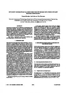
Fig. 11. Examples of spectra and masking curves of the bandlimited impulse train using the third-order B-spline interpolator. The fundamental frequencies are (a) 2631 Hz and (b) 6700 Hz, and the sampling rate is 44.1 kHz. The aliased component that exceeds the masking threshold is marked with a circle.
a spreading function for a masker. We use the following asymmetric spreading function:
IV. EVALUATION AND COMPARISON A. Perceptual Evaluation
(32)
The bandlimited oscillators using low-order FD filters contain aliasing as shown in the previous spectra. The human auditory system can render the aliasing inaudible in certain conditions [30]. The main psychoacoustic phenomenon involved is masking [30]. That is, if an aliased component is located near a harmonic peak and its level is below a certain level, it is masked by the sensory system so that the aliasing is not perceived. Another aspect is the hearing threshold in quiet. Especially, the hearing threshold level dramatically increases above 15 kHz [30]. The aliasing in the bandlimited oscillators generally becomes more audible for higher fundamental frequencies because the level of the aliasing relatively increases. Therefore, the sound quality of the bandlimited oscillators can be evaluated by identifying the maximum fundamental frequency up to which the aliasing is not audible. The most straightforward method to find it is listening to the oscillators in person, for example, by sweeping the fundamental frequency or comparing it to an alias-free reference sound. However, such methods are somewhat arbitrary depending on subjects or audio systems and settings to play the oscillators. Therefore, an objective approach based on psychoacoustic models is necessary. Here we propose a method of evaluating the bandlimited oscillators by comparing their masking curves with the levels of aliased components. This is based on computational models of hearing threshold and masking approximated from experimental data [30]. The hearing threshold curve used for this method is given by [31]
(31) where is frequency in Hz and the level is represented as absolute sound pressure level (SPL). The masking is modeled as
is a difference between the frequency of a masker where is the level of masker and a maskee in Bark units, and is the step function equal to zero for in dB SPL and and one for [32]. Note that the peaks of the spreading functions are equal to the level of maskers. They are actually shifted down by a certain level, which is typically greater for a tonal masker than a noise-like masker. For the bandlimited oscillators that contain nearly tonal maskers, the downshift level is set to 10 dB [33]. The masking curve is computed by taking the maximum level among spreading functions of harmonic peaks and the hearing threshold curve. To accommodate harmonic peaks in the spreading function, the spectral power of the oscillators should be scaled to dB SPL. The reference used was set to 96 dB SPL for a sinusoid alternating between 1 and 1, assuming that they are played at a sufficiently loud level. Fig. 11 illustrates the computed masking curves of a bandlimited impulse train for two fundamental frequencies. At 2631 Hz, the aliased components are fairly abundant in high frequencies but they are completely masked by harmonic peaks and the hearing threshold, as seen in Fig. 11(a), implying that the oscillator is perceptually free of disturbances. On the other hand, at 6700 Hz, a single aliased component above the masking curve is found, see Fig. 11(b), indicating that the tone contains audible noise. By comparing the masking curve with the levels of aliased components this way, the highest fundamental frequency up to which the aliasing is not perceived can be found as a measure of evaluating the bandlimited oscillators. Table I presents the result for the examined bandlimited impulse trains. As shown in the spectra, the B-spline interpolators had higher fundamental frequencies than the others for the same order in general. The aliased component exceeding the masking curve was mainly found below the fundamental in the B-spline and Lagrange interpolators, whereas it was around higher overtones in the Thiran allpass filters. It is because the aliased components in the allpass filters are distributed more toward higher
NAM et al.: EFFICIENT ANTIALIASING OSCILLATOR ALGORITHMS USING LOW-ORDER FRACTIONAL DELAY FILTERS
783
TABLE I HIGHEST FUNDAMENTAL FREQUENCY THAT IS PERCEPTUALLY FREE OF ALIASING FOR THE BANDLIMITED IMPULSE TRAINS
TABLE II HIGHEST FUNDAMENTAL FREQUENCY THAT IS PERCEPTUALLY FREE OF ALIASING FOR SAWTOOTH GENERATION ALGORITHMS. BOTH BLIT-SWS AND BLEP USED BLACKMAN WINDOW WITH 64 TIMES OVERSAMPLING AND EIGHT ZERO-CROSSINGS. BLIT-FDF USED THE THIRD-ORDER B-SPLINE
frequencies as shown in Fig. 6(b) and (d). When only the frequency range below the fundamental, which is the most dominant disturbance, was compared, the highest fundamental frequencies for the first and second-order allpass filters increased to 2239 and 4220 Hz, respectively.
and BLEP require a wavetable for a windowed-sinc or a modified form, whose size determines the sound quality. In terms of computational complexity, DPW and DPW-2X are seen to be simpler than others, because they require only up to several multiplications and additions per sample [11]. The BLIT-FDF, BLIT-SWS and BLEP methods have an irregular number of computations in common, because they compute bandlimiting samples only at transition regions where the sawtooth waveform wraps around, and otherwise produce zeros or a trivial sawtooth waveform. To compute a bandlimiting sample, the BLIT-FDF method using the third-order B-spline interpolator requires up to three multiplications and two additions as seen in (18), whereas the BLIT-SWS and BLEP methods read a lookup table using linear interpolation, which typically involves several multiplications and additions as well as accessing memory twice. The number of bandlimiting samples is proportional to the order of FD filters or the number of zero-crossings in BLIT-SWS and BLEP (four and eight samples in the compared algorithms, respectively). Though these algorithms require conditional logic to identify transition regions and accordingly more lines of instructions, the average number of computations per sample is quite small, especially at low fundamental frequencies. For example, when the period is 100 samples (441 Hz at a sampling rate 44.1 kHz), the BLIT-FDF method computes only four samples every period and produces zeros during the rest of sample times before the dc removal and integration. In summary, this result shows that the compared algorithms have both advantages and disadvantages in terms of the sound quality and efficiency, so that a trade-off is necessary. Among them, the proposed BLIT-FDF method is seen to be an optimized solution in the sense that aliasing is effectively reduced with relatively less computations and no lookup table.
B. Comparison With Other Algorithms to Generate Sawtooth Waveforms Several quasi-bandlimited and alias-suppressing methods to generate classic waveforms were reviewed in the beginning of this paper. We compare the Lane, DPW, BLIT-SWS, and BLEP methods to the BLIT method using the FD filters (BLIT-FDF) in terms of the perceptual evaluation performed above and efficiency in implementation. Among the examined FD filters, the third-order B-spline interpolator was selected due to its superiority in aliasing reduction. In the BLIT-SWS and BLEP methods, an FIR filter was designed using the Blackman window with 64 times oversampling and eight zero-crossings, and linear interpolation was used for the table lookup. Table II shows the highest fundamental frequency that is perceptually alias-free for compared sawtooth generation algorithms. The alias-suppressing methods such as Lane and DPW had aliased components exceeding the masking curve at relatively low fundamental frequencies. The oversampled version of the DPW made a decent improvement. In the quasi-bandlimited methods, the BLIT-SWS method turned out to have the audible aliasing at a quite low fundamental frequency, whereas the BLEP method using the same window resulted in a significantly higher fundamental frequency. Both BLIT-FDF and BLEP methods covered fundamental frequencies above the highest tone of the piano, a C8 (4186 Hz), indicating that they are perceptually free of aliasing within the practically used frequency range. Note that there is a difference in the highest fundamental frequency between the impulse train and sawtooth waveform using the third-order B-spline interpolator in Tables I and II. It is because the sawtooth waveform was scaled to be kept between 1 to 1 after going through the leaky integrator, which boosted the aliasing level. Efficiency of those algorithms heavily depends on systems in which they are implemented. In terms of memory consumption, the DPW, DPW-2X and BLIT-FDF methods have an advantage because they use only simple arithmetic without any lookup tables. Lane’s method requires more computations, because it uses a sine oscillator [10]. On the other hand, the BLIT-SWS
V. CONCLUSION It was shown that bandlimited impulse trains can be produced as a sequence of a fractional delay filter’s impulse responses. The fractional delay parameter is changed for every pulse, but remains constant for the duration of each impulse response. This new approach avoids the use of a lookup table and oversampling of the prototype pulse, which are needed in previous BLIT implementations. In the proposed method, the fractional delay parameter does not have to be quantized more coarsely than dictated by the numerical accuracy.
784
IEEE TRANSACTIONS ON AUDIO, SPEECH, AND LANGUAGE PROCESSING, VOL. 18, NO. 4, MAY 2010
Three classes of FD filters, the Lagrange interpolation, the B-spline, and the Thiran allpass filters were considered in this paper. All classical synthesizer waveforms, such as the sawtooth, square, and triangular signal, are obtained by leaky integration of a uni- or bipolar pulse train generated using one of these FD filters. An appropriate dc level must be subtracted prior to integration. Furthermore, efficient new implementations for the pulse-width modulation, hard-sync effects, and the super-saw oscillator were introduced. The sound quality obtained with the different filters was evaluated by applying a masking curve model to each desired signal partial. Additionally, a frequency-dependent hearing threshold curve was applied to indicate that spectral components above 15 kHz or so are inaudible in the waveforms of interest. This way it was possible to show as a function of the fundamental frequency whether aliasing is audible or not for tones produced with different FD filters. The fundamental frequency range where aliasing is inaudible was reported for BLIT synthesis using all three FD filters. The same evaluation was repeated for bandlimited sawtooth waveforms generated with several previous techniques and the best proposed method. It was found that low-order FD filters can yield excellent antialiasing oscillators. For the proposed fractional delay BLIT synthesis, the third-order B-spline filter is the best among the candidate FD filters. It can produce perceptually alias-free waveforms up to the fundamental frequency of 5.8 kHz, which is higher than the topmost tone in the piano. When a lower sound quality can be tolerated or a smaller computational load is required, the second-order B-spline or the second-order Thiran allpass filter is recommended. Lagrange FD filters cannot compete with these techniques, when alias suppression and computational complexity are considered. ACKNOWLEDGMENT The first author would like to thank Dr. T. Stilson for helpful discussions on this topic and Prof. M. Bosi for advice on auditory masking. The authors would like to thank A. Franck for providing references to closed-form expressions of Fourier transforms of Lagrange interpolators. REFERENCES [1] M. V. Mathews, The Technology of Computer Music. Cambridge, MA: MIT Press, 1969. [2] V. Välimäki and A. Huovilainen, “Oscillator and filter algorithms for virtual analog synthesis,” Comput. Music J., vol. 30, no. 2, pp. 19–31, Summer, 2006. [3] G. Winham and K. Steiglitz, “Input generators for digital sound synthesis,” J. Acoust. Soc. Amer., vol. 47, pt. 2, pp. 665–666, Feb. 1970. [4] J. A. Moorer, “The synthesis of complex audio spectra by means of discrete summation formulae,” J. Audio Eng. Soc., vol. 24, pp. 717–727, Dec. 1975. [5] D. C. Massie, “Wavetable sampling synthesis,” in Applications of Digital Signal Processing to Audio and Acoustics, M. Kahrs and K. Brandenburg, Eds. Norwell, MA: Kluwer, 1998, pp. 311–341. [6] V. Välimäki and A. Huovilainen, “Antialiasing oscillators in subtractive synthesis,” IEEE Signal Process. Mag., vol. 24, no. 2, pp. 116–125, Mar. 2007. [7] T. Stilson and J. Smith, “Alias-free digital synthesis of classic analog waveforms,” in Proc. Int. Comput. Music Conf., Hong Kong, China, 1996, pp. 332–335. [8] E. Brandt, “Hard sync without aliasing,” in Proc. Int. Comput. Music Conf., Havana, Cuba, 2001, pp. 365–368.
[9] H. Chamberlin, Musical Applications of Microprocessors, 2nd ed. New York: Hayden, 1985. [10] J. Lane, D. Hoory, E. Martinez, and P. Wang, “Modeling analog synthesis with DSPs,” Comput. Music J., vol. 21, no. 4, pp. 23–41, 1997. [11] V. Välimäki, “Discrete-time synthesis of the sawtooth waveform with reduced aliasing,” IEEE Signal Process. Lett., vol. 12, no. 3, pp. 214–217, Mar. 2005. [12] J. Pekonen and V. Välimäki, “Filter-based alias reduction in classical waveform synthesis,” in Proc. IEEE Int. Conf. Acoust., Speech, Signal Process. (ICASSP’08), Las Vegas, NV, Mar. 30–Apr. 4 2008, pp. 133–136. [13] J. Timoney, V. Lazzarini, and T. Lysaght, “A modified FM synthesis approach to bandlimited signal generation,” in Proc. 11th Int. Conf. Digital Audio Effects (DAFx-08), Espoo, Finland, Sep. 1–4, 2008, pp. 27–33. [14] T. Stilson, “Efficiently-Variable Non-Oversampled Algorithms in Virtual Analog Music Synthesis—A Root-Locus Perspective” Ph.D. dissertation, Elect. Eng. Dept., Stanford Univ., Stanford, CA, Jun. 2006 [Online]. Available: http://ccrma.stanford.edu/~stilti/papers/Welcome. html, [Accessed: Mar. 30. 2009] [15] D. K. Wise and R. Bristow-Johnson, “Performance of low-order polynomial interpolators in the presence of oversampled input,” presented at the Proc. Audio Eng. Soc. 107th Conv. New York, Sep. 1999, paper no. 5029. [16] O. Niemitalo, “Polynomial Interpolators for High-Quality Resampling of Oversampling Audio,” Aug. 2001 [Online]. Available: http://www. student.oulu.fi/~oniemita/dsp/index.html, [Accessed: Mar. 30. 2009] [17] E. Hermanowicz, “Explicit formulas for weighting coefficients of maximally flat tunable FIR delayers,” Electron. Lett., vol. 28, no. 20, pp. 1936–1937, Sep. 1992. [18] P. J. Kootsookos and R. C. Williamson, “FIR approximation of fractional sample delay systems,” IEEE Trans. Circuits Syst.-Part II, vol. 43, no. 3, pp. 269–271, Mar. 1996. [19] V. Välimäki, “Discrete-time modeling of acoustic tubes using fractional delay filters” Ph.D. dissertation, Helsinki Univ. of Technol., Espoo, Finland, Dec. 1995 [Online]. Available: http://www.acoustics.hut.fi/~vpv/publications/vesa_phd.html, [Accessed: Mar. 30. 2009] [20] A. Haghparast and V. Välimäki, “A computationally efficient coefficient update technique for Lagrange fractional delay filters,” in Proc. IEEE Int. Conf. Acoust., Speech, Signal Process. (ICASSP’08), Las Vegas, NV, Mar. 30–Apr. 4 2008, pp. 3737–3740. [21] A. Franck, “Efficient algorithms and structures for fractional delay filtering based on Lagrange interpolation,” J. Audio Eng. Soc., vol. 56, no. 12, pp. 1036–1056, Dec. 2008. [22] I. J. Schoenberg, “Contribution to the problem of approximation of equidistant data by analytic functions—Part A. On the problem of smoothing or graduation. A first class of analytic approximation formulae,” 1946. [23] A. Franck and K. Brandenburg, “A closed-form description for the continuous frequency response of Lagrange interpolators,” IEEE Signal Process. Lett., vol. 16, no. 7, pp. 612–615, Jul. 2009. [24] M. Unser, “Splines: A perfect fit for signal and image processing,” IEEE Signal Process. Mag., vol. 16, no. 6, pp. 22–38, Nov. 1999. [25] T. Laakso, V. Välimäki, M. Karjalainen, and U. Laine, “Splitting the unit delay,” IEEE Signal Process. Mag., vol. 13, no. 1, pp. 30–60, Jan. 1996. [26] T. Laakso and V. Välimäki, “Energy-based effective length of the impulse response of a recursive filter,” IEEE Trans. Instrum. Meas., vol. 48, no. 1, pp. 7–17, Feb. 1999. [27] R. Yates and R. Lyons, “DC blocker algorithms,” IEEE Signal Process. Mag., vol. 25, no. 2, pp. 132–134, Mar. 2008. [28] Roland Corp., JP-8000 Owner’s Manual, 1996 [Online]. Available: http://www.rolandus.com, [Accessed: Mar. 30. 2009] [29] J. Kleimola, “Design and implementation of a software sound synthesizer” M.S. thesis, Helsinki Univ. of Technol., Espoo, Finland, Dec. 2005 [Online]. Available: http://www.acoustics.hut.fi/publications/theses.html, [Accessed: Mar. 30. 2009] [30] E. Zwicker and H. Fastl, Psychoacoustics. New York: SpringerVerlag, 1990. [31] E. Terhardt, “Calculating virtual pitch,” Hear. Res., vol. 1, pp. 155–182, 1979. [32] M. Bosi, “Audio coding: Basic principles and recent developments,” in Proc. 6th Human Comput. Int. Conf., 2003, pp. 1–17. [33] M. Lagrange and S. Marchand, “Real-time additive synthesis of sound by taking advantage of psychoacoustics,” in Proc. COST G-6 Conf. Digital Audio Effects (DAFX-01), Limerick, Ireland, Dec. 6–8, 2001.
NAM et al.: EFFICIENT ANTIALIASING OSCILLATOR ALGORITHMS USING LOW-ORDER FRACTIONAL DELAY FILTERS
Juhan Nam (S’09) was born in Busan, South Korea, in 1976. He received the B.S. degree in electrical engineering from Seoul National University, Seoul, Korea, in 1998. He is currently pursuing the M.S. degree in electrical engineering and the Ph.D. degree in Music at the Center for Computer Research in Music and Acoustics (CCRMA), Stanford University, Stanford, CA, studying signal processing applied to audio and music applications. He was with Young Chang (Kurzweil Music Systems) as a Software Engineer from 2001 to 2006, working on software and DSP algorithms for musical keyboards.
Vesa Välimäki (S’90–M’92–SM’99) received the M.Sc., the Licentiate of Science, and the Doctor of Science degrees in technology, all in electrical engineering, from the Helsinki University of Technology (TKK), Espoo, Finland, in 1992, 1994, and 1995, respectively. His doctoral dissertation dealt with fractional delay filters and physical modeling of musical instruments. He was a Postdoctoral Research Fellow at the University of Westminster, London, U.K., in 1996. In 1997 to 2001, he was Senior Assistant (cf. Assistant Professor) at the TKK Laboratory of Acoustics and Audio Signal Processing, Espoo. From 1998 to 2001, he was on leave as a Postdoctoral Researcher under a grant from the Academy of Finland. In 2001 to 2002, he was Professor of signal processing at the Pori unit of the Tampere University of Technology, Pori, Finland. Since 2002, he has been Professor of audio signal processing at TKK. He was appointed Docent (cf. Adjunct Professor) in signal processing at the Pori unit of the Tampere University of Technology in 2003. In 2006–2007, he was the Head of the TKK Laboratory of Acoustics and Audio Signal Processing. In 2008 to 2009, he was on sabbatical and spent several months as a Visiting Scholar at the Center for Computer Research in Music and Acoustics (CCRMA), Stanford University, Stanford, CA. His research interests include sound synthesis, digital filters, and acoustics of musical instruments. Prof. Välimäki is a member of the Audio Engineering Society, the Acoustical Society of Finland, and the Finnish Musicological Society. He was President of the Finnish Musicological Society from 2003 to 2005. In 2004, he was a Guest Editor of the special issue of the EURASIP Journal on Applied Signal Processing on model-based sound synthesis. In 2008, he was the chairman of DAFx-08, the 11th International Conference on Digital Audio Effects (Espoo, Finland). In 2000–2001, he was the secretary of the IEEE Finland Section. From 2005 to 2009, he was an Associate Editor of the IEEE SIGNAL PROCESSING LETTERS. In 2007, he was a Guest Editor of the special issue of the IEEE SIGNAL PROCESSING MAGAZINE on signal processing for sound synthesis. He is currently an Associate Editor of the IEEE TRANSACTIONS ON AUDIO, SPEECH, AND LANGUAGE PROCESSING and of the Research Letters in Signal Processing. He is a member of the Audio and Electroacoustics Technical Committee of the IEEE Signal Processing Society. He is the Lead Guest Editor of the special issue of the IEEE TRANSACTIONS ON AUDIO, SPEECH, AND LANGUAGE PROCESSING on virtual analog audio effects and musical instruments.
785
Jonathan S. Abel received the S.B. degree in electrical engineering from the Massachusetts Institute of Technology, Cambridge, in 1982, where he studied device physics and signal processing, and the M.S. and Ph.D. degrees in electrical engineering from Stanford University, Stanford, CA, in 1984 and 1989, respectively, focusing his research efforts on statistical signal processing with applications to passive sonar and GPS. He is currently a Consulting Professor at the Center for Computer Research in Music and Acoustics (CCRMA), Stanford University, where his research interests include audio and music applications of signal and array processing, parameter estimation and acoustics. From 1999 to 2007, he was a Co-Founder and Chief Technology Officer of the Grammy Award-winning Universal Audio, Inc. He was a Researcher at NASA/Ames Research Center, exploring topics in room acoustics and spatial hearing on a grant through the San Jose State University Foundation. He was also Chief Scientist of Crystal River Engineering, Inc., where he developed their positional audio technology, and a Lecturer in the Department of Electrical Engineering, Yale University, New Haven, CT. As an industry consultant, he has worked with Apple, FDNY, LSI Logic, NRL, SAIC, and Sennheiser on projects in professional audio, GPS, medical imaging, passive sonar, and fire department resource allocation. Prof. Abel is a Fellow of the Audio Engineering Society. He won the 1982 Ernst A. Guillemin Thesis Award for the best undergraduate thesis in the Department of Electrical Engineering and Computer Science.
Julius O. Smith received the B.S.E.E. degree in control, circuits, and communication from Rice University, Houston, TX, in 1975 and the M.S. and Ph.D. degrees in electrical engineering from Stanford University, Stanford, CA, in 1978 and 1983, respectively. His Ph.D. research was devoted to improved methods for digital filter design and system identification applied to music and audio systems. From 1975 to 1977, he worked in the Signal Processing Department at ESL, Sunnyvale, CA, on systems for digital communications. From 1982 to 1986, he was with the Adaptive Systems Department at Systems Control Technology, Palo Alto, CA, where he worked in the areas of adaptive filtering and spectral estimation. From 1986 to 1991, he was with NeXT Computer, Inc., responsible for sound, music, and signal processing software for the NeXT computer workstation. After NeXT, he became an Associate Professor at the Center for Computer Research in Music and Acoustics (CCRMA) at Stanford University, teaching courses and pursuing research related to signal processing techniques applied to music and audio systems. Continuing this work, he is currently a Professor of Music and Associate Professor of Electrical Engineering (by courtesy) at Stanford University.