In this paper, we introduce a customised and modified approach to aerial triangulation using the Helava Automated Triangulation System (HATS) as the basic ...
Int. Archives of Photogrammetry & Remote Sensing, ISPRS Workshop, Haifa, Israel, September 9-11, 1997, Vol. 32, Part 3-2W3, pp. 72-79
EFFICIENT AUTOMATED DIGITAL AERIAL TRIANGULATION THROUGH CUSTOMISATION OF A COMMERCIAL PHOTOGRAMMETRIC SYSTEM Thomas Kersten, Silvio Haering Swissphoto Vermessung AG Dorfstr. 53, CH - 8105 Regensdorf-Watt, Switzerland Phone +41 1 871 22 22, Fax +41 1 871 22 00 e-mail: [thomas.kersten, silvio.haering]@swissphoto.ch Commission II, Working Group 8 KEY WORDS: Aerial, automation, bundle block adjustment, digital, GPS, triangulation ABSTRACT Aerotriangulation is one of the key processes in digital photogrammetric production which has the highest potential for automation and efficiency. In this paper, we introduce a customised and modified approach to aerial triangulation using the Helava Automated Triangulation System (HATS) as the basic triangulation measurement tool. This presented approach is currently in use at Swissphoto Vermessung AG, former swissair Photo+Surveys Ltd., for the aerial triangulation of the swissphoto block with more than 7000 images covering the entire area of Switzerland. The highly automated and efficient digital aerotriangulation (AT) approach and results of four Swiss photogrammetric triangulation blocks are presented in this paper. The four blocks used vary between 150 and 270 images (photo scale 1: 27’000) and each block represents different terrain characteristics. All measurements were carried out in greyscale images with a resolution of 25 micron on the Helava/Leica Digital Photogrammetric Workstation DPW670 using a very dense tie point pattern. The observations were later adjusted in the GPS supported bundle adjustment program BLUH using self-calibration. The RMS of the control points was about 0.5 m in planimetry and about 1m in height, while the RMS values of the GPS station co-ordinates were better than 0.5 m in planimetry and 0.2 m in height. With this introduced customised triangulation approach the used time for triangulation is up to 8 minutes per photo, if only the operator-intensive work is summarised, while computation time of the computer, which is mostly done overnight, is neglected. The aspects of terrain characteristics with respect to triangulation performance will be also discussed in this paper.
1. INTRODUCTION
the challenges in the photogrammetric community in the early nineties. Investigations in automatic digital aerotriangulation have been performed in scientific institutions like Ohio State University (Agouris and Schenk, 1996; Toth and Krupnik, 1996) and University of Stuttgart (Tsingas, 1992; Ackermann and Tsingas, 1994), by system providers like Leica/Helava (DeVenecia et al., 1996) and Zeiss (Braun et al., 1996), and by software providers like Inpho company, Stuttgart (Krzystek et al., 1996). Currently, there are the following three major software packages for automatic digital aerial triangulation commercially available: Helava Automated Triangulation System HATS (Leica/Helava), PHODIS-AT (Zeiss), and MATCH-AT (INPHO). But few users (Kersten and Stallmann, 1995; Beckschaefer, 1996; Kersten and O’Sullivan, 1996b) have reported their experiences in digital aerotriangulation using a commercial photogrammetric system although many systems are already in use world-wide. To produce digital orthophotos of the entire area of Switzerland, Swissphoto Vermessung AG, the former swissair Photo+Surveys Ltd., purchased digital photogrammetric equipment from Helava/Leica in 1995. For the project
The transition from analytical to digital photogrammetry has already been established in private photogrammetric companies. One of the major advantages of digital photogrammetry is the potential to automate photogrammetric production processes efficiently, thus substantially improving the price/performance ratio for photogrammetric products. Today, the key to an efficient photogrammetric production environment is the degree of automation in data production processes. Image processing and computer vision techniques have successfully been employed for facilitating automated procedures in digital aerial images such as interior orientation (Schickler, 1995; Lue, 1995; Kersten and Haering, 1997), relative orientation (Schenk et al., 1990), point transfer in photogrammetric block triangulation (Tsingas, 1992), and the generation of Digital Terrain Models (Krzystek, 1991). Aerotriangulation including image import and image minification, interior orientation, point transfer, control point measurement, bundle block adjustment and quality control, is the most complex process in digital photogrammetry and the automation of this process is one of
1
Int. Archives of Photogrammetry & Remote Sensing, ISPRS Workshop, Haifa, Israel, September 9-11, 1997, Vol. XXXII
flown between June and August; in phase 2 the Alps and all valleys in the southern part of the country were flown between August and October 1995, while in phase 3 some small areas of Switzerland were re-flown due to hazy and partly cloudy air conditions during the 1995 flight. The regular flight lines were flown from east to west as parallel flight lines and in the opposite direction with an azimuth of ~20 resp. 200 degrees. The valleys in the southern part were flown in the directions of the valleys. The photo scale was approximately between 1: 24’000 and 1: 28’000 in the non-mountainous areas including the separate flights in the southern valleys and between 1: 34’000 and 1: 45’000 in the Alps. During the flights camera stations were recorded by DGPS using a Leica GPS receiver in the aircraft and at each of three reference stations on the ground. Additionally, 104 well distributed points of the new Swiss GPS primary network LV’95 were signalised as control points. For efficient triangulation, also with respect to the available hardware equipment, the swissphoto block covering Switzerland was divided in 43 sub-blocks with 150 - 350 images per block. The four selected blocks represent different terrain characteristics and block size. Block Aargau consists of 152 images (6 strips, average photo scale 1: 28’200) and represents agriculture and hilly terrain characteristics with varying ground height between 350-900 m a.s.l. Block Basel has almost the same block size (150 images, 7 strips, photo scale 1: 26’700) as Block Aargau, but represents urban areas and hilly terrain characteristics with a varying ground height from 250 m to 1300 m. In block Lucerne (216 images, 7 strips,
swissphoto aerial triangulation blocks including in total 7200 colour resp. infrared photos must be processed within the next couple of years to meet the requirements of many customers in providing digital orthophotos as up-to-date basic data for various GIS applications. Consequently this requires a high level of automation in all production processes, e.g. scanning, aerial triangulation, DTM and orthophoto generation, mosaicing, data management, etc., for efficiency, time and cost saving reasons. In this paper we present a customised and modified approach to digital aerial triangulation through the implementation of additional software to and interface modules (developed by Swissphoto Vermessung AG) for the Helava Automated Triangulation System HATS which increase the automation and efficiency of the commercially available system in our digital photogrammetric production environment. Furthermore, the results and the production rate of the digital Aerial Triangulation (AT) with four different blocks using this highly automated tool are presented. 2. TRIANGULATION BLOCKS AND PHOTOGRAMMETRIC SYSTEMS USED 2.1. Swissphoto triangulation blocks Four blocks were selected comprising of ca. 10% of the large block covering the entire area of Switzerland. For the project swissphoto (Kersten and O’Sullivan, 1996a), Switzerland was flown in three phases using colour and infra-red films simultaneously (Fig. 1). In phase 1 the urban areas and the northern part of the country were Block Aargau
Block Basel
Block Lucerne
Block Brienz
Area covered:
1262 km2
1203 km2
1735 km2
1414 km2
Ground height:
350 - 900 m
250 - 1300 m
380 - 1800 m
430 - 2650 m
Flying height a. s. l.:
~ 4800 m
~ 4500 m
~ 4800 m
~ 5000/7800 m
Camera:
Leica RC30, 15/4 UAGA-F
Photo scale (average):
~1: 28’200
~1: 26’700
~1: 26’700
~1:28’000/1: 40’000
Forward/side overlap:
70%/30%
70%/30%
70-90%/10-30%
70-90%/10-30%
Number of strips:
6
7
7
12
Number of images:
152
150
216
270
30.6.95, (14-15) 19.7.95, (10) 20.7.95, (11-13)
13.7.95, (5) 19.7.95, (7-8) 1.8.95, (2-4) 4.8.95, (6)
30.6.95, (15) 30.6.95, (17-19) 10.7.95, (16) 19.7.95, (20-21)
8.7.95, (22) 19.7.95, (21) 3.8.95, (23, 26, 27) 4.8.95, (24, 25) 8.10.95, (112) 14.10.95, (30) 22.7.96, (222-225)
Date of flight (per Strip-No.):
Film/digital imagery:
colour diapositive/greyscale Table 1: Flight and block data of four swissphoto triangulation blocks
2
Int. Archives of Photogrammetry & Remote Sensing, ISPRS Workshop, Haifa, Israel, September 9-11, 1997, Vol. XXXII
�& �& �&
%DVHO
$DUJDX
��
��
��
��
��
�� �� � �
��
��
��
��
��
��
��
��
��
��
��
�� ��
�� �
��
��
��
��
���
�� �� ��
�� �
���
��
� �� ���
�� �� �� �� �� �� �� ��
��
%ULHQ]
���
��
��
�� �
�� ��
�� �� �� �� �� �� �� � � �� ��
��
��
���
���
��
�� �
���
��
��
��
���
���
��
��
��
���
��� � ��
�� ��
�� �� �� �� ��
��
��
���
/XFHUQH
�� �� ���
��
� � ��
WK QRU WK VRX �� �� ��
�� ��
���
� �$ �$ �$ � � �
�%
�� ��
�%
�� �� �� �� �� �� ��
��
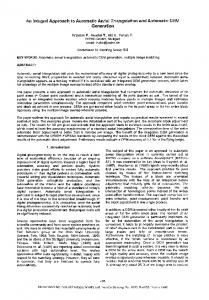
Figure 1: swissphoto triangulation block Switzerland including block Basel, Aargau, Lucerne and Brienz MHz) was used. For the triangulation data in total 36 GByte (4 x 9 GByte) disc storage capacity was available.
photo scale 1: 26’700) the terrain varies between hilly and mountainous (ground height from 380 m to 1800 m), while block Brienz (270 images) represents mountainous and alpine terrain characteristics and height differences between 450 m and 2600 m covering midland to alpine regions. The latter block also includes one strip from a valley flight and large photo scale differences from strip 27 (1: 28'000) to strip 30 (1: 40’000). Flight and block data of the four introduced swissphoto blocks are summarised in Table 1. As mentioned in this Table each block includes flight lines with different exposure times which varied from some days to more than 1 month resp. 1 year (e.g. Block Brienz) and consequently causes vegetation changes from strip to strip.
2.4. Software For the four swissphoto triangulation blocks the software release 3.1.2 of SOCET SET (Softcopy Exploitation Tools) was used. HATS is a module of SOCET SET for performing block triangulation of suitably overlapping images. The tedious process of selecting and measuring image coordinates of pass and tie points is highly automated, with the possibility of operator override. The system flags unacceptable tie points and displays the required images for measurement without operator intervention. All the operator has to do is to re-measure these unacceptable points by moving the floating mark to their proper locations, if requested.
2.2. Digital image data All images were scanned on a Helava/Leica Digital Scanning Workstation DSW200 in RGB mode. The turn around time for scanning each photo was about 30 minutes using a SUN Sparc 20/71. For triangulation the digitised colour images were converted into greyscale images in order to reduce disc space usage. The resolution of the images was 25 µm (1016 dpi), which corresponds to a footprint of approximately 0.7 m on the ground, and the size of each greyscale image was about 80 MByte.
3. DIGITAL AERIAL TRIANGULATION In an automated production, the digital aerial triangulation (AT) is divided into several processing steps, which include data preparation (photos and control points), automatic data import and image minification, automatic interior orientation, automatic AT measurements, GPS supported bundle block adjustment, and quality control. To facilitate the use of the highly automated AT processing modules by the operator some additional software for batch processing and easy-to-use graphical user interfaces (GUIs) were developed by Swissphoto Vermessung AG.
2.3. Hardware The aerial triangulation was performed on a Helava/Leica digital photogrammetric workstation DPW670 (Monostation). As a computer platform a SUN Ultra 2 (167
3
Int. Archives of Photogrammetry & Remote Sensing, ISPRS Workshop, Haifa, Israel, September 9-11, 1997, Vol. XXXII
3.1. Data preparation
and IO determination is approximately 5 seconds per image. The used algorithm is described in Kersten and Haering (1997).
The data preparation includes configuration of the photo block (providing images, loading digital images from tape, if not available on disk) and providing control point data (coordinates, overview plot, available sketches). To obtain sufficient ground control points five different sources are used for all swissphoto blocks: • signalised points from the new Swiss GPS primary network LV’95 • points from additional GPS campaigns • 3-D control points from previous photogrammetric inhouse projects measured on a Leica SD2000 • planimetric control points from cadastre maps at 1:500 - 1:2’000 scale • height control from the Swiss 1: 25’000 map series
3.4. Automatic AT measurements The processes of AT measurements as currently used in HATS are divided into four steps which includes Automatic Points Measurements (APM), Interactive Point Measurements (IPM), and Simultaneous Solve (Remeasurements) and Blunder Detection. Before running APM a tie point pattern was selected and edited to obtain a well distributed point configuration in each image for connecting the block. A very dense tie point pattern consisting of 98 points is used as a standard pattern for all current swissphoto blocks. APM runs as a batch process mostly overnight or during the weekend. On the SUN Ultra 2 APM takes approximately 10-30 minutes per image. After APM a rate of 64-94% successfully measured points could be achieved for the blocks depending on the terrain characteristics, the variation in the photo scale within each block and flight date differences between strips (Block Aargau 94%, Basel 89%, Lucerne 80%, Brienz 64%). Ground control points and additional points were measured with IPM in a semi-automatic mode. If the datum is fixed by measurements of three control points or by GPS camera stations, the program drives the operator to the approximate positions of the subsequent ground control points automatically. After all measurements were performed, the observations were adjusted using the „Simultaneous Solve“ module of HATS. Instead of re-measuring all errors a blunder detection routine eliminates all observations with residuals over a specified threshold. Simultaneous solve and blunder detection were performed in an iterative mode until a certain specified accuracy was obtained. This blunder detection uses only a special threshold criterion and assumes high redundancy in the observations. But with this method it could happen that too many observations, especially between strips, were eliminated due to bad quality of APM. Nevertheless, areas of weak block connections were detected later in the quality control and gaps without any points had to fill by semi-automatic measurements.
For these four blocks signalised points, ground control measured by GPS and height control from the maps were used. The preparation of the ground control is a very time consuming process, which differs from block to block. This part of the triangulation requires the most intervention resp. preparation by the operator. 3.2. Automatic data import and image minification Before starting the measurements, the image import into the photogrammetric station and the minification of the images (building-up image pyramid levels for display and zooming) is performed fully automatically in a batch mode, which takes between 30 and 60 seconds per image on the SUN Ultra 2. The GPS photo centre co-ordinates of each image can be also automatically imported to provide approximate values for the overlaps between images in the blocks. Additionally, the preparation of the triangulation file which contains all parameters for the automatic measurements, can also be performed automatically. Thus using such customisation the operator input is significantly reduced in comparison to when using the unenhanced commercial software package HATS. 3.3. Automatic interior orientation Before starting HATS the interior orientation must be determined for each image. For this, in SOCET Set the first two fiducial marks have to be measured by the operator in a semi-automatic mode, while the rest of the eight fiducials are measured fully automatically. Using this mode it takes approximately 60 seconds manual operator intervention per image. To avoid the time consuming determination of the interior orientation by the operator, a fully operational automatic interior orientation (IO) of digital aerial images was developed at Swissphoto Vermessung AG and integrated into SOCET Set of the DPW670/770 and this can be performed in batch mode without any operator intervention. The IO of an unlimited number of images related to one specifically defined camera type can be automatically determined in one step including quality control. The speed of the measurements
3.5. GPS supported bundle block adjustment All observations (image co-ordinates, control point coordinates and GPS photo centres) were adjusted in a GPS supported bundle block adjustment with self-calibration for each block separately using the bundle block adjustment program BLUH of the University of Hanover. After each run of the bundle adjustment a so called automatic blunder detection was performed to eliminate all image point residuals over a specified threshold. The final bundle adjustment was computed after all residuals over 30 microns were eliminated.
4
Int. Archives of Photogrammetry & Remote Sensing, ISPRS Workshop, Haifa, Israel, September 9-11, 1997, Vol. XXXII
Block
Images
Control H/V
Signalised
σ0
RMS X
RMS Y
RMS Z
[m]
[m]
[m]
[m]
[m]
[m]
control pts [µm]
RMS X0 RMS Y0
RMS Z0
Aargau
152
12/107
5
12.2
0.45
0.44
0.79
0.48
0.40
0.18
Basel
150
80/159
5
11.5
0.59
0.62
0.78
0.37
0.31
0.11
Lucerne
216
22/144
5
11.8
0.55
0.64
1.01
0.59
0.57
0.13
Brienz
270
13/128
3
11.7
0.26
0.31
1.04
0.47
0.34
0.13
Table 2: Results of the GPS supported bundle block adjustments For efficiency reasons the idea of the swissphoto triangulation was to use few signalised control points and many height control points at overlapping strip ends to support the GPS station co-ordinates in the combined bundle adjustment. The results of the adjustments are summarised in Table 2. For all four blocks the root mean square (RMS) values of the control point co-ordinates are better than 0.6 m in X and Y, and better than 1 m in height, while the RMS values of the station co-ordinates are also better than 0.6 m in X and Y, and better than 0.2 m in Z. The σ0 from the adjustment varies between 11.5 and 12.2 micron, which corresponds to better than 1/2 of the pixel size. The precision level of digital AT with automatic digital point transfer depends on the matching algorithm applied and on the pixel size of the digitised images. With feature based matching a precision of 0.30.4 pixels can be assumed for point transfer, while with least squares matching a precision of 0.1-0.2 pixels can be achieved. More details about accuracy considerations of digital AT are contained in Ackermann (1996). Theoretically it should be possible to obtain at least a precision of 1/3 of a pixel using the area based matching algorithm in SOCET SET, which corresponds to 8.3 µm and 0.22 m in planimetry at a photo scale of 1: 27’000. The reasons for the worse results achieved with these four swissphoto blocks could be bad ground control quality (especially the height control from the maps) and the large number of measurements (many tie points with bad quality) in each block which also include residuals larger than one pixel (25 µm). Additional to measurement errors some larger residuals could also be caused by systematic or random errors in the scanner (Baltsavias et al., 1997). The large number of measured points per image provides a higher reliability in the adjusted station co-ordinates. The obtained results are better than the results achieved in the first two test blocks (St. Gallen and Zug) which used a sparse tie point pattern and yielded a few good tie points due to much operator intervention (Kersten and O’Sullivan, 1996b). Nevertheless, the accuracy obtained in the triangulation of the swissphoto blocks is sufficient for automatic digital terrain and orthophoto generation for map scales of 1: 5’000 resp. 1: 10’000.
3.6. Quality control After the final bundle adjustment an update of the orientation data for each image support file and the measured image point files is performed at the DPW670 using interfaces between BLUH and SOCET SET. The geometric quality control for the block is given by the results of the bundle adjustment (σ0, RMS, etc.). Furthermore, due to high automation of the measurements and gross error elimination it is absolutely essential to check the photo connections within each strip and across the strips, in order to confirm a reliable point distribution and connection in the triangulation block. Therefore an additional software module was developed by Swissphoto Vermessung, which provides a fast and easy-to-use visualisation of all point connections in the block (Fig. 2). Using this module the operator is able to scan quickly through the block, photo by photo, strip by strip to check visually the number of rays per point, the distribution of points in each photo, and, by clicking on the photo number in the display window, the connection of each photo (see Figure 2). Thus, the operator is able to analyse the connections within the block and to measure additional points in weakly connected areas. 4. TIME REQUIRED The time required for digital aerial triangulation of each introduced swissphoto block using a customised and modified approach to HATS is summarised in Table 3. In this table only the operator’s time is counted, while the computation time of the computer for running batch processes, which is mostly done over night, is neglected. As the best result a total time of 22 h required for the triangulation of block Aargau, excluding scanning and ground control preparation, was achieved, which corresponds to 8.7 min per image. This block represents an agriculture area with high texture in the photos and with smooth changes from flat to hilly areas, which was ideal for the automatic point transfer and the correlation algorithm. The flight dates of the strips did not differ too much.
5
Int. Archives of Photogrammetry & Remote Sensing, ISPRS Workshop, Haifa, Israel, September 9-11, 1997, Vol. XXXII
Figure 2: Visualisation of photo connections within a triangulation block for quality control triangulation on analytical plotters. We think, that in such areas as represented by block Brienz, semi-automatic point measurements could probably speed-up the triangulation slightly in comparison to the obtained result. The productivity obtained with these four triangulation blocks is a significant time improvement when compared to the results of our first two test blocks St. Gallen (106 images) and Zug (82 images). For these first two blocks HATS was used without modifications to any process and the time required for triangulation was 28 minutes resp. 20 minutes per image for a hilly and mountainous terrain (Kersten and O’Sullivan, 1996b). DeVenecia et al. (1996) report a total working time of around 10 minutes per image, which was achieved with two test blocks using HATS. The two test blocks (Forssa and Wisconsin) have a large photo scale of around 1: 4000 and represent a very flat area with maximal height differences of 10 meters. Beckschaefer (1996) reports about 66 images per eight hour shift as the best result for digital aerotriangulation on the INTERGRAPH ImageStation, which corresponds to a production rate of 7.3 minutes per image.
A slightly worse result (9.8 min per image) with respect to efficiency was achieved with block Basel. This block represents an urban area in the north and forests, agriculture and hilly areas in the south with maximum height differences of up to 1000 m. Particularly the mountain range Jura, with forests and steep slopes, caused some obvious problems for the correlation algorithm. The block Lucerne is at the border of the alpine region in the south and represents agriculture and hilly areas in the north. Therefore, the first part could be triangulated very successfully and quickly, while the second part was much slower and caused some problems due the mountainous areas. Nevertheless, the productivity rate for this block was still 12 min per image. But, the more mountainous areas are represented in the block, the more the productivity rate for triangulation is decreasing due to problems with the correlation algorithm in these areas and due to manual intervention by the operator which was necessary to obtain good quality. These mentioned problems occurred in block Brienz due to some extreme height differences in the alpine region of this block. Additionally, photo scale differences from one strip to the other and the time intervals between the flight dates of the strips (up-to one year) also required the intervention of the operator and consequently reduced the productivity. This block could be triangulated in 22 min per image, which is very close to the time required for
5. ALGORITHMIC ASPECTS The quality of the results and the efficiency of triangulation are dependent on the quality of automatic point transfer and correlation (measurement algorithm), which again depend mainly on image quality (including scan-
6
Int. Archives of Photogrammetry & Remote Sensing, ISPRS Workshop, Haifa, Israel, September 9-11, 1997, Vol. XXXII
AT processing steps
Block Aargau
Block Basel
Block Lucerne
Block Brienz
Preparation inkl. Import, Minif., Int. Ori.
4h
5h
7.5 h
9h
AT Measurements
13 h
16.5 h
29 h
78.5 h
Bundle block adjustment
5h
3h
7h
15 h
Total elapsed time
22 h
24.5 h
43.5 h
102.5 h
Number of images
152
150
216
270
Elapsed time per image
8.7 min
9.8 min
12 min
22.8 min
Table 3: Elapsed time for digital AT using a customised and modified approach (5) The use of on-line triangulation algorithms (sequential estimation in bundle block adjustment and data snooping in blunder detection) during APM to increase the quality of the automatic measurements through elimination of gross errors during the data capture phase (Gruen, 1985a).
ning and weather conditions) and terrain characteristics (e.g. texture and height differences). In summary, the following aspects caused problems for the correlation algorithm in our investigations:
• Extreme height differences in the images resp. block • Strips with different flight dates (vegetation changes in summer) • Shadows from early morning flights (bad quality terrain representation) • Densely forested areas and lakes • Triangulation blocks with variation of the photo scale within the block (from strip to strip)
6. CONCLUSIONS AND OUTLOOK In this paper it was shown that through customisation and modification of commercial triangulation software digital aerial triangulation can be optimised, so that high efficiency can be reached in a digital production environment and the intervention of the operator can be absolutely minimised. The software and interface developments of Swissphoto Vermessung AG, which are introduced in this paper, could speed-up digital aerial triangulation using HATS to a production rate of 8.7 min per image using blocks larger than 150 images and with a photo scale of about 1: 27’000. It could also be shown that excluding automation through batch processing other aspects like terrain characteristics and block configurations (e.g. photo scale differences within a block and different flight dates of the strips) significantly influence the efficiency of triangulation. Compared to conventional triangulation on analytical plotters these presented results demonstrate a significant speed-up in triangulation. Even, if one add scanning time of b/w images (7 minutes per image on a DSW200/Sun Ultra 1 including preparation) to the time required for triangulation per image, digital AT is much more efficient than triangulation on analytical plotters. However, we believe that there is still potential for more improvements in digital AT to increase the productivity so that a triangulation rate of better than 5 minutes per image could be possible in the future, even with difficult terrain characteristics as appear in the Swiss Alps. A much higher productivity rate seems to be very difficult to achieve due to necessary semi-automatic control point measurements and due to the necessary analysis of results from highly automated processes by an experienced operator. Therefore, in the private practice, digital aerial triangulation is on the way to replacing triangulation on analytical plotters in the near future due to higher efficiency.
To improve HATS with respect to speed, precision, robustness, flexibility, and user-friendliness we suggest the following software improvements which are summarised below: (1) The use of an existing DTM in APM speeds up the APM process and increases the precision and robustness significantly, especially in mountainous and alpine regions, so that the rate of successfully measured points can also be increased. In Switzerland, for example, a hectare-raster DTM covering the whole country is available. (2) A particular improvement in increasing the speed of APM would be to measure the tie points only in their two nadir images across strip direction and that the program would then be capable of measuring all other related combinations of this point automatically. This is implemented in the new SOCET Set release 3.2, but it needs more quality control and reliability of the measurements. (3) The implementation of an image matching technique (Gruen, 1985b), which uses two shift parameters as well as two shears and scales, improves the precision of the measurements slightly. A small drawback due to slightly reduced speed should be ignored due to the increasing performance of each computer generation. (4) The use of GPS data, additional parameters and an efficient band ordering algorithm for the re-linearisation of the normal equation system in simultaneous solve leads to more flexibility and speed-up of the adjustment module.
7
Int. Archives of Photogrammetry & Remote Sensing, ISPRS Workshop, Haifa, Israel, September 9-11, 1997, Vol. XXXII
GRUEN, A., 1985b. Adaptive Least Squares Correlation: A Powerful Image Matching technique. Southafrican Journal of Photogrammetry, Remote Sensing and Cartography, Vol. 14 (3), pp. 175-187.
The achieved results of better than 0.6 m in planimetry and 1 m in height is sufficient for the generation of digital terrain models by image correlation and for orthophoto generation with a pixel size of 0.75 m using images with a photo scale of 1: 27’000 and smaller. The points from triangulation (50-100 points per image in average) could be used as an initial DTM to provide rough terrain approximations for automatic DTM generation. A future vision is a fully automatic photogrammetric system, which performs aerial triangulation (including scanning of photographs, import of digital image data, interior orientation, point transfer through large blocks, measurements of control points, bundle block adjustment), and generation of digital terrain models and orthophotos. But we have to be aware that the more automation the systems provides, the more quality control must be implemented between all processing steps - a control which today is carried out mostly by the operator - in order to guarantee accurate and reliable results.
KERSTEN, Th., STALLMANN, D., 1995. Experiences with Semi-automatic Aerotriangulation on Digital Photogrammetric Stations, SPIE Vol. 2646, pp. 77-88. KERSTEN, Th., O’SULLIVAN, W., 1996a. Project SWISSPHOTO - Digital Orthophotos for the entire area of Switzerland. Int. Archives of Photogrammetry and Remote Sensing, Vol. 31 (B2), pp. 186-191. KERSTEN, Th., O’SULLIVAN, W., 1996b. Experiences with the Helava Automated Triangulation System. Int. Archives of Photogr. and Remote Sensing, Vol. 31 (B3), pp. 591-596. KERSTEN, Th., HAERING, S., 1997. Automatic Interior Orientation of Digital Aerial Images. Photogrammetric Engineering & Remote Sensing, Vol. 63 (8). KRZYSTEK, P., 1991. Fully Automatic Measurement of Digital Elevation Models with MATCH-T. Proceedings of 43rd Photogrammetric Week, Vol. 15, pp. 203-214
REFERENCES: ACKERMANN, F., 1996. Some Considerations about Automatic Digital Aerial Triangulation. OEEPE Official Publication No. 33, pp. 157-164.
KRZYSTEK, P., HEUCHEL, T., HIRT, U., PETRAN, F., 1996. An Integral Approach to Automatic Aerial Triangulation and Automatic DEM Generation. Int. Archives of Photogr. and Remote Sensing, Vol. 31 (B3), pp. 405414.
ACKERMANN, F., TSINGAS, V., 1994. Automatic Digital Aerial Triangulation. Proceedings of ASPRS/ACSM Annual Convention, Reno, pp. 1-12.
LUE, Y., 1995. Fully Operational Automatic Interior Orientation. Proceedings of GeoInformatics ‘95, Hong Kong, Vol. 1, pp. 26-35.
AGOURIS, P., SCHENK, T., 1996. Automated Aerotriangulation Using Multiple Image Multipoint Matching. Photogrammetric Engineering & Remote Sensing, Vol. 62 (6), pp. 703-710.
SCHENK, T., TOTH, C., LI, J-C., 1990. Zur automatischen Orientierung von digitalen Bildpaaren. ZPF - Zeitschrift für Photogrammetrie und Fernerkundung, No. 6, pp. 182-189.
BALTSAVIAS, E. P., HAERING, S., KERSTEN, Th., 1997. Geometric and Radiometric Performance Evaluation of the Leica/Helava DSW200 Photo-grammetric Film Scanner. SPIE proceedings, Vol. 3714.
SCHICKLER, W., 1995. Ein operationelles Verfahren zur automatischen inneren Orientierung von Luftbildern. ZPF - Zeitschrift für Photogrammetrie und Fernerkundung, No. 3, pp. 115-122.
BECKSCHAEFER, M., 1996. Practical Experiences with Digital Aerotriangulation based on INTERGRAPH ImageStations. OEEPE Official Publication No. 33, pp. 151-155.
TOTH, C., KRUPNIK, A., 1996. Concept, Implementation, and Results of an Automatic Aero-triangulation System. Photogrammetric Engineering & Remote Sensing, Vol. 62 (6), pp. 711-717.
BRAUN, J., TANG, L., DEBITSCH, R., 1996. PHODIS AT - An Automated System for Aerotriangulation. Int. Archives of Photogr. and Remote Sensing, Vol. 31 (B2), pp. 32-37.
TSINGAS, V., 1992. Automatisierung der Punktübertragung in der Aerotriangulation durch mehrfache digitale Zuordnung. Ph. D. dissertation, DGK Reihe C, Heft 392, München, 110 S.
DEVENECIA, K., MILLER, S., PACEY, R., WALKER, S., 1996. Experiences with a Commercial Package for Automated Aerial Triangulation. Proceedings of ASPRS/ACSM Annual Convention, Vol. 1, pp. 548-557. GRUEN, A., 1985a. Algorithm Aspects in On-line Triangulation. Photogrammetric Engineering & Remote Sensing, Vol. 51 (4), pp. 419-436.
8