Efficient Calibration of Active-Phased-Array SARs Ramón Torres, ESTEC (European Space Agency), Noordwijk (The Netherlands),
[email protected] Manfred Zink, DLR (German Aerospace Center), Microwaves and Radar Institute, Weßling (Germany),
[email protected]
Abstract Calibration of the first space-borne SAR instruments, with only one swath and based on passive antenna technologies, (e.g. ERS-1) required the in-flight characterisation of that single-swath instrument over well-known scatterers (reflectors, transponders and rainforest sensing data). Modern systems evolved to more access flexibility -therefore, multiple beams-, and multi-polarisation that led to the use of complex active phased-array antennas. In-orbit calibration of such complex SAR system can be a very time-consuming and expensive exercise that takes time off the spacecraft lifetime. The full characterisation on ground presents the additional risk of a limited validity if during the early phases of the in-flight operations a number of sub-arrays suffer degradation (i.e. failure of T/R module functions or irrecoverable phase and gain drifts). If this type of degradation occurs, an inflight re-characterisation of the instrument throughout the different beams (i.e. using repeating passes over the rain forest, etc.) is the only way to keep the required accuracy. After the lessons learnt during the ENVISAT ASAR commissioning, this paper present a new concept for SAR calibration built around a mathematical antenna model based on accurate on-ground measurement of the instrument, a set of post-launch external measurements to be performed during the initial commissioning period, periodic in-flight internal characterisation, and the internal calibration data to be taken during and together with the sensing data. Such an accurate antenna model is a very powerful tool both for pre-flight characterisation of all antenna beams, and for in-flight estimation of the actual patterns.
1
Radiometric Calibration
The objective of the SAR radiometric calibration is the achievement of high radiometric performance (typically an overall radiometric accuracy better than 0.5 dB, 1σ). The radiometric uncertainties that calibration should compensate will in general come from: absolute signal and noise levels, relative variations across the field of view, and temporal variations along the operation. Therefore, calibration requires acquiring the knowledge -to the requested accuracy- of the following parameters at the time of radar sensing: • Antenna Radiation Patterns, • Antenna Pointing (i.e. the reference frame of the radiation pattern), • Absolute Gain for absolute radiometry • Variations of these parameters during the data taking (i.e. the short-term Instrument Stability), and • Noise For an active antenna the radiation patterns and the antenna pointing are assumed to be stable in short term, i.e. they are dependent on the characteristics of the sub-arrays, their status, and the overall conditions
of the antenna after deployment. The absolute gain is assumed to vary slightly throughout the data take because of temperature effects and limitations of temperature compensation schemes.
2
Calibration Concept
Traditionally, the calibration of space-borne SAR systems (ERS-1, ERS-2, RADARSAT-1, etc.) has been considered as an in-orbit activity that relied on systematic radar acquisition over uniform-scattering scenes (e.g. rainforest) and required the deployment of well-known point targets (e.g. transponders, corner reflectors, etc). This concept worked very well for such single-mode instruments based on and highly stable passive antenna technologies. The calibration plan was defined independently from the system design and development, was executed during the system commissioning and supported the maintenance of the performance for the lifetime. Evolution to more flexible systems (i.e. multi-beam, multi-polarisation, azimuth scanning, etc.) led to the use of complex active phased-array antennas. Systems like ENVISAT ASAR applied the same calibration concept used for the ERS satellites resulting in a
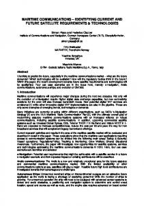
time-consuming and expensive exercise that takes time off the spacecraft lifetime and requires a periodic re-calibration because of the expected sub-arrays degradation (i.e. failure of T/R module functions or irrecoverable phase and gain drifts) in order to maintain the required accuracy. Figure 1 shows the calibration process related to the system design and development, including the characterisation tests that were defined for ENVISAT ASAR to support the system stability.
•
Stable and well-calibrated transmitter and receiver functions to cope with the levels of the calibration signals Stability requirements for the elements that will fall outside the internal calibration network (e.g. radiators, etc.) Characterisation tests with the accuracy required by the calibration plan in order to keep the overall system performance The development of Antenna Model that reproduces accurately the antenna radiation characteristics from the on-ground characterisation and the internal calibration data
• • •
Design
Calibration Plan
Build Assembly Integration Tests
Figure 2 shows how the calibration process interacts with the system engineering process of the system development.
Characterisation
Design Launch
Build Assembly Test / Characterisation
In-orbit Validation Routine Calibration
Figure 1: Traditional Calibration Process
Integration Test / Characterisation Model Validation Launch
New generation of space-borne SARs, also based on multibeam, multipolarimetry, azimuth scanning for spot-light and azimuth-sweep ScanSAR, are required to provide the sensing data in a much more operational basis and precise antenna beam control, for which time-consuming calibration and re-calibration activities are barely acceptable. The proposed system calibration concept incorporates the calibration process up to the system design and development in order to minimise the in-orbit calibration process and avoid the non-operational periods. It is based mainly on the use of on-ground pre-launch characterisation data and in-flight internal (i.e. not required external measurements) characterisation and calibration data. These will be complemented with a short set of post-launch external verification measurements to be performed during the initial commissioning period. This calibration concept requires that the system design is made suitable to the approach and that the characterisation of the critical elements is performed at their development. In particular: • An internal calibration network to be built in the antenna to loop back the internal calibration signals
Calibration Process
Calibration Plan
Calibration Process
In-orbit Verification Routine Calibration
Figure 2: System-integrated Calibration Process
3
Calibration of Parameters
Antenna Radiation Patterns The calibration of the in-orbit antenna beams will be based on an Antenna Model that will be validated during the on-ground pre-launch test activities. The Antenna Model will be built from accurate Embedded Sub-array Patterns and the in-orbit T/R module characterisation. The T/R module characterisation can be based on individual sub-array activation tests or on pulse-coding techniques (PCC) and should agree well with the embedded sub-array tests. Measurements of the antenna passive front end will be necessary to complete the Antenna Model. These measurements will be performed at embedded radiator level: Return loss (S11) and Insertion loss (S21). The validation of the Antenna Model will be done by comparing the results with Near-Field antenna tests of a uniform-illumination test beam (all sub-array T/R modules at maximum gain and equal phase) and a limited selection of the operational beams.
A post-launch verification of the modelled beams will be performed during the commissioning period by sampling selected beams using repeat passes over the rainforest. This verification can only be done for the part of the main beam that corresponds to the swath and can also be used to verify elevation pointing. Ground receiver measurements, providing transmit beam patterns beyond the main lobe can be used to verify the antenna model performance over sidelobes. Antenna Pointing The antenna pointing, i.e. the antenna boresight alignment with respect to the AOCS system of coordinates, is a consequence of the alignment of the various systems of coordinates during on-ground spacecraft integration, the in-orbit deployment of the instrument, and the radiating conditions of the phased array antenna. The Antenna Model will be built with respect to the system of coordinates of the on-ground deployed antenna and will be capable to determine the antenna pointing for every beam with respect to this system of coordinates. The spacecraft AIT alignment will provide the alignment of the antenna reference system to the AOCS system and, therefore, to the in-flight attitude at any nominal mode during operations. In case of deployable systems, deviations from the nominal deployment may cause some variation with respect to the assumed nominal antenna system of coordinates (e.g. planarity, etc.) that would affect the pointing of the antenna beams. Any pointing offset in elevation can be estimated from rain forest measurements using standard beams or special notch patterns with a null in boresight direction. Azimuth pointing bias can be derived from the comparison of Doppler estimates from the data itself with the geometrical ones. Absolute Gain The absolute instrument gain will be obtained from different sources: the pre-launch instrument tests and the in-orbit calibration tests: a) Computed from the Antenna Model and the antenna equipment characterisation data (power levels, VSWR, sub-array gain, etc) b) The Pre-launch antenna beam tests in the NF antenna range: The absolute gain can be measured together with the antenna beam patterns. c) Transponder tests. During the commissioning period gain measurements can be performed by using calibrated transponders and will be to be correlated with the Antenna Model predictions through the internal characterisation (NOTE: This is expected to achieve the highest accuracy.)
Instrument short-term Stability The variations of the instrument characteristics within every data take will be tracked with the Calibration Pulses. These calibration pulses will be routed through the signal and calibration paths for transmit and receive and the two polarisations. The calibration pulses will switch along the antenna sub-arrays at row level and can follow individual row activation or a pulse-coded (PCC) scheme that allows a continuous operation of all antenna sub-arrays simultaneously and a nominal load of the power supply units.
4
Pre-launch Characterisation
The following characterisation tests will be used to construct the Antenna Model, Passive Radiator Insertion Phase and Insertion Loss This test will characterise the passive part of the radiator, which is not included in the calibration loop for either Module Stepping tests or row-based internal calibration. The characterisation is in principle assumed to be performed for each radiator and can be done during the radiator acceptance tests. Low radiator insertion loss and dispersion of the insertion phase and sufficiently high stability of the radiator will be required to control the Antenna Model uncertainties caused by the fact that the radiators are not included in the internal calibration loop. The radiator stability needs to be demonstrated. Radiator Characteristics (Coupling & Return Loss) This test consists of the measurement of the Sparameter m x n matrix of the embedded sub-arrays. The sub-array set-up must be measured in an anechoic chamber facing RAM in order to prevent unwanted reflections from the external surrounding. Embedded-sub-array Tests The embedded sub-array test consists of the measurement of the radiation characteristics of each individual sub-array embedded in its location within the antenna final configuration. The interactions caused by the rest of the sub-arrays are present in the measurement in this set-up. Particular care must, therefore, be taken in order to terminate properly the inactive sub-arrays. Likewise, the radiation tests must be defined with the consideration of the whole antenna as the object to measure and not only the active sub-array. The individual power gain will be compared with the previous characterisation of the passive sub-array radiator and the sub-array characterisation performed at the same instance. The embedded subarray patterns will be referred to the antenna system of coordinates.
Antenna Radiation Patterns In the context of the calibration concept, the full antenna radiation patterns will be used to validate the Antenna Model rather than the set of characterisation data to be used in orbit. Advantages of this approach are: • Only a limited set of beams must be measured, allowing a reduction of testing time from the traditional approach • In case of any sub-array failure in the satellite lifetime, the Antenna Model would simulate the radiation patterns of the operational beams with the same accuracy The antenna radiation patterns measured to validate the Antenna Model will be: • The uniform-illumination test beam pattern (all T/R modules at maximum gain and equal phase) and • A selected set of operational beams The validation must be performed in transmit and receive and, if applicable, the two polarisations. Antenna Gain The antenna gain will be measured together with the antenna pattern tests for the measured beams. The standard methods of the antenna range will be used but range calibration might be used to improve accuracy. The uniform-illumination test beam gain will be used as reference, and the gain obtained for the other beams will be referred to the reference by using the Antenna Model.
5
In-orbit Calibration
The following in-orbit tests are defined to provide the ground processor with the necessary data to achieve the required radiometric accuracy by using accurate antenna patterns generated by the validated Antenna Model. T/R Module Characterisation T/R module characterisation test consist of a measurement through the internal calibration network of the transmit and receive settings and characteristics of the individual T/R modules. This test will be performed for transmit and receive and the two orthogonal polarisations. Pulse coded calibration schemes (like PCC) are recommended as the can be performed under more realistic operating conditions, in particular, concerning the power supply load. Calibration Pulses The calibration pulses will track the variations of the transmit and receive gain of the antenna during each data take. Although the sub-array T/R modules may be compensated for the temperature sensitivity, un-
compensated variations, together with any other variation of the rest of the signal routing will be corrected by the ground processor. Calibration pulses defined at row level using PCC are recommended. The calibration pulses will be routed with the radar signal at the beginning and the end of the data take. Additionally, subsequent sets will be possible to be interleaved with the radar signal on an adjustable basis. The frequency for insertion of calibration pulses will be defined considering the expected variation rate. Rainforest Data Takes Data takes over the rainforest will be used for verification of the Antenna Model with respect to the beam patterns and pointing. In order to consider the possible deviations caused during the in-orbit deployment and the stability of the antenna planarity during the satellite lifetime, in-orbit pointing calibration test will be performed periodically. Absolute Gain with Transponders The in-orbit gain measurement using calibrated transponders is expected to achieve the highest accuracy. The transponders will be required to have very good stability and to be calibrated with high accuracy.
6
Conclusions
The proposed calibration scheme guarantees high radiometric performance of complex SAR instruments even through graceful degradation of active antennas. It reduces the in-flight external characterisation only to the Gain Calibration, and only during the short commissioning period. It reduces the operational costs and maximises the operational lifetime of the satellite. The proposed concept is based on the development of a highly reliable Antenna Model from accurate pre-launch characterisation data that will closely track the instrument operating conditions with the periodic in-flight internal characterisation data. The implementation of this scheme in the GMES Sentinel-1, and the exploitation during its development and operational lifetime, will prove the feasibility of using automated calibration correction in ground processors. The acquired raw products could be automatically calibrated by using: • the calibration pulses (within the same data take) • the automatically updated antenna pattern, as result of the latest TRM characterisation (taken frequently, e.g. every orbit) • the corresponding instrument gain (from the antenna model, as commissioned, and the latest TRM characterisation)