2012 International Conference on Biomedical Engineering (ICoBE),27-28 February 2012,Penang
Efficient Class-E Design for Inductive Powering Wireless Biotelemetry Applications Saad Mutashar Abbas, M. A. Hannan, A. S. Salina Department of Electrical, Electronic & Systems Engineering, Universiti Kebangsaan Malaysia 43600 UKM Bangi Selangor, Malaysia
[email protected]
Abstract—This paper introduces a modified an efficient design for different Class-E power amplifiers suitable to be use in biomedical implantable devices and in biomedical wireless telemetry devices which is usually have a small load resistor (several Ohms) due to its inductive powering. The different Class-E amplifiers operated according to the frequency chart for the medical implant communications service (MICS) 27 MHZ, and industrial scientific and medical (ISM) (13.56 MHZ), and low frequency 125-135 KHZ. The results show that the proposed class-E design could use the same values of C1, C2, L2 for small and optimum load resistor with high efficient more than 80% All these three class-E power amplifiers will be presents in this work and will be simulate with the MATLAB/SIMULINK environment, and for further verification all the circuits will be simulated with electronics workbench MULTISIM 9. Keywords-component; transcutaneous energy transmission; implated devices; switching amplifiers; class-E amplifiers.
I. INTRODUCTION The power amplifier is a very important part in low and high frequency bands. It amplifies the input signal to certain power level, which is transmitting circuits. Power efficiency and optimum power transfer is one of the key factors in the design of the power amplifier. For several reasons Class-E amplifier is widely used in implantable devices and biomedical telemetry system, such as cochlear implant, retinal implant, brain implant, pacemaker and detection of neural signals, due to it requires only one active device (simplest), high power transmission [1], and when used as a modulator, it eliminates the need for a mixer and that consumes the power [2]. Class-E mostly has been optimized for power signals [3]. In this paper we design and investigate Class-E power amplifiers, and we will present three transmission standards which are used in transcutaneous wireless telemetry systems, and in biomedical implants communication service (MICS) standard with standard specifies a frequency which involves a number of allowable frequencies, one of this frequencies is 27 MHz [4][5], the second standard is the industrial scientific and medical (ISM), 13.56 MHz [6], and third standard is the radio frequency edification (RFID) standard for low frequency band 125-135 KHz. The low and high frequencies widely used in transcutaneous wireless telemetry systems because of its
978-1-4577-1991-2/12/$26.00 ©2011 IEEE
characteristics to penetrate water and skin in short range. Most of works and researches describe the design of class-E amplifier for fixed RF load of 50 Ω or 75 Ω, and this is not the suitable case of inductive coupling power which it usually very small and depending of the coils, secondary coil load and coupling link [7]. So in our work we shall calculate the optimal RL.opt by calculating the Cmatch and Lmatch to select the optimal values of C1, C2, L2, and calculate the efficiency in this case, then we replace the RL.opt with a small resistor (which it is suitable for inductive powering) using the same values of C1, C2, L2, to satisfy the condition for high soft switching and optimum power delivery to the implant devices with high efficiency.
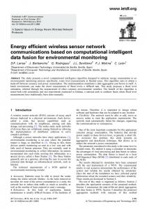
II. METHOD AND SYSTEM FOR CLASS-E AMPLIFIER In general class-E amplifier is widely used in biodevices wireless telemetry and in implantable devices, and it is more suitable power amplifier as an element driver for transmitter coil because of its high efficiency about 90-95% [8]. And when used as a modulator it eliminates the need for a mixer and this minimized the size. The simple class-E amplifier is shown in Fig. 1. Class-E consists of an inductor choke (RFC) to provide a constant current from the power supply VDD, and has no series resistance. Single pole MOSFET transistor switch with a shunt capacitor C2 used to ensure zero-voltage switching of the non-ideal MOSFET switch. This capacitor connected in parallel with a series load network RLC which is tuned to a certain frequency to achieve a constant current from the supply source and converts the digital input signal into a sinusoidal output with zero DC offset. The MOSFET transistor is used as a switch and driven by a periodic pulse which is represented as a series of positive and negative step inputs. The inductive coupling link L2 will be use as a physical coil to transfer data and power to the implanted device through a magnetic coupling [9]. The high efficiency of the class-E can be achieve by reducing the transistor switching losses by using matching network to get optimum resistance. The transistor is turned ON when the drain voltage has come back to zero, reducing the turn ON loss zero voltage switching. The drain voltage is also raised from zero at the time of turning ON which allows for
445
slight returning without losing in the efficiency. The two states of the power amplifier are shown in Fig. 2 which describes the waveforms of the voltage and the current in switching time [10]. III. THEORETICAL MODEL FOR CLASS-E AMPLIFIER AT 13.56 MHZ To reduce the power consumption in class-E amplifier we must satisfy the conditions for soft switching [11]. The matching network given in Fig.3 should be calculated for a certain optimal load RL.opt. The mathematical model for all chosen frequencies was calculated as shown in Table I. The mathematical model for frequency 13.56 MHz will be presented. Suppose that, Pout is 150 mw, f0 is 13.56 MHz, VDD will be 3.3 V, RL (load resistor) is 50 Ω, and the Switch with 50% of duty cycle. For optimum power of class-E amplifier we have to find the optimum resistance RL.opt. Equation (1) is used to calculate the optimum resistance [12].
2
V Pout = ⋅ CC 2 π Rlopt 1+ 4 2
From which, RL.opt= 41.89 Ω (for all the proposed frequencies). To adjusted the source impedance or the load impedance and for optimum power delivery, RL should be converted from 50 Ω to 41.89 Ω by using matching network as given in (2, 3, 4 and 5). Let as consider that Rn = 41.89 Ω and Rm = 50 Ω then
Rn =
Rm X m2 Rm2 + X m
(2)
1 ωo X m
(3)
Rm2 X m Rm2 + X m2
(4)
Cmatch =
Xn =
Xn
Lmatch =
Figure 1. The principle circuit of the class-E amplifier.
(1)
(5)
ωo
To calculate the shunt capacitance (C2) and the series resonance circuit (C1, L2) we assume that ZL (output total impedance) equal optimum load RL.opt=41.89 Ω and the mathematical model to calculate C1, C2, L2 is presented in (7, 8, and 9) [1][13 ]. The MOSFET transistor is selected type (3TEN - 2N7000). For maximum efficiency we must chose the maximum quality factor (Q) must be consistent with the desired bandwidth, and taking into consideration that a high Qfactor of the inductive coil should make the output as close to an ideal sinusoidal as possible, and the very high Q factor reduces the effective bandwidth of the system [14]. So, the choice of Q factor must be realistic according to (6).
Q≤
ωL
(6)
R
In this work the Q-factor for the series resonance branch (C1, L2 and RL) stated in Fig. 1 is assumed to be 10. Figure 2. Waveform of the voltage and current switch conditions.
C1 =
1 ⎤ ⎡π ⎤ ⎡π ωo RL ⎢ + 1⎥ ⎢ ⎥ ⎦⎣ 2 ⎦ ⎣4 2
L2 =
=
1 ωo (5.447 RL )
QRL
(7)
(8)
ωo
⎡ 5.447 ⎤ ⎡ 1.42 ⎤ C2 = C1 ⎢ 1+ ⎥ ⎢ ⎥ ⎣ Q ⎦ ⎣ Q − 2.08 ⎦
(9)
Figure 3. Matching network for class-E amplifier.
446
TABLE I.
COMPONENTS VALUES AND EFFICIENCY FOR ALL PROPOSED FREQUENCIES
L1 (µH) small Resis.
C2 (PF)
L2 (µH)
12
30
51.5
4.92
33.11
1.2
0.65
2.7
14
-
85
150
2.8 nF
F MHz
L1 (µH) opti. Resis.
13.56 27 0.135
82 23 nF
C1 (PF)
η1 %
η2 %
87.2
≥80
73
88
-
94.8
η1 efficiency for optimum resistor, η2 efficiency for small resistor
The transmitted coil Ltr = Ls + L2, where Ls is the excess inductance and it is very small compared with the resonator inductor L2, therefore is ignored in this work, then Ltr ≈ L2 . L1 will be chosen to be 12 µH to have sufficiently large impedance at the center frequency [15]. The efficiency of the class-E power amplifier will be calculated as follow, From the simulation,
the low frequency 135 KHz, it can be used for very small resistors only due to its distortion at high resistance (50 Ω). To achieve the high efficiency of Class-E-PA, it must reduces the transistor’s switching losses, and in order to explain that, we fixed the frequency at 13.56 MHz, and the output waveform was simulated with MATLAB/SIMULINK as in Fig. 6, and with the MULTISIM 9 as in Fig. 7. The frequency 13.56 MHz is so raised to allow high data rate transmission and to avoid the skin damage when it used for transcutaneous wireless telemetry. The supply voltage is 3.3V with 50% duty cycle, and the MOSFET transistor was selected as type (3TEN-2N7000). Fig. 5 shows all the results when used the optimum load and a very small load. Fig. 6 shows the simulation output waveform of class-E with a very small resistor load for all chosen frequencies. The high efficiency of class-E amplifier is achieved by reducing the transistor switching losses, the simulation and results in Fig. 7 shows the output and the Drain-Source voltage (VDS = 0) when the switch is active state (1) and vice-versa where this will reduces the power consumption of the system.
I DC = 27.283 mA , Vrms = 18.1v then
Poutavg =
2 VRMS = 78.28 mW RL
The efficiency of the system is given in (10).
η=
Poutavg × 100% Pin + PDC
The mean of input power
(10)
Pin is very small compared to PDC
Figure 4. Simulation of Class-E-PA using MATLAB/SIMULINK.
( PDC = I DC × VCC ). Therefore it is ignored. So that, the efficiency for class–E with optimum load (RL.opt=41.89 Ω) with operated frequency 13.56 MHZ is 87.2%. IV. SIMULATION MODEL OF CLASS-E AMPLIFIER The module of class-E power amplifier was simulated with MATLAB/SIMULINK environment to evaluating the performance of the CE-PA. This is illustrated in Fig. 4. The same module simulated with Electronics Work Bench (MULTISIM 9) Fig. 5 which shows the simulation at operating frequency of 13.56 MHz using optimum load RL.opt and very small resistor. This design will be used for all different the frequencies (13.56 MHz, 27 MHz, and 135 KHz) with different element values as shown in Table I, with a constant drain supply voltage at 3.3 V for all operated frequencies, and using the MOSFET transistor type (3TEN-2N7000), the components C1, C2, L2, are shown in Table I.
(a)
. V. RESULTS AND DISCUSSION The results in Table I show that we can use the proposed design for optimum resistor and a small resistor with high efficiency (more than 80%) using the same values of C1, C2, and L2 For the proposed frequencies 13.56 and 27 MHz, while
(b) Figure 5. The simulation of Class-E, a- with optimum load, b- small load.
447
.
VI. CONCLUSION
(a)
This paper produced a high efficient Class-E-PA operated with standard frequencies used in biomedical wireless telemetry devices and suitable for inductive coupling links. The operating frequency according to (ISM) 27 MHz. (RFID)13.56 MHz, and low frequency 125-135 KHz. Most of works used the load resistance 50 Ω to 75 Ω, and this case is unsuitable for powering inductive witch required very small resistor also, in this work, we designed class-E amplifier with high-efficiency work with a very small resistors and with optimum resistors to get optimum power delivery to the implant device. All circuits simulated with MATLAB/SIMULINK and MULTISIM 9. It explains the transistor’s losses when we choose the frequency to be 13.56 MHz because of its high data rate transmission for transcutaneous wireless telemetry systems. REFERENCES
(b)
[1] [2]
[3]
(c) Figure 6. Output waveform at (a) 27MHz, (b) 135 KHz, (c) 13.56 MHz.
[4] [5]
[6]
[7]
[8]
[9]
(a)
[10]
[11]
[12] [13]
[14] (b) Figure 7. (a) Drain-Source and Gate-Source in time, and (b) Voltage output signal.
[15]
F. H. Raab, “Effects of circuit variations on the class E tuned power amplifier,” IEEE J. of Solid State Circuits ,vol. 13, pp. 239-247. 1978. A. N. Laskovski, M. R. Yuce, “Analysis of Class-E Amplifier with mixed data Modulation for Biotelemetry,” IEEE 29th international Conference of engineering in medicine and biology socity 2007. Lyon. Franc. M. K. Kazimierczuk, “Class E tuned power amplifier with nonsinusoidal output voltage,” IEEE J. of Solid State Circuits, vol. 21, pp. 575-581, August 1986. FCC Rules and Regulations, “MICS Band Plan,” Table of Frequency allocations, Part 95, January 2003. A. N. Laskovski, M. R Yuce, “Class-E Oscillators as wireless power Transmitters for Biomedical implants,” IEEE 3rd international symposiumon on applied sciences in biomedical and communication technologies. 2010. Roma-Italy M. Kiani, M. Ghovanloo, “An RFID-Based Closed-Loop wireless power Transmission system for biomedical applications,” IEEE journal in circuits and systems, vol. 57, pp. 260-264, 2010. N. Furqan, D. Maeve, “Amplifier design for a biomedical inductive power system,” IEEE 21st international conference on signals and systems. pp. 169-174, Jun 2010. Cork Ireland. N. O. Sokal, A. D. Sokal, “Class-E a new class of high efficiency tuned single-ended Switching power amplifiers,” IEEE Journal of Solid-state circuit, vol. 10, pp.168-176, Jun 1975. M. A. Hannan, A. M. Saad, A. S. Salina, and H. Aini, “Modulation techniques for biomedical implanted devices and their challenges,” Sensors journal, biosensors, 2012, vol. 12, pp. 297-319. T. Suetsugu, M. K. Kazimierczuk, “Analysis and design of class E Amplifier with shunt capacitance composed of nonlinear and linear capacitances,” IEEE journal vol. 51, pp. 1261-1268, 2007. H. Payam, Z. Ying, “A novel high frequency, high-efficiency, differential class-E power amplifier in o.18 um CMOS,” IEEE international conference on low power electronics and design, August 2008. pp. 455-458, Seoul Korea. H. Thomas, Lee, “The Design of CMOS Radio-Frequency integrated ce rcuits,” 2nd edition, communication engineer, vol. 2, pp.4-7, 2004. B. H. Ghazi, D. Mohamed, G. Hamadi, S. Mounir, “Transcutaneous power and high data rate transmission for biomedical implants,” IEEE international conference on design test of integrated system in nanoscde technology. pp. 374-378, Septemper 2008. B. Lenaerts, R. Puers, “Omnidirectional inductive powering for biomedical implants,” (Analog circuits and signal processing) springer 2008. H. Sekiya, Y. Arifuku, H. Hase, J. Lu and Yahagi, “Design of class-E amplifier with any output Q and capacitance on MOSFET,” IEEE European conference on circuit theory and design, vol. 3, pp. 1-2. September 2005.
448
449