EFFICIENT DESIGN OF DPLL SYSTEM FOR WIRELESS COMMUNICATION Sabyasachi Bhattacharyya Student, Electronics and Communication Engineering Don Bosco College of Engineering and Technology Guwahati, India
[email protected]
Ragib Nasir Ahmed
Roushan Saikia
Student, Electronics and Communication Engineering Don Bosco College of Engineering and Technology Guwahati, India
[email protected]
Student, Electronics and Communication Engineering Don Bosco College of Engineering and Technology Guwahati, India
[email protected]
Ripunjoy Sarma
Kaustubh Bhattacharyya Asst. Prof, Electronics and Communication Engineering Don Bosco College of Engineering and Technology Guwahati, India kaustubh.bhattacharyya@
[email protected]
Student, Electronics and Communication Engineering Don Bosco College of Engineering and Technology Guwahati, India
[email protected]
Abstract— For any standard communication setup, an efficient demodulation techniques which not only filters out the high frequency carrier component but also retrieves the transmitted message pulse in a proper fashion with all its properties like amplitude, frequency, phase etc intact is a big necessity. The most important aspect that needs to be taken care of during the design of a communication setup is the instantaneous phase of the signal because the most vital information is stored in the phase of a signal. So, it should be taken care of that the phase of the signal is properly traced at all time so that the user of the setup can receive the message in its proper form without any error. In this regard, this piece of work that proposed here deals with the design of an efficient Digital Phase Locked Loop (DPLL) for use in Wireless Communication. In wireless communication system it is seen that the wireless channel used in the setup has a tendency to distort the shape of the waveform and also effects the phase of the signal at any point of time. Keeping this in mind, we have designed our DPLL system such that it corrects the instantaneous phase of the signal and gives the waveform similar to the message signal Keywords: phase, locked, feedback path, reference signal, Digital
I.
INTRODUCTION
A Phase lock loop (PLL) is a control system that tries to generate an output signal whose phase is related to the phase of the input “reference” signal. It is an electronic circuit consists of a variable frequency oscillator, a phase detector and a loop filter. This circuit compares the phase of the input signal with the phase of the signal derived from its output oscillator and adjusts the frequency of its oscillator to
keep the phases matched [1]. The signal from the phase detector is used to control the oscillator in a feedback loop. Frequency is the derivative of phase. Keeping the input and output phase in lock step implies keeping the input and output frequencies in lock step. Consequently, a phaselocked loop can track an input frequency, or it can generate a frequency that is a multiple of the input frequency. The former property is used for demodulation, and the latter property is used for indirect frequency synthesis [2]. A DPLL is a digital version of the traditional analog PLL systems. It has many distinct advantages over the analog PLL specifically in relation with noise performance and processing complexity. Basically, a DPLL consists of a digital phase-frequency detector realized using XOR gates, JK flip flops etc. Also it consists of a Digital Loop Filter which is designed using the fundamental design procedures for Digital Filters in Signal processing. Also, it consists of a feedback element which is a discrete time version of a Voltage Controlled Oscillator (VCO) also sometimes known as Digitally Controlled Oscillator (DCO) or Numerically Controlled Oscillator (NCO). This feedback element generates the input reference signal and the phase detector detects the difference in phase of the incoming signal and reference signal. The Loop filter is for removing the high frequency randomness. The DPLL thus corrects and locks the phase of incoming signal and the reference signal and due to it the frequencies are also locked giving at the output a replica of the original message pulse but with much improved noise performance and less design complexity.
The report consists of systematically organized sequence of information which describes our work and findings to the fullest. In the next sections, we will mainly discuss the theory involved, the present works in this field, the various design processes we have used, the simulation results and discussion on the results obtained from the system. . II.
THEORETICAL BACKGROUND
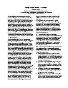
A Digital Phase Locked Loop is a control system that matches the phase of an incoming signal with that of a locally generated reference signal. It completes its operation in a number of iterations and at the end of a series of repeated loops it locks the phase of the incoming signal with the phase of the reference signal that is generated. Keeping the phases in locked condition ensures that the frequencies are also locked. Thus at the output of the loop filter we get our desired replica of the message signal. Conventional PLLs were made of analog components. But in the recent times, Digital PLL’s have emerged as a device with superior characteristics as compared to the analog PLLs. DPLLs can comprise of mainly two types: one with a partly digital and partly analog components i.e. in general with a digital phase frequency detector and a digital divider in the loop and the other one is an All-DPLL consisting of fully digital components [3]. A. Block diagram of DPLL: x(t)
Phase Detector
Loop Filter
Loop Amplifier
v(t)
Voltage Control Oscillator
Figure 1: DPLL Block diagram The following are the components that a DPLL consists of:
Phase Detector: As shown in Figure 1, the phase detector detects the phase difference between the incoming signal and the reference signal. It has been realized using a digital XOR based design. Loop Filter: As seen from Figure 1, loop filter is basically a low pass filter which is used to eliminate the high frequency noise that is incorporated into the signal. The Digital Filter design techniques have been used to realize it.
Local Oscillator: As can be seen from Figure 1, local oscillator forms the feedback path of a DPLL. The oscillator used is a voltage controlled oscillator (VCO) whose input is the output of the loop filter. At the point where the loop filter output is the message signal itself then the oscillator generates a signal matching in phase exactly with the incoming signal and the phases is locked error being nearly zero. A discrete time version of the VCO has been used for the realization of the design. III.
LITERATURE SURVEY
The design and analysis of DPLL has, in the recent times, been a keen area of interest for the researchers and different approaches have been adopted for design an efficient DPLL model. Some of them are discussed here. An Analysis of Digital Phase-Locked Loops, presented by J.B. Thomas, where his work basically focused on design of second order DPLLs with uniformly sampled input and amplitude insensitive phase detector. Basically, the design emphasized on accuracy of output phase and improved performance at high values of gain i.e. high amplitudes [4]. Jefrey Meyer discussed Digital Phase Locked Loop and he had designed two DPLLs laid out in a 0.5μm CMOS process. His analysis was mainly based on use of HDL platforms to get a proper logic design and also CMOS level analysis for an effective layout of the process [5]. Behavioral Time Domain Modeling of RF Phase-Locked Loops, was presented by Sushil Subramanian. The base environment used for this work is Simulink. Here, two things have been mainly focused upon, one is the architectural level synthesis for PLLs i.e. providing a high performance architecture for the PLLs by simulating the various blocks of a PLL and preparing a logic design for them. The other is the analysis of PLLs in non-ideal situations i.e. normally when signals are transmitted; they are subjected to a lot of noisy effects or distorting factors. So, here after development of the system its performance has been analyzed by including such degrading effects [6]. A Digital Phase Locked Loop Based Signal And Symbol Recovery System for Wireless Channel, was presented by Basab Bijoy Purkayastha. This is one of the most recent works carried out in this field. This work mainly focuses on software implementation of the essential components of a DPLL. However, the most valued aspect of this piece of work is that after developing the components of the DPLL, it was tested for QPSK modulated signals and it was found that it had better BER performance than the existing PLL technology thus giving a breakthrough in this field [3].
Jason Chiu discussed PLL component design and this work deals with the PLL component design from a control point of view. It is desired to be able to predict the behavior of the PLL in terms of stability and locking to specified frequencies. Control theory can give us this behavior of a system once we model it in the frequency domain [7]. IV.
b.
DPLL DESIGN
During the designing of the DPLL system, we have mainly focused on digitization of the different blocks that are required for it. In this section, the design procedure for the different blocks of DPLL has been mentioned in details:
|H(jω)|2 =
Ωp =1 and Ωs=ωs / ωp
Phase Detector: The time domain analysis basically consists of two parts: multiplier and a filter [3]. The signals that are input to the multiplier are: x i (t) = Ai cos(2πfct + θ(t))
(1)
xref(t)= Aref sin(2πfct + Фi(t))
(2)
Now, the output of the multiplier will be
Now,
(8)
(9)
And, now the equation (8) can be written as : (10) where, ωp is the normalizing factor, D2n is the square of ripple factor and n is the filter’s order.
c.
x m(t)= kd Aref Ai cos(2πfct + θ(t)) sin(2πfct + Фi(t)) (3)
ω
Equation (8) gives the the impulse response of the Butterworth filter. Now, on normalizing the ω with respect to ωp we have the pass band and stop band of the filter as:
A. Mathematical Modelling: The mathematical explanation for each block is shown as below: a.
sinθ is high. Again, when the phases are locked then the value of sinθ follows: lim sin θ = θ (7) θ->0 Loop Filter: The loop filter is basically a digital Low pass filter that is used to eliminate the high frequency noise added in the channel [4]. In our filter design we have used IIR Butterworth filter. The main equations that describe the Butterworth LPF response are:
Voltage Controlled Oscillator: While designing the feedback path we have used the voltage controlled oscillator and the equations governing the principle of a VCO are: ftuning (t) = K0 vin(t)
xm (t)= (Ai Aref kd /2 ) x 2 cos(2πfct + θ(t)) sin(2πfct + Фi(t)) (4)
(11) (12)
where,
Therefore,
is called the oscillator gain. Its unit is hertz per volt.
x m(t)= (Ai Aref kd /2 ) x [ sin(2ωct + θ(t) + + Фi(t)) – sin(θ(t) - Фi(t)) (5)
Ko
where, kd = constant of the multiplier.
ftuning(t) is the symbol for the time-domain waveform that is the VCO's tunable frequency component
In the phase detector there is a filter or window used to eleiminate the high frequency component, so, the final output from the phase detector is: x pd(t)= – sin(θ(t) - Фi(t))
(6)
Equation (6) gives us the measure of phase difference between the two signals. When there is difference in phase it is reflected as the value of
out is the symbol for the time-domain waveform that is the VCO's output phase.
Vin is the time-domain symbol of the control (input) voltage of the VCO; it is sometimes also represented as vtune(t).
B. Experimental Details The design procedures adopted and experiments conducted for different modules are as mentioned below: a.
Phase Detector: A digital version of the traditional phase detector has been designed:
b.
We consider a Low Pass filter of IIR response and Butterworth Type. The high frequency noise is eliminated from the bipolar signal leaving behind the desired message signal. The signal thus obtained is converted to square wave form so that it can be compared to the desired pulse. The output of the Loop Filter acts as control input for the VCO.
Figure 4:o/p of phase detector Figure 5: o/p of the VCO
Discrete time VCO: We have considered a discrete time version of the traditional VCO:
The loop filter output is fed as control input to the VCO. It generates the reference signal. Its output is fed to phase detector. At some point of time, when the control input is identical to the message pulse, then the phases of the incoming and reference signal are locked.
C. Results And Discussions The output waveforms for the different modules of the DPLL are shown as below and some key observations have been mentioned : a)
Figure 2: Input Data stream Figure 3:Input Signal to the DPLL
Loop Filter: A digital Low pass filter has been designed to serve as a digital block for DPLL:
c.
Firstly the incoming signal has been converted to a square wave pulse. The VCO provides the reference signal. A XOR based design has been adopted for the detection of phase. It detects the phase match- mismatch in terms of ‘0’ and ‘1’. Finally, the result is back converted to a bipolar pulse.
Waveforms:
Figure 6:o/p of the loop filter (DPLL) b) Observations: The input to the DPLL phase detector is of analog form. After having passing through the channel, it is incorporated with noise and so proper treatment is required for reconstructing the message signal as shown in Figure 3. As shown in Figure 4 the phase detector provides a digital pulse indicating ‘1’ the time instants where phases match and ‘0’ when they don’t match. The discrete VCO we have designed also provides a digital signal. When the phases are
V.
locked, this reference signal is same as the incoming pulse in digital form as shown in Figure 5. The loop filter output provides the output of the DPLL which is a replica of the original message signal as shown in Figure 6. We have seen from Figure 2 and Figure 6, both the pulses are identical. Thus the DPLL gives us satisfactory results as it is able to extract the original message that is transmitted. However, there is a delay between the input and output pulses due to the net propagation delay of the system.
B. DPLL Based Wireless Communication Links: The communication system that we have designed consists of mostly the fundamental components that are present in a general communication setup as follows: a.
VCO based transmitter: As we know, Voltage Controlled Oscillator (VCO) can be used for frequency translation and modulation purposes [6]. So, we have designed the transmitter section using the VCO.
b.
Channel: The signal has been passed through the Additive White Gaussian Noise Channel at optimum values of SNR and the performance of receiver has been found to be satisfactory as can be seen from Figure 3.
c.
DPLL receiver: The DPLL system that we have designed serves as the stand-alone receiver for the link. It performs the desired phase correction and at the output it provides the reconstructed delayed version of the original message signal as can be seen from Figure 2 and Figure 6.
DPLL IN WIRELESS COMMUNICATION
The DPLL system that we have designed, besides having various other uses, has great scope in the field of Wireless Communication. The system fits in perfectly to serve as the Receiver of a modern day wireless communication link. The need of DPLL and its implementation in wireless communication has been discussed in this section: A. Necessity of DPLL: Radio waves propagate from the transmitting antenna and move through free space and therefore undergo some critical phenomena like reflection, absorption, scattering etc due to the elements of atmosphere. Besides, very often there exist structures which are taller than the transmitting towers and when waves strike these, signal gets splitted into different components and propagate through different paths. Thus, at the receiver, these different components of the same signal reach at different times which leads to a timing difference and ultimately to a phase difference between the components. Now, the net signal is a combination of all these components and therefore due to mismatch in phase of the components, there is a fluctuation in the instantaneous phase of the radio signal. This variation in phase in turn causes fluctuations in the time varying amplitudes of the received signals and gives a fading effect to the signal which is called Multi-path fading [8]. Now, in order to minimize or control this degrading effect, we need to have a system for correction of instantaneous phase of the incoming signal. And in this situation, our DPLL system can be used in the receiver section of the link as it can perform satisfactory phase correction of incoming signal and thereby helps in proper reconstruction of the original message pulse.
C. Advantages of DPLL Based Wireless Communication System:
All the components involved are digital and thus provide high immunity to supply voltage noise. Besides high immunity to temperature variation. Bulky loop filter components like resistors and capacitors are no longer required. DPLLs can be designed using Hardware Description Language (HDL) and thus time for redesign and troubleshooting is reduced [9].
D. Limitation: The DPLL system that we have designed although gives satisfactory results in terms of phase locking but it has a limitation that its working is limited to the link that we have established and the system is not found to be equally effective in when tested under some of the other standard systems like the M-PSK system, ASK etc. However, with a bit of analysis and certain small modifications in the design its performance can be improved for these standard systems as well. CONCLUSION
Based on our above discussion, we can conclude that the DPLL is a very efficient system and when introduced as a
standalone receiver in a standard communication system, it yields very satisfactory results specifically in terms of its noise performance. Thus, it has become very popular now days and is an obvious choice in most of the communication setups. Moreover, it being a stand-alone device and comprising of some of the most fundamental digital components, it can easily be designed for other purposes except communication. In this regard, the DPLL finds wide applications in clock recovery process, distributed clock distribution for CPUs and a number of other useful tasks. Thus, it is a device having huge significance in the field of modern day electronically controlled systems. ACKNOWLEDGEMENT In this section we would like to thank Mr. Kaustubh Bhattacharyya, our guide and Faculty, Department of Electronics and Communication Engineering, Don Bosco College of Engineering and Technology for his continuous guidance during the preparation of this piece. We also want to thank all the teaching and non-teaching staff of our Department and also our colleagues for their valuable inputs which helped us to enhance the standard of our work. REFERENCES [1] Simon Haykin: “Communication Systems”, Fourth Edition, Wiley India Edition, 2011. [2] B.P. Lathi: “Modern Digital and Analog Communication System”, International Fourth Edition, Oxford, 2011. [3] Basab B. Purkayastha and Kandarpa Kumar Sarma: “A Digital Phase Locked Loop for Nakagami-m Fading Channels using QPSK Modulation Scheme”, 2nd IEEE National Conference on Computational Intelligence and Signal Processing (CISP-2012), Guwahati, India, pp. 140-145 (2012). [4] J.B. Thomas: “An Analysis of Digital Phase-Locked Loops”, JPL Publication89-2, National Aeronautics and Space Administration (NASA), pp. 10-16 February 1989. [5] Jeffrey Meyer: “Modelling Phase-Locked Loops using VERILOG”, 39th Annual Precise Time and Time Interval (PTTI) Meeting, pp. 1-10. [6] Sushil Subramanian: A Thesis on “Behavioral Time Domain Modeling of RF Phase—Locked Loops”, Department of Electronics and Electrical Communication Engineering, India Institute of Technology, Kharagpur, pp. 15-21, May 2009. [7] Jason Chiu: “PLL Component Design”, UW ASIC Analog Group
[8] S.M. Elnoubi and S.C. Gupta: “Performance of First-order digital Phase-Locked Loops in Mobile Radio Communication”, IEEE Trans. Commun, vol. COM-33, pp. 450-456, May 1985.
[9] R.B. Staszewski, J.L. Wallberg, S.Rezeq, C.M. Hung, O.E. Eliezer, S.K. Vemulapalli,, C. Fernando, K. Maggio, R. Staszewski, M.C. Lee, P. Cruise, M. Entezari, K. Muhammad and D. Leipold: “All-digital PLL and transmitter for mobile phones”, IEEE J. Solid State Circuits”, vol. 40, pp. 246-248, December 2005