Lee Freitag, Mark Johnson and Milica Stojanovic*. Woods Hole Oceanographic Institution, Woods Hole, MA. *Northeastern University, Boston MA.
Efficient Equalizer Update Algorithms for Acoustic Communication Channels of Varying Complexity Lee Freitag, Mark Johnson and Milica Stojanovic* Woods Hole Oceanographic Institution, Woods Hole, MA *Northeastern University, Boston MA
Abstract-Underwater acoustic communication channels vary from stationary with sparse arrivals to rapidly varying and fully reverberant. A receiver structure capable of operating over this wide range of characteristics has evolved in recent years and consists of a fractionally-spaced multi-channel combiner, a sparse DFE, and an embedded PLL. At the computational heart of this receiver is an adaptation algorithm, used to update the various equalizer parameters. The adaptation algorithm may use one of the standard strategies such as adaptive step-size LMS, RLS, adaptive memory RLS, or a hybrid of these. The choice of algorithm involves trade-offs between training time, tracking-rate, operating SNR, and computational requirements of the receiver. To maximize the receiver throughput, we wish to select the least computational algorithm for which the errorrate is still acceptable and, given the volatility of the underwater channel, this choice should be made for each received packet. In this paper, we compare the performance of several LMS and RLS adaptation algorithms over a range of real acoustic data. We show that the computationally-efficient adaptive step-size LMS performs well for many channel classes, but that the faster tracking of RLS is essential for some complex non-stationary channels. The results provide a first step towards the automatic selection of adaptation algorithm, as would be required in a fully autonomous receiver.
I. INTRODUCTION Compared to many other communication media, underwater acoustic channels are generally bandlimited and so involve relatively low data rates. Despite this, the channel distortions commonly encountered require complex signal processing in the receiver, resulting in high computational loads and the need for power-hungry, high-speed DSP hardware. Consequently, the design of a computationally-efficient receiver is crucial for practical implementations. The problem of reducing receiver complexity may be addressed on two levels: (i) in the design of an efficient parametric receiver structure, and (ii) in the choice of an efficient algorithm to adapt the receiver parameters. The receiver structure considered here has been developed over several years and consists of a multichannel DFE with fractionallyspaced feedforward filters and an embedded phase-locked loop [ 1][2]. This receiver is able to decode coherently-modulated data in difficult acoustic environments at a wide range of frequencies and data rates [ 1][3]. A number of modificaThis work was supported i n part by the Defense Advanced Research Project Agency under contract MDA972-95-0006 and by the Office of Naval Research under N00014-95-1-0496
tions have been proposed to further reduce the receiver computational load, including an improved phase-locked loop, sparse DFE parameterization, and efficient resampling to compensate for Doppler-induced time dilation 131. The receiver may use any of a number of adaptive algorithms for adjusting its parameters, although typically an algorithm from the LMS or RLS families is selected [4]. LMSbased algorithms have been prefenred in several recent studies due to their low computational complexity, which is linear in the total number of parameters, N [5][6][7]. However, in a fully-developed multipath environment, N may be very large (more than 100) and this can lead to an unacceptably long convergence time [4]. In addition, the performance of LMS is very sensitive to the choice of step-size. To overcome this latter problem, self-optimized LMS algorithms [5][8] have been used at some cost in complexity. RLS algorithms, including the square-root version which is well suited for single-precision implementations [9], have better convergence properties than LMS but much higher computational complexity. Indeed, the quadratic complexity of standard RLS [4] is infeasible for real-time applications when N is much larger than 100. This has led to interest in the family of ‘fast’ RLS algorithms having linear complexity. Unfortunately, such algorithms typically suffer from high numerical sensitivity and have reduced flexibility of application, relying upon a shifting property in their input signals [lo]. Although a numerically stable fast RLS algorithm [lo][ 111 has been used for multichannel equalizer tests in offline processing [2], it has an awkward trade-off between tracking rate and numerical stability which tends to limit its application. The preceeding comments underscore an inevitable tradeoff adaptation algorithms with low computation rates are less able to decode highly distorted data than their more complex counterparts, and so in the rapidly-varying underwater channel, the best choice of adaptive algorithm, from the combined viewpoint of computational efficiency and accurate decoding, may change on a packet-by-packet basis. The aim of this paper is to compare the performance of several LMS and RLS algorithms with real acoustic data in an effort to establish under what conditions LMS may be acceptable. The paper is organized as follows: in Section I1 the structure of the DFE and the different update algorithms are intro-
I ~
0-7803-4108-2/97/$10.00 0 1 997 IEEE
580
Authorized licensed use limited to: TELECOM Bretagne. Downloaded on February 11, 2009 at 03:41 from IEEE Xplore. Restrictions apply.
where X i S kis an r-vector of observations at time k for the ith hydrophone, pre-processed so as to remove a majority of the effects of Doppler shift and converted to baseband. D,, is the m-vector of previously decoded symbols used for decision feedback. The estimate, i i k , of the next data symbol, dk, is computed using the current parameter vector:
X
ak=
H
Ok @k
where 0,is the vector of length: 8,.
N = p+ Recovered Data
cni i = l
collecting all of the adaptive parameters in the equalizer. The transmitted symbol is deduced from a k by:
A -ie, dk= e Decision { e a,} Figure 1 . The DFE with m input hydrophones, m fractionally-spaced ( r samples per symbol) feedforward filters and single phase-locked loop implemented at the summing junction of the feedforward and feedback sections. The error signal ek is provided to an adaptive filter algorithm of choice which updates the weights as well as maintains state as required.
duced and issues which influence the selection of a particular algorithm are discussed. In Section I11 the performance of the different update algorithms are compared using data from atsea tests, both easy and challenging, and conclusions drawn about both efficiency as well as overall robustness. 11. EQUALIZER STRUCTURE AND UPDATE ALGORITHMS
The equalizer algorithm, shown in Fig. 1, contains a DFE augmented by fractionally-spaced ( r samples per symbol) input filters for each of m channels and coupled with a phaselocked loop operating to track the joint phase estimate. With this structure, the regressor vector, used to adapt the equalizer parameters, consists of r new observations for each channel at each iteration which are added to a total of ni parameters for each feedforward filter. The regressor vector is thus: I-
-!
'1,
k
"I
1. k - +
'm. k
X
n m,k-2
-
'k-1
.
(4)
The error is then computed as: ek = d k - Z k
and the PIALupdated as
where: g (1.1 - 4 - 5 G(q-') =
1-29
-1
+g
-2'
(7)
Lastly, the equalizer parameters are updated with the adaptive algorithm:
O,, 1= Update (O,, Ok,e k ) .
(8)
This adaplation step dominates the computational cost of the receiver and also determines many of its performance properties. Of particular concern are the effect of update algorithm choice on the convergence-rate and operating SNR of the receiver, and these are discussed in turn in the following. The convergence rate of the update algorithm is a function of the number of parameters, N, and the richness of the input signals. For reasons of bandwidth efficiency, it is desirable to have rapid initial convergence of the equalizer. However this is difficult to achieve with LMS algorithms if N is large or if there is substantial spectral disparity in the received signals (e.g., due to multipath arrivals). Because of its second-order structure, the convergence rate of RLS is much less sensitive to the input signal quality and N although numerical stability can become an issue in extreme cases. The minimum SNR for which decoding is possible at the receiver is determined in part by the misadjustment noise of the update algorithm. Misadjustment is due to the tracking behavior of the algorithm and there is an unavoidable tradeoff between fast tracking and misadjustment noise. For a giv-
581 Authorized licensed use limited to: TELECOM Bretagne. Downloaded on February 11, 2009 at 03:41 from IEEE Xplore. Restrictions apply.
vessels in 100-200 m deep water was processed with this algorithm. The acoustic channel varies from extremely simple, with high SNR and only a few arrivals, to low SNR with a long and sparse response. The optimal step size (Fig 4) varies by more than 4 over the test At the beginning it is approximately 0.02 however, as the range increased and more parameters are needed by the equalizer (and SNR decreases), p drops below 0 005 The RLS algorithm with adaptive memory [8] is based on the direct form, version I1 [4] The algorithm requires additional computations for the derivative of the inverse correlation matrix:
en tracking rate, the misadjustment tends to increase linearly with N and so becomes an important limiting factor where the channel complexity is high. In such cases, adaptive stepsize algorithms which dynamically adjust their tracking rate so as to minimize the MSE, offer an important advantage. In the following section, we consider an LMS and an RLS implementation of (8) and compare the resulting performance.
111. COMPARISON OF LMS AND RLs ALGORITHMS It is difficult to fairly compare algorithms that can optimally adjust their tracking parameters with those that are fixed, so in order to compare RLS and LMS the adaptive versions of each are used. While the adaptive step-size LMS has been presented in [ 5 ] for use in underwater acoustic communication, the adaptive-memory RLS has not yet appeared in the literature for this application.
the gradient: H
Wk+i = ( I - K Q k ) W k ' S k @ ) k e k and the time-varying forgetting-factor:
A. The A d a p t i v e Algorithms
'
Yk+, = (l-pk@k@k
H
) Y k + Q k e ; and
(9)
(10) where CL is a small learning-rate variable. As written, the 2 update Y , + is 0 ( n ) so it is re-ordered as H
(11)
'@ke*k.
To demonstrate how the optimal step-size changes over time, an hour of transmissions between two slowly moving
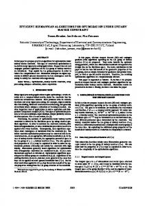
LMS Performance with RLS Initialization
Total Equalizer Parameters
70
-
I
I
A
A
A
I
30 0
01
02
-5 -
03
04
0.5
(14)
where a is the learning coefficient and the forgetting factor is limited over the range 1 m,n < hk < h m a x . While this algorithm is computationally intensive, it is a useful tool for benchmarking RLS-based equalizers and it provides the best ulhmate performance over a variety of channels. One of the main drawbacks of the LMS algorithm is the potentially long convergence time. However, it is possible to utilize a simple hybrid of RLS and LMS to speed training and yet track efficiently. To accomplish this the RLS (direct form) is used for training and then the update task is taken over by the LMS algorithm. Since the LMS load is quite small in
= p k + aRe ( $ @ k e k )
= Yk-pk@k(45k
H
hk+ 1 = hk a R e (U' k @ke*k)
The LMS algorithm with adaptive step size requires computing the time-varying step-size pk and the gradient estimate Y,. These are given by [SI:
pk+ 1
(13)
0.6
0.7
0.8
I
' 7 11
F
0.
I
w Average of Adaptively Computedp 0 025 P
-10 -
I
-15-
0'
0
01
02
03
0 4
05
06
07
08
-20 I
I
0
Fig 2 LMS step-size determined adaptively by the self-tuning algorithm of equations 9-10 for one hour of moving source-receiver testing in coastal waters
I 500
1000
1500
2000
2500
3000
Time (symbols)
Time (hours)
Fig 3 Performance of the RLS-LMS algorlthm The training period of LMS IS almost 2000 symbols wkle the RLS convergences i n about 500 The transition from RLS to LMS occurs at the 500 symbol point
582 Authorized licensed use limited to: TELECOM Bretagne. Downloaded on February 11, 2009 at 03:41 from IEEE Xplore. Restrictions apply.
comparison to RLS, both are run in parallel during the training period with the RLS-computed weights provided as input to thc adaptive LMS. Fig. 3 shows an example of this, the LMS by itself has a long convergencc time, but when provided with the RLS parameters after training is capable of tracking for the remainder of‘the packet. B. Experimental Result3 The algorithms are compared using data that represent a number of different realistic underwater acoustic channels. In all cases the signals are 1250 symbol per second QPSK centered at 2.25 kHz. To detect the start of a packet a 13-chip Barker code is sent prior to the data. The Barker code provides approximately 1 1 dB of gain after match-filtering for the impulse response plots shown in this section. The transmitted signals were received on vertical arrays and processed using one to fifteen hydrophones to demonstrate the performance provided by multi-channel receivers. The deep-water data is from an array with 6.6 m element spacing, the shallow water tests were conducted using 1 m spaced hydrophones. The first case is from a 40-km deep-water test with the array located at 750 m. As may be seen in Fig. 4-A, the channel response consists of two closely-spaced rays which span only a few symbols. The overall performance of both update algorithms is essentially identical for one to fifteen channels. The second example (Fig. 4-B) is taken at 30 km range in 200 m water on the New England continental shelf. The impulse response spans about 60 msec (75 symbols) and while there are a number of ways to parameterize this channel (selection of feedforward and feedback tap lengths), here the width of the feedforward section is fixed at 12 taps per channel and 50 parameters are used for the feedback filter. The adaptive RLS enjoys a clear performance advantage here, up to 5 dB, depending on the total number of channels used. In this case the LMS has both a longer training period and the total misadjustment error after training is larger than that of the RLS. However, despite this difference the LMS algorithm easily provides adequate MSE for QPSK and 8-PSK data transmission. The third case (Fig. 5 ) is taken in the same acoustic environment as the previous one but at a range of 45 km. The impulse response has doubled in length and is now strongly acausal. For each hydrophone channel 40 feedforward taps are used and the number of feedback taps is fixed at 80. The large number of resulting parameters (up to 700) makes adaptive-memory RLS computationally prohibitive and the direct form RLS with constant forgetting-factor is used instead. Despite the complex impulse response and deep spectral nulls the LMS algorithm is fully capable of providing parameter updates which adequately track this channel and provide low error-rate communication. As the number of parameters grows the performance difference between the two algorithms narrows, and ultimately LMS surpasses RLS by about one-half dB. It must be borne in mind that this differ-
ence results, from use of fixed-memory RLS: for optimal performance the forgetting factor should have been reduced slightly as the number of parameters was increased. While the adaptive LMS algorithm provides good performance in the three cases discussed above, when the channel is changing rapidly the tracking ability of the adaptive LMS may not be sufficient to maintain the MSE needed for proper DFE operation. An example of this is shown in Fig. 6 where a channel complexity similar to that of Fig. 5 is combined with time-varying effects. The LMS MSE is too high for error-free operation and the DFIi diverges when the channel begins to change rapidly. In contrast, the additional 2 dB of performance gain available with the RLS (operated here with fixed forgetting factor) allows error-free opera ti on.
IV. CONCLUSION The performance of LMS and RLS adaptation algorithms in a multichannel DFE has been compared using at-sea data. The data provided a range of underwater acoustic channels from relatively benign to extremely challenging. For simple channels, for which few adaptive parameters are required, LMS and RLS update algorithms show very similar results. However, as channel complexity grows, the performance of LMS degrades with respect to RLS, most inotably in terms of convergence rate but also due to the increase:d misadjustment noise of LMS. The slow convergence rate of LMS can be overcome for stable moderate complexity channels by using RLS during the training period and then switching to LMS for the remainder of the packet. When the total number of parameters increases to many hundreds, as required in the most complex channels, the performance of LMS is only acceptable where the channel is relatively stationary. In such cases, LMS offers reasonable performance at a tremendous computational savings over the direct form RLS. However, in cases where high complexity is combined with nonstationarity, the extra tracking capability of RLS can make the difference between success and failure for the DFE. Thus, unfortunately, some of the most complex channels require the more computationally intensive update algorithm.
REFERENCES M. Stojanuvic. J. Catipovlc and J. Proakis, “Adaptive multichannel combining and equalization for underwater acoustic communications,” J. Acousr. Soc. Am., Vol. 94, (3), FYI, pp. 1621-1631. Sept. 1993. M. Stojanovic, J. Catipovic and J. Proakis, “Phase coherent digital communications for underwater acoustic channels”, IEEE J. Oceunic Eng., Vol. OE16, pp 100-111, Jan. 1994. M. Johnson, L. Freitag and M. Stojanovic, “Improved Doppler Tracking and Correction for Underwater Acoustic Communication.” in Proc. ICASSP ‘97, vol I . pp.575-578, Munich, Germany, April. 1997. S . Haykin, Adaptive Filter Theory, New Jersey: Prentice Hall. 1986. B. Geller, V.Capellano. J.-M.Brossier, A.Essebar and G.Jourdain, “Equalizer for video rate transmission in multipath underwater communications,” IEEE J.Oceunic Eng., vol. 21, pp.150-155. Apr. 1996. B Woodward and H.San. “Digital underwater voice communications,” l E E E J . OceunicEng. vol 21. pp.181-192, Apr. 1996.
583 Authorized licensed use limited to: TELECOM Bretagne. Downloaded on February 11, 2009 at 03:41 from IEEE Xplore. Restrictions apply.
Array Impulse Response
Single Channel PSD 10
I
-1 5
-20 -1000
-500
Time (sec)
ch7
0.005
0.01 5
500
-2
I
\
-18
Time (sec)
4 6 8 10 12 Number of Hydrophone Channels
Array Impulse Response
Single Channel PSD
0.01
1000
Update Algorithm Companson
Single Channel Impulse Response
0
0 Frequency (Hz)
0.02
2
-500
-1000
Time (sec)
14
1000
500
0
Frequency (Hz) Update Algonthm Companson
Single Channel Impulse Response
-5
3
Adaptive Step-Size LMS
-lo
W
v)
-15
-
or E
a -20 I -25
Time (sec)
i
Adaptive Memory RLS -
2
L
_ . l -
I.-
-
I
L
4 6 8 10 12 Number of Hydrophone Channels
. L.
14
Fig 4 Performance of the adaptive memory I U S and the adaptive step-size LMS algonthms under two different channel conditlons (A) The 40 km deepocean channel with a simple impulse response For each feedforward filter 6 taps are used and the number of feedback parameters IS fixed at three Thus as the number of channels increases from 1 to 15 the total number of parameters goes from 9 to 93 and performance for both algonthms increases as well (B) The 30 km shallow water (200 m) New England continental shelf In this example 12 feedforward filter taps are used per channel and the number ot feedback parameters is fixed at 50. Here the parameter range is 62 to 230 Here the high SNR and deep spectral nulls provide the RLS with a large performance advantage
5 84 Authorized licensed use limited to: TELECOM Bretagne. Downloaded on February 11, 2009 at 03:41 from IEEE Xplore. Restrictions apply.
Array Impulse Response
Single Channel PSD 10
-
0
%
g -10 3 ._ a L
$ -20
-30 -dn
-1000
0
-500
500
1000
Frequency (Hz) Single Channel Impulse Response
Update Algorithm Comparison
ch5
0 -
I
P
h
-2
g $
-4
-6
H
111
P01 >
-8 t -10
-12 -14
0.1 Time (sec)
0
1
2
0.2
6 Number of 4
I
I.
8
10
I
L
12
14
Hydrophone Channels Fig. 5. Algorithm performance at over 45 km in shallow water. The total impulse response spans, about 125 symbols (250 T/2 taps). Here 40 feedforward filter taps are used per channel and the number of feedback parameters is fixed at 80. The parameter range shown in the lower left is thus 100 to 700 as the number of channels is increased from 1 to 15. The large number of parameters precludes the use of the adaptive memory IUS and the fixed version is used instead. Thus as the number of parameters increases and the forgetting factor should have been decreased, the performance difference narrows and finally the adaptive LMS offers improved performance. This illustrates the difficulty of maximizing performance with constant adaptation rates. [7] G S Howe et a1 , “Sub-sea remote communications utilising an adaptive receiving beamformer for multipath suppression,” in Proc OCEANS’94, pp 1313-1 316, Brest,France, Sept 1994 [8] A Benvemste, M Metivier, and P Pnouret. Adaptive Algonthms and Stochastic Approximations Berlin: Springer Verlag 1990 [9] F Hsu, “Square root Kalman filtering for high-speed data received over fading dispxsive HF channels,”IEEE Trans Inform Theory, Vol IT-28, pp 753-763, Sept 1982 [IO] D Slock T Karlath, “Numencally stable fast transversal filters for recursive least squares adaptive filtering,” fEEE Truns B g Proc , rol SP-39, pp 92- 114. Jan 199 I [ 111 D Slock. IL Chisci. H Lev-An and T Kailath, “Modular and numericall) stable fast transversal filters for multichannel and multiexperiment IUS.” IEEE Tram Sig Proc , Vol 40, pp 784-802, Apr 1992
RLS and LMS Tracking Comparison
0
-5 m
9 w
2 -10
-15 2000
2200
2400
2600
2800
3000
3200
3400
3600
3800
4000
Time (symbols) Fig. 6 . Tracking performance of RLS and adaptive step-size LMS with correct symbols always fed back for the DFE. The mean-square error of the LMS is not sufficient for DFE operation with QPSK data and when operated in decision-dirzcted mode i t will diverge. In contrast, the RLS tracks the channel changes and no errors occur i n decision-directed mode.
585 Authorized licensed use limited to: TELECOM Bretagne. Downloaded on February 11, 2009 at 03:41 from IEEE Xplore. Restrictions apply.