Efficient Error Correcting Codes for On-Chip DRAM Applications for Space Missions S. Balochi i): School of Electronics & Engineering University of Edinburgh, Mayfield Road, Kings Buildings Edinburgh EH9 3JL, UK +44 131 650 5592
[email protected]
T. Arslani,ii ii): Institute for System Level Integration The Alba Centre, Alba Campus Livingston, EH54 7EG, UK +44 131 650 5592
[email protected]
Abstract—New systematic single error correcting codesbased circuits are introduced for random access memories, with ultimate minimal encoding/decoding complexity, low power and high performance. These new, codes-based circuits can be used in combinational circuits and in on-chip random access memories of reconfigurable architectures with high performance and ultimate minimum decoding/encoding complexity. Due to the overhead of parity check bits associated with the error-correcting-codes, there has always been a demand for an efficient and compact code for small memories in terms of data width. The proposed codes give improved performance even for small memories over the other codes. Area and power comparisons have been performed to benchmark the performance index of our codes. The code-centric circuits offer significant advantages over existing error correcting codes-based circuits in the literature in terms of lower size, power and cost which make them suitable for wider range of applications such as those targeting space. The paper describes the new efficient code and associated circuits for its implementation. 1
1. INTRODUCTION Applications like digital signal processing (DSP) are known to be arithmetic-intensive activities. These computation intensive applications are facilitated by different technologies like application-specific integrated circuits (ASIC), general purpose DSP microprocessors, application specific standard products (ASSP), field programmable logic (FPL) devices which include field programmable gate arrays (FPGA) and general/application-specific reconfigurable SoC architectures. Reconfigurable architectures or FPGAs have intrinsically weak arithmetic capabilities, for example a M x M-bit multiplier or multiplyaccumulate unit (MAC) when implemented on reconfigurable fabric, is inferior to a well designed ASIC arithmetic logic unit (ALU) in terms of both speed and area [1]. In addition to this, reconfigurable devices deficiencies increase geometrically with word-length (precision). It is due to these limitations which have led the designers to look for different alternatives. The most popular and common technique in practice is distributed arithmetic (DA) [2]. The DA technique reduces an algorithm to a set of different sequential look-up tables (LUT). These LUTs are memories which contain all the possible inner-products. For different critical applications such as space related applications, the contents of these memories are very important and are very vital for the successful operation. High-energy ions or radiation can corrupt or can induce errors in the contents of these memories.
TABLE OF CONTENTS 1. INTRODUCTION......................................................1 2. PREVIOUS WORK ..................................................2 3. PROPOSED ERROR CORRECTING CODE ...............3 4. E.C.C. ENCODER ...................................................5 5. E.C.C. DECODER ...................................................6 6. OVERALL COMPLEXITY COMPARISON ................7 7. CONCLUSION .........................................................8 REFERENCES .............................................................8 BIOGRAPHY ...............................................................8
1 2
A. Stoicaiii iii): Jet Propulsion Laboratory, NASA 4800 Oak Grove Drive Pasadena CA 91109, USA +1 818 354 2190
[email protected]
The main design constraints faced during the development of the space qualified electronics are low power consumption, low area overhead, remote re-configurability and fault tolerance with respect to the possible upsets due to cosmic radiation. In addition to this, increasing current and next generation electronic components and systems transient and intermittent faults are more prominent due to high energy radiation particles. At sea level, the energy of these radiation particles is not enough to drastically affect the operations of today’s integrated circuits (ICs). However, it is predicted due to the fact that the device size is shrinking and due to power supply reduction that even with this much
0-7803-8870-4/05/$20.00© 2005 IEEE IEEEAC paper #1014, Version 4, Updated December 14, 2004
1
software faults is a very broad, daunting and encompassing topic.
energy these radiation particles will create soft-errors, even at ground levels. The situation becomes worse at flight altitudes. The disintegration of radioactive isotopes contained in the materials of electronic systems produce alpha particles and it is becoming another cause for the increasing single events upsets (SEU) in the case of space related electronics. The basic reason for the increased sensitivity to SEU produced by either cosmic radiation or alpha particles is the reduction in device size and reduction in power supply.
Error correcting codes based circuits have been used for years for tasks such as improving the reliability of communication and random access memory. However, most of the conventional error correcting codes like ReedSolomon codes or Bose-Choudhuri-Hochquenghem (BCH), are mainly used in digital communications as they are not very efficient for on-chip DRAM applications [3]. Encoder and decoder circuits designed around these codes suffer from very high access delays due to the use of a linear feedback shift register (LFSR) [3][4]. For this reason, Hamming codes or extended Hamming codes are normally used for the said applications.
High reliability normally comes with extra hardware/software, which in turn costs more in area and power consumption. Reliability is a process of exhaustive testing and constantly improving the designs either due to shortcomings of the design or due to the advancement in the technology. The improvements cause more design time and cost as well. In fact a design error (as trivial as inverted signal) in one time programming (OTP) devices make these devices unusable and a new device has to be programmed. This “trial and error” approach is costly in terms of development time and also in terms of wasted devices and printed circuits boards. In the design of space related architectures reconfigurable architectures offer the advantage of considerable reduction in development time and costs. Field programmable logic (FPL) devices which include field programmable gate arrays (FPGA) are well documented and widespread commercially and represent one of the most flexible architectures available today. One of the main problems related to the use of reconfigurable architectures in onboard systems is their sensitivity to the single event upsets (SEU) and these generic architectures suffer from disadvantages like large area and high power consumption as well. Several hardware/software approaches has been developed to improve these architectures up to the required standards of the space environment.
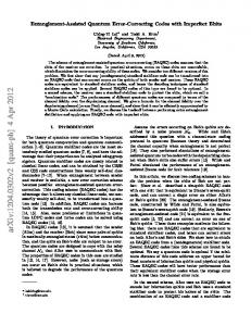
Figure-1: DRAM with Error Correction Kazéminéjad [5] proposed an improvement for the extended Hamming codes which proved that the codes are efficient in terms of area, speed and power as compared to the conventional extended Hamming Code based encoder/decoder circuits. However, this improvement comes with the penalty of one extra bit.
In case of circuits containing reconfigurable architectures, SEU can corrupt memory and logic nodes. Memory can be configuration or data memory. The corruption in the configuration memory can change the overall behaviour of the circuit and the corruption in the data memory can cause malfunctioning of the circuit and loss of precision.
In this paper, we propose, new single error correcting code based circuits (Encoder, Syndrome Generator and Decoder circuits comprising of Syndrome decoder and Errorcorrecting logic circuits), which not only reduce the complexity of both encoder and decoder circuits at all stages but also are more efficient in terms of area and power than all previously proposed circuits reported in the literature.
One of the most common approaches to avoid SEU is triple modular redundancy (TMR) with voter logic. The obvious disadvantage of this solution is that it triplicates the gate count which in turn triplicates area and power consumption.
2. PREVIOUS WORK
This area has been in research for decades to look for the fault tolerant architectures which can promise all the space related qualifications and which can shorten the design cycle.
In recent years, there has been an increase in demand for efficient and reliable digital data transmission and storage systems. A major concern is to control the errors so that reliable reproduction of the data can be obtained.
The manner in which reconfigurable logic can be used to make the satellite vehicle less susceptible to hardware and 2
Efficient codes are designed by keeping the ratio of parity bits to the data bits and making processing time involved in encoding and decoding the data stream as minimum as possible.
gives minimal encoder/decoder complexity and low power dissipation than all previously introduced techniques in the literature. The parity check matrix for the new (13,8) code is as follows:
Conventional (12,8) single error correction codes require 4 parity bits to correct single error in 8 data bits [4]. Kazéminéjad [5] introduced systematic (13,8) codes and proved that with the penalty of only one extra bit, the decoding complexity can be reduced to minimum. These codes were designed on the basis of the Hamming weight being equal to two [3]. The parity check matrix of Kazéminéjad’s systematic (13,8) code is as follows [5]:
1 1 1 1 0 0 0 0 1 0 0 0 0 1 0 0 0 1 1 0 0 0 1 0 0 0 B= 0 1 0 0 1 0 0 1 0 0 1 0 0 0 0 1 0 0 1 0 1 0 0 0 1 0 0 0 0 1 0 0 1 0 0 0 0 0 1 The parity check bits are given by
1 1 0 1 0 0 1 0 1 0 0 0 0 1 0 1 0 1 0 0 1 0 1 0 0 0 A= 0 1 1 0 0 1 0 0 0 0 1 0 0
P1 = M1 ⊕ M 2 ⊕ M 3 ⊕ M 4 P2 = M 1⊕ M 5 ⊕ M 6
P3 = M 2 ⊕ M 5 ⊕ M 8
0 0 0 1 1 1 0 0 0 0 0 1 0 0 0 0 0 0 0 1 1 0 0 0 0 1
P4 = M 3 ⊕ M 6 ⊕ M 8 P5 = M 4 ⊕ M 7
The parity bits mentioned above can correct any single error in 13-bit codeword (8 data + 5 parity).
Let Mi denote the data bits and Pi denote the parity check bits. Note that the data bits start from data bit-1 rather than zero. The parity check bits for (13,8) code are computed as follows [5]: P1 = M 1 ⊕ M 2 ⊕ M 4 ⊕ M 7 P2 = M 1 ⊕ M 3 ⊕ M 5 ⊕ M 8 P3 = M 2 ⊕ M 3 ⊕ M 6 P4 = M 4 ⊕ M 5 ⊕ M 6 P5 = M 7 ⊕ M 8
(6) (7) (8) (9) (10)
The Mni denotes the changed/corrupted data bits and Pni are the parity check bits calculated on the basis of corrupted data. All Pni bits are calculated through the same manner as explained in Equations [6-10]. The correction of any single data-bit can be explained as:
(1) (2) (3) (4) (5)
C 1 = Pn 1 ⊕ P 1 C 2 = Pn 2 ⊕ P 2
C 3 = Pn3 ⊕ P3
The above parity check bits can correct any single error in a 13-bit codeword.
C 4 = Pn 4 ⊕ P 4 C 5 = Pn5 ⊕ P5
3. PROPOSED ERROR CORRECTING CODE
(11) (12) (13) (14) (15)
Ci represent correction bits and M’i are the corrected data bits and are computed through following expressions.
The proposed new single error correcting code is constructed on the basis of Hamming weight. Hamming weight’s definition is taken as the number of ones in a column or row of the parity check matrix [5]. The code has been designed on the basis of maximum Hamming weight being equal to 2 in terms of columns but at least one column must have Hamming weight equal to 1, in such a way that any one row must have Hamming weight equal to 2.
M '1 = ( C 1 C 2 ) ⊕ Mn 1 M '2 = ( C 1C 3 ) ⊕ Mn 2
We have constructed new (13,8) error correcting codes based upon the above rule. This is further explained in the following section. As with Kazéminéjad’s codes, the proposed code also suffers from the penalty of one bit more than the conventional (12,8) Hamming error correcting code but
(16)
M '3 = ( C 1 C 4 ) ⊕ Mn 3
(17) (18)
M '4 = ( C 1C 5 ) ⊕ Mn 4
(19)
M '5 = ( C 2 C 3 ) ⊕ Mn 5
(20)
M '6 = ( C 2 C 4 ) ⊕ Mn 6
(21)
M '7 = C 1C 5 ⊕ Mn 7
(22)
M '8 = ( C 3 C 4 ) ⊕ Mn 8
(23)
The following table explains the error correction process of different data bits.
3
Table-1 Error Correction and Corresponding Correction Bits Correction Bits Corrected Data Bit (Used to correct the data) C1 & C2 C1 & C3 C1 & C4 C1 & C5 C2 & C3 C2 & C4 /C1 & C5 C3 & C4
Data bit-1 corrected Data bit-2 corrected Data bit-3 corrected Data bit-4 corrected Data bit-5 corrected Data bit-6 corrected Data bit-7 corrected Data bit-8 corrected
M’
D7 0
D6 1
D5 0
D4 1
Mnew
D7 0
D6 1
D5 0
D4 1
D3 0
D2 1
D1 0
M
D3 0
D2 1
D1 1
(30)
M '8 = (0.0) ⊕ 1 = 1
(31)
D8 1
D7 0
D8 1
D7 0
Porg
D6 1
D5 0
D4 1
D3 0
D2 1
D1 0
D6 1
D5 0
D4 1
D3 0
D2 1
D1 0
Porg5 1
Porg4 0
Porg3 0
Porg2 1
Porg1 0
Let’s assume that the Porg1 has been corrupted by SEU. Pnewi represents the parity check bits after SEU
Pnew
The correction bits are calculated by using these parity check bits (Porgi and Pcali) in Equations [11-15] Pcal1 = 1 Pcal2 = 0 Pcal3 = 0 Pcal4 = 0 Pcal5 = 1
M '7 = 1.0 ⊕ 0 = 0
Equations [8-12] give parity check bits (Porgi) for the data (M). These parity bits are stored in memory along with the data bits and are shown below.
Equations [6-10] give Parity Check bits for the original data (Morg) and for corrupted data (Mnew). Porgi represents the parity check bits for the original data (Morg) and Pcali represents the parity check bits, calculated for the corrupted data (Mnew)
Porg1 = 0 Porg2 = 1 Porg3 = 0 Porg4 = 0 Porg5 = 1
(29)
Let’s assume that SEU corrupts one of the parity bits stored in the memory. Let’s take M as Data and is shown below
Note that the least significant bit is referenced as D1 rather than D0. And now assume that the first bit (D1) is changed due to single event upset (SEU) from 0 to 1, Mnew represents the data after single event upset: D8 1
M '6 = (1.0) ⊕ 1 = 1
Case Example-2: An Error in Parity Bits
Let’s assume that Morg is original Data as shown below: D8 1
(28)
Note that D1 is corrected while all other bits are unchanged.
Case Example-1: An Error in Data Bits
Morg
M '5 = (1.0) ⊕ 0 = 0
Pnew 5 1
Pnew 4 0
Pnew 3 0
Pnew 2 1
Pnew1 1
Pcali are calculated through Equations [6-10] for the data stored in the memory. It is quite clear that the Porgi and Pcali will be same as the data has not been changed.
C1 = 1 C2 = 1 C3 = 0 C4 = 0 C5 = 0
The correction bits are calculated by using these parity check bits (Pcali and Pnewi) in Equations [11-15] Pcal1 = 0 Pcal2 = 1 Pcal3 = 0 Pcal4 = 0 Pcal5 = 1
The correction bits (Ci) along with the corrupted data (Mnew) due to SEU is used in Equations [16-23] to correct the single bit faults. In this particular example D1 (least significant bit) is corrected as follows
M '1 = (1 . 1) ⊕ 1 = 0
(24)
M '2 = (1.0) ⊕ 1 = 1
(25)
M '3 = (1.0) ⊕ 0 = 0
(26)
M '4 = (1.0) ⊕ 1 = 1
(27)
Pnew1 = 1 Pnew2 = 1 Pnew3 = 0 Pnew4 = 0 Pnew5 = 1
C1 = 1 C2 = 0 C3 = 0 C4 = 0 C5 = 0
The correction bits (Ci) along with the data (M) is used in Equations [16-23] to correct the single bit faults. In this particular example data is not corrupted and the only one of the parity check is corrupted. M’i represents the corrected data and it is same as M.
M '1 = (1 . 0 ) ⊕ 0 = 0
4
(32)
M’
D8 1
M '2 = (1.0) ⊕ 1 = 1
(33)
M '3 = (1.0) ⊕ 0 = 0
(34)
M '4 = (1.0) ⊕ 1 = 1
(35)
M '5 = (0.0) ⊕ 0 = 0
(36)
M '6 = (0.0) ⊕ 1 = 1
(37)
M '7 = 1.0 ⊕ 0 = 0
(38)
M '8 = (0.0) ⊕ 1 = 1
(39)
D7 0
D6 1
D5 0
D4 1
D3 0
D2 1
D1 0
Note that SEU in parity check bits does not disturb the data bits and proposed error correcting-code work in both scenarios i-e Single Event Upset in data and SEU in case of parity check bits. Figure-2a: Proposed (13,8) code based encoder circuitry.
The code introduced in this paper can correct any single data bit among 8 data bits. Normally, the error correcting codes which are quite efficient for the large memories are not that efficient in terms of area and power. We have devised new error codes for small memories like 4bit wide memories on the basis of the same principle. The results prove that these codes are even better for small memories than previous approaches.
For comparison, encoder based on Kazéminéjad’s [5] codes is presented in Figure-2b.
4. E.C.C. ENCODER An encoder converts the incoming data/message into a codeword. The codeword is then stored in memory in possible presence of high-energy ion or radiation that may corrupt the data/message. The decoder attempts to convert the codeword back to original data/message. Each encoder/decoder can handle a set of possible error conditions. With some schemes, the decoder can only detect an error and outputs an “error”. With other schemes, the decoder can not only detect an error but also can correct the error to reproduce the original data/message.
Figure-2b: Kazéminéjad’s (13,8) [5] code based encoder circuitry.
The encoder for the new code is shown in the Figure-2a. A two input XOR gate (XOR2) is used for the implementation of the encoder circuitry.
5
Figure-3a: Proposed (13,8) code based syndrome generator Note that Ci check-bits are used by decoder’s error correcting logic to correct any single error in the codeword. It is quite evident that proposed code gives simple solution for the syndrome generator’s circuitry than all the previous implementations. Implementation of syndrome generator based upon Kazéminéjad’s code [5] is represented in Figure3b.
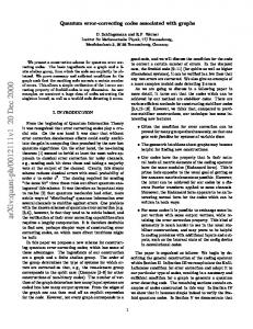
Figure-2c: Power comparison of different encoders The Figure-2c shows the power comparison of encoder circuits based upon different error correction codes. The proposed error correction code takes approximately 85% power of the Hamming code based encoder. Hence, a saving of approximately 22% is achieved by using our proposed code-based encoder. As compared to Kazéminéjad’s [5], our code-centric encoder is approximately 9% efficient in terms of power consumption.
5. E.C.C. DECODER A decoder consists of a syndrome generator, syndrome decoder and error correcting logic [5]. The syndrome generator computes the parity check bits based upon the data received and compares with the received parity check bits. Based upon this comparison the corrector logic corrects any single error that occurs in the 13-bit codeword. Figure-3a represents the implementation of the syndrome generator based upon the proposed new (13,8) code while Figure-3b represents the Kazéminéjad’s [5] codes based syndrome generator.
Figure-3b: Kazéminéjad’s (13,8) [5] code based syndrome generator circuitry. This improvement makes this code-centric circuits most suitable for the applications which are power and area critical. The decoder’s error correcting section based upon the proposed new (13,8) code [5] is presented in Figure-4b. Note that the M’i represents the corrected data, Mi denotes data stored in memory (which may be corrupted by SEU) and Ci represents the correction bits in the Figure-4[a, b].
6
6. OVERALL COMPLEXITY COMPARISON For overall comparison, we have implemented circuits using 0.18µm technology and the results (in terms of area) are shown in the figure-5. The area consumed is a good measure for the complexity and it can be seen that the overall complexity of circuits based upon the proposed code has been reduced by 21% as compared to the Hamming code based implementations. As compared to Kazéminéjad’s [5] approach, our proposed code based circuits (encoder and decoder) use 10% to 11% less area which prove that the proposed code based circuits are less complex. This is shown in Figure-6. The area saving is mainly due to the fact that encoder is using less number of gates as compare to the Hamming code and other implementations. This is explained in Table-1 and Table-2
A r e a (u m 2 )
300 Figure-4a: Kazéminéjad’s (13,8) [5] code based syndrome decoder & correcting circuitry.
250 200 150 100 50 0
Proposed
Kazéminéjad’s (13,8) [5]
Hamming
Figure-5 Area comparison of encoder implementations based on different error correction codes Table-1: Comparison of different Encoders
Circuit’s complexity and power dissipation are measured in terms of total gate count. As explained before, harware realization is carried out by using two input XOR gates. Table-1 provides a comparison between previous implementations of the encoder and that of ours. It is evident from the results that the implementation of the encoder based upon our technique, is better in terms of complexity and power dissipation than the previous techniques. Note that, new proposed encoder’s complexity and power dissipation are reduced by one XOR gate compared to the previously improved technique.
Figure-4: Proposed (13,8) code based syndrome decoder and correcting circuits. The decoder’s error correcting circuitry for the proposed (13,8) code uses one extra inverter than the Kazéminéjad’s systematic (13,8) code [5] based circuitry however, the overall complexity and power dissipation of the decoder (shown in Figure-4) is reduced comprehensively (explained in next section).
7
Table-1: Comparison of different Encoders
Complexity
(12,8) Hamming [4] 13 XOR2
Delay
3 XOR2
ENCODER
(13,8)
Kazéminéjad’s
PROPOSED
2 XOR2
10 XOR2 (REDUCED) 2 XOR2
[5] 11 XOR2
based circuits but also better than recent work done in this area such as Kazéminéjad’s systematic code [5]. The added advantage of this technique overcomes the limitations of the currently employed techniques and extends the use of proposed code based circuits to other applications such as those which are space related.
REFERENCES
Table-2 presents the comparison of two syndrome generators based upon complexity and power dissipation. Note that the complexity and power dissipation is reduced by one, two input XOR (XOR2) gate than previous implementation.
[1] Dick, C., ‘FPGA: The High-End Alternative For DSP Applications’, DSP Engineering, Spring 2000. [2] White, S. A., ‘Applications of Distributed Arithmetic to Digital Signal Processing: A Tutorial Review’, IEEE Acoustics, Speech and Signal Processing Magazine, pp. 419, 1989.
Table-2: Comparisons of syndrome generators. (13,8) SYNDROME GENERATOR Complexity
Kazéminéjad’s
PROPOSED (13,8)
16 XOR2
15 XOR2 (REDUCED) 15 XOR2 (REDUCED) 3 XOR2
A r e a (u m 2 )
Power Dissipation Delay
100% 90% 80% 70% 60% 50% 40% 30% 20% 10% 0%
[3] Mazumder, P.: ‘Design of a Fault-Tolerant ThreeDimensional Systematic random-access Memory with onchip Error-Correcting Circuit’, IEEE Trans. Comput., 1993, 42, (12), pp. 1453-1468
[5]
16 XOR2 3 XOR2
Area Saving
[4] Boyyarinov, I., Farrell, P., Markarian, G., and Honary, B.: ‘Random Double-Bit Error Correcting Generalized Array Codes’, Electron Lett., 1997, 33, (5), pp. 382-383 [5] Kazéeminejad, A., ‘Fast, Minimal Decoding Complexity, Systematic (13,8) Single-Error-Correcting Codes for onchip DRAM Applications’, Electron Lett., 2001.
Saving
[6] Kazéeminejad, A. and B. Eric, ‘Fast, Minimal Decoding Complexity, System Level, Binary Systematic (41,32) Single-Error-Correcting Codes for on-chip DRAM Applications’, Proceeding 2001 IEEE international symposium on defect and fault tolerance in VLSI.
BIOGRAPHY Proposed
Kazéminéjad’s (13,8) [5]
Adrian Stoica is a Principal Member of Technical Staff in the Biologically Inspired Technology and Systems (BITS) Group in the Avionics Equipment Section at the Jet Propulsion Laboratory, California Institute of Technology. He obtained his MSEE degree from the Technical University of Iasi, Romania, ranking the first among the graduates in Applied Electronics Specialty. He received his Ph.D. in EECS from Victoria University of Technology in Melbourne, Australia, with a thesis titled “Motion learning by robot apprentices – a fuzzy neural approach”, which was the earliest work on humanoid robot motor skill learning by imitation. Since early 1986 his engineering and research work revolved around adaptive and learning techniques for autonomous intelligent systems. He joined JPL in 1996
Hamming
Figure-6 Overall comparison of encoder and decoder process based on different error correction codes in term of area.
7. CONCLUSION We have presented a new high performance and low power single error correcting code and its associated circuits. We have shown that the proposed code and code centric circuits are not only better than the conventional Hamming code
8
where he has been working along two main themes: adaptive hardware for space autonomous systems, including evolvable/reconfigurable hardware, adaptive/learning hardware and sensor fusion hardware, and next-generation robots, focusing on rover intelligence and robot sensorymotor control. His current projects in reconfigurable and evolvable hardware address analog/digital fieldprogrammable reconfigurable computing, automated hardware/software co-design and novel search/optimization techniques. Dr. Stoica initiated, and has chaired/co-chaired yearly since 1999, the NASA/DOD Conference in Evolvable Hardware, the main conference in the field of evolvable hardware as judged by number of attendants and references to published papers. He was Conference keynote speaker at ISMVL, ANNIE, gave tutorials at GECCO 2001 and CEC2003, and taught the first short course on Evolvable Hardware in the summer of 2003 at UCLA Extension. He has published over 100 papers in the areas of evolvable hardware, reconfigurable computing, fuzzy logic, neural networks, robot learning and is serving in the editorial board of several journals. He has received the 1999 JPL Lew Allen Award for Excellence (highest JPL award for excellence in research) and the Tudor Tanasescu Prize of the Romanian Academy in 2001.
Prof. Tughrul Arslan received the B.Eng. and Ph.D. degrees from the University of Hull, Hull, U.K., in 1989 and 1993, respectively. He is currently a Professor in the Department of Electronics and Electrical Engineering at the University of Edinburgh, Scotland, U.K., where he leads the digital VLSI activity. He is also a Lecturer at the Institute for System-Level-Integration, Livingston, Scotland, U.K. His research interests include low-power VLSI and systemon-chip design, high-performance DSP architectures, and evolutionary algorithms and their application to circuit design Sajid Baloch received his BSc Engineering degree from University of Engineering and Technology, Lahore, Pakistan. He did his MSc from Institute for System Level Integration, Livingston, Scotland, UK in 2003 and won runners-up prize for the best student of the institute. He is currently doing his PhD from Edinburgh University, Scotland, UK. His research interests are Fault tolerant systems for space application and SEU hardened reconfigurable architectures.
9