arXiv:0708.3022v1 [cs.CR] 22 Aug 2007
EFFICIENT FPGA-BASED MULTIPLIERS FOR F397 AND F36·97 Jamshid Shokrollahi ∗
Elisa Gorla †
Christoph Puttmann∗
B-IT University of Bonn Germany
[email protected]
Department of Mathematics University of Z¨urich Switzerland
[email protected]
Heinz Nixdorf Institute University of Paderborn Germany
[email protected]
ABSTRACT In this work we present a new structure for multiplication in finite fields. This structure is based on a digit-level LFSR (Linear Feedback Shift Register) multiplier in which the area of digit-multipliers are reduced using the Karatsuba method. We compare our results with the other works of the literature for F397 . We also propose new formulas for multiplication in F36·97 . These new formulas reduce the number of F397 multiplications from 18 to 15. The finite fields F397 and F36·97 are important fields for pairing based cryptography. Keywords: finite field multiplication, FPGA, pairing based cryptography. 1. INTRODUCTION Efficient multiplication in finite fields is a central task in the implementation of most public key cryptosystems. A great amount of work has been devoted to this topic (see [1] or [2] for a comprehensive list). The two types of finite fields which are mostly used in cryptographic standards are binary finite fields of type F2m and prime fields of type Fp , where p is a prime (cf. [3]). Efforts to efficiently fit finite field arithmetic into commercial processors resulted into applications of medium characteristic finite fields like those reported in [4] and [5]. Medium characteristic finite fields are fields of type Fpm , where p is a prime slightly smaller than the word size of the processor, and has a special form that simplifies the modular reduction. Mersenne prime numbers constitute an example of primes which are used in this context. The security parameter is given by the length of the binary representations of the field elements, and the extension degree m is selected appropriately. Due to security considerations, the extension degree for fields of characteristic 2 or medium characteristic is usually chosen to be prime. With the introduction of the method of Duursma and Lee for the computation of the Tate pairing (cf. [6]), fields of ∗ Partially funded by the German Research Foundation (DFG) under project RU 477/8 † Partially funded by the Swiss National Science Foundation under grant no. 107887
type F3m for m prime have attracted special attention. Computing the Tate pairing on elliptic curves defined over F3m requires computations both in F3m and in F36m . In [7] calculations are implemented using the tower of extensions F3m ⊂ F32m ⊂ F36m and the inherent parallelism of multiplication in extension fields is used to accelerate the operations. Hardware designs and especially FPGA-based ones are suitable platforms for parallel implementation of algorithms. In that work multiplications in the first and the second field extensions are computed via 3 and 6 multiplications in the ground fields, respectively, requiring 18 multiplications in F397 . In our current work, which is mostly based on [7], on the one hand, we use asymptotically fast methods to improve the performance of multiplication in F397 , and on the other hand, we propose new multiplication formulas to speedup multiplication in F36·97 . Using the new formulas, multiplication in F36·97 is done with only 15 multiplications instead of 18. We use the same extension tower, using 3 multiplications in F397 to multiply elements in F32·97 , but only 5 multiplications in F32·97 for F36·97 . Our proposed method has a slightly increased number of additions in comparison to the Karatsuba method. Notice however that a multiplication in F397 requires many more resources than an addition, therefore the overall resource consumption will be reduced. The details of our method to generate the new formulas have been omitted to limit the complexity and diversity of materials in this paper, and have been submitted as another paper for CHES 2007. A consistent amount of work has been done on hardwarebased multiplication in finite fields, especially those of characteristic 3. The authors of [8] propose a least significant digit-element (LSDE) multiplier for F3m . This multiplier divides the input polynomials into digits of length D. Whereas the digits of one input polynomial are processed in parallel, the digits of the other input polynomial are handled serially. Then the result is reduced modulo the irreducible polynomial. The same structure has also been used in [7] for multiplication in F397 . Our multiplier, on the other hand, is based
on the digit-serial implementation of LFSR (Linear Feedback Shift Register) multiplier which is widely used in the literature (see [9] or [10]), and performs the modular reduction during the multiplication. The first contribution of our current work is the application of the Karatsuba multiplier inside the digit-multipliers, which results in smaller area for these multipliers. Our results demonstrate the efficiency of this design compared to other works. The second contribution is the application of a method using only 5 multiplications in F32·97 for multiplication in F36·97 . This results in an area-saving of almost 17% compared to the Karatsuba method which is used in [7]. Our work is organized as follows. Section 2 is devoted to the general structure of our multiplier for F397 . In Section 3 we describe some improvements on the traditional LFSR multiplier and compare our results with other works from the literature. In Section 4 the new formulas for F36·97 together with suggestions for a new multiplier are presented, and Section 5 concludes the paper.
2. MULTIPLICATION IN F397 The finite field F397 can be represented as a vector space over F3 . In this representation, elements of F397 are vectors of length 97 over F3 . Addition of elements is computed by adding corresponding vectors. Multiplication is more complicated, and depends on the selected basis for F397 . There are two popular bases which are used often in the literature, namely polynomial and normal bases. A polynomial basis is generally more suitable for multiplication, hence we choose this basis in our work. In the polynomial basis, elements of F397 are represented as polynomials of degree at most 96 over F3 . Two elements are added by adding of the corresponding polynomials. Multiplication is based on polynomial multiplication followed by reduction modulo the irreducible polynomial, which generates the polynomial basis. In our case the irreducible polynomial, which we denote by f (x), is x97 + x16 + 2.
(1)
In the next sections we show the details of polynomial arithmetic in our designs.
2.1. Arithmetic in F3 The element a ∈ F3 is represented using the vector (a1 , a0 ) of two bits such that the elements 0, 1, and 2 are (0, 0), (0, 1), (1, 0), respectively. In this representation the operations addition, multiplication, and negation (multiplication by 2) are done, as shown in [11], using Equations 2, 3, and
b(x)
B0
B1
a(x)
...
Bm-1
A0
A1
...
Am-1
M
M
...
M
Overlap Circuit
c0
c1
...
cn-1
Feedback Circuit
Fig. 1. Structure of a digit-level LFSR multiplier
4, respectively. (a1 , a0 ) + (b1 , b0 ) = ((a0 ∨ b0 ) ⊕ t, (a1 ∨ b1 ) ⊕ t), (2) where t = (a0 ∨ b1 ) ⊕ (a1 ∨ b0 ) (a1 , a0 ) · (b1 , b0 ) = ((a1 ∧ b0 ) ∨ (a0 ∧ b1 ),
(3)
(a0 ∧ b0 ) ∨ (a1 ∧ b1 ), − (a1 , a0 ) = (a0 , a1 ).
(4)
The implementation of Equations 2 and 3 is done using 2 LUTs in the FPGA, whereas (4) is only a permutation of bits.
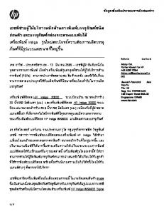
2.2. Structure of the multiplier for F397 The structure of a digit-level LFSR multiplier is shown in Figure 1. In this figure the two input polynomials a(x), and b(x) are loaded into registers A and B, respectively, and divided into digits of length D. In each clock cycle the most significant digit of B is multiplied by the words of A, through digit-multipliers specified by M, and added to the content of the register in the feedback circuit. Inputs to the digit multipliers are two polynomials of degree D − 1 in x. The product is a polynomial of degree 2(D − 1). Powers xD to x2(D−1) of each multiplier must be added to the powers x0 to xD−2 of the next multiplier. This is done by the overlap circuit. In each clock cycle the register B and LFSR are shifted by D bits to the right. Shifting LFSR to right is equivalent to multiplication by xD which generates the powers x97 to x96+D . These powers are reduced modulo f (x) of (1) using the feedback circuit. The name Linear Feedback Shift Register descends from these feedback structures. For more information about the digit-level LFSR multiplier and its costs for classical methods see [10]. In the next section we discuss our improvements to the traditional LFSR multiplier.
3. THE KARATSUBA METHOD In this section we use asymptotically fast methods to reduce the size of digit-multipliers. We use a similar approach to [12] and combine the classical and the Karatsuba methods to build small digit-multipliers. Two linear polynomials a1 x + a0 and b1 x + b0 are multiplied classically using the formula a1 b1 x2 + (a1 b0 + a0 b1 )x + a0 b0
Table 1. Timing and area costs of digit-level LFSR multipliers in F397 for different values of digit-size D D
Multiplication
# of slices
1 2 4 7 14
− C2 C4 KC4 KKC4
327 800 1716 2954 4006
Maximum frequency (MHz) 300 174 125 111 72
# of clock cycles = ⌈97/D⌉ 97 49 25 14 7
(5)
with 4 multiplications and 1 addition. The same product can also be computed via a1 b1 x2 + ((a1 + a0 )(b1 + b0 ) − a1 b1 − a0 b0 )x + a0 b0 . (6) The new formula is called the Karatsuba method (see [13]). It requires 7 operations instead of 5, but only 3 multiplications, and uses fewer resources when the coefficients a0 , a1 , b0 , b1 are replaced by polynomials. The classical method for multiplication of two polynomials of degree n − 1 requires O(n2 ) operations. Recursive application of the Karatsuba method reduces the cost of a multiplication to O(n1.59 ) operations. We represent the classical multiplication of two polynomials of degree n − 1 by Cn and the method of (6) by K. The methods Cn for n ∈ N, and K constitute a set of polynomial multiplication methods. We call this set T. Using the elements of T we define the set of recursive multiplication methods T∗ which contains the elements of T and all recursive combinations of elements of T∗ . The recursive combination of the two methods M and N , for polynomials of lengths m and n, respectively, is the multiplication method MN for polynomials of length mn. Let a(x) = amn−1 xmn−1 + · · · + a0 , and b(x) = bmn−1 xmn−1 + · · · + b0 be given polynomials. In order to apply MN , we write these polynomials as a(x) = Am−1 X m−1 + · · · + A0 , and
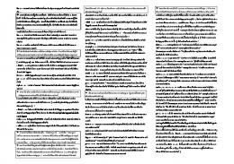
m/D is as small as possible. Our values for D are selected using this criteria and hence differ from other standard values like multiples of 4 in other works (see [8] and [7]). The string in the second column shows the recursive combination of the Karatsuba and classical methods which is applied. It is important to notice that the method KC2 , which we used for polynomials of degree 6, applies to polynomials of length 7. Therefore, we add a zero in front of the polynomial and then remove all the gates containing an operation with the coefficients which are known to be zero. Hence this multiplier requires fewer resources than a complete KC2 . This point distinguishes our approach from that in [12]. In the third, fourth, and fifth columns are the number of slices, maximum working frequency of the multiplier, and the required clock cycles for our designs. The results of comparing our results with those in [7] are shown in Figure 2. Different digit-levels result in different circuits, which we compare with respect to both time and area. Area is the number of slices, whereas time is the product of clock cycles and minimum period. Both designs are on the same technology, but the speed grade of the FPGA in [7] is not available. As it is shown, our designs have better area-time performance. These improvements result, on the one hand, by using asymptotically faster methods, and on the other hand, by integrating the modular reduction stage into the LFSR. When a small digit-serial multiplier is used even the small size of a modular reduction must be taken into account.
b(x) = Bm−1 X m−1 + · · · + B0 , where X = xn and A0 , · · · Am−1 , B0 , · · · Bm−1 are polynomials of degree n − 1. If the polynomials Ai and Bi were coefficients, the two polynomials a(x) and b(x) would be multiplied using M. The product using the method MN consists of several multiplications of the polynomials Ai and Bi , which are performed using N . We implement the digitmultipliers using the elements of T∗ to reduce their size. Our approach is similar to [12]. In Table 1 we show the results of implementing F397 multipliers on a XC2VP20-6FF896 FPGA. In this table the first column is the digit-size D. In a digit-level multiplier with digit-size D, inputs are preceded by enough zeros so that their length becomes a multiple of D. Hence it is natural to choose a value of D such that the difference ⌈m/D⌉ −
4. MULTIPLICATION IN F36·97 Multiplication in F36·97 is done in the same way as in [7], as a tower of extensions of degrees 2 and 3, i.e. F397 F32·97 F36·97
∼ = ∼ = ∼ =
F3 /(x97 + x16 + 2) F397 /(y 2 + 1) F32·97 /(z 3 − z − 1).
The elements of F32·97 are polynomials of degree 1 in s over F397 , for s a root of y 2 + 1 in F32·97 . The polynomials are multiplied by applying (6) and then reduced modulo s2 + 1. The elements of F36·97 are polynomials of degree 3 in r, a root of z 3 − z − 1 in F36·97 . They are multiplied using the
Multipliers from [7] Our designs
s
−1
−s
s
−1
input stage
−s
from memory
750
500
accumulator
250
accumulator
F397 -multiplier
0
−s
0
1000
2000
3000
4000
Area [Number of Slices]
Fig. 2. Time vs. area comparisons of our multipliers with those in [7]
s
−1
output stage
Time [ns] (Number of clock cycles × Minimum clock-period)
from memory
accumulator to memory
from memory
formulas (7) and then reduced modulo r3 − r − 1. (a0 + a1 r + a2 r2 )(b0 + b1 r + b2 r2 ) = c0 + c1 r + c2 r2 + c3 r3 + c4 r4 , where P0 = (a0 + a1 + a2 )(b0 + b1 + b2 ) P1 = (a0 + sa1 − a2 )(b0 + sb1 − b2 ) P2 = (a0 − a1 + a2 )(b0 − b1 + b2 ) P3 = (a0 − sa1 − a2 )(b0 − sb1 − b2 ) P4 = a2 b2 , and c0 = P0 + P1 + P2 + P3 − P4 c1 = P0 − sP1 − P2 + sP3 c2 = P0 − P1 + P2 − P3 c3 = P0 + sP1 − P2 − sP3 c4 = P4 ,
Fig. 3. The proposed structure block for implementing the formulas of Appendix A
(7)
Combining (6), (7) we have the following theorem. Theorem 1 Let α, β ∈ F36·97 be given as: α =a0 + a1 s + a2 r + a3 rs + a4 r2 + a5 r2 s β =b0 + b1 s + b2 r + b3 rs + b4 r2 + b5 r2 s. Let further their product γ = αβ ∈ F36·97 be γ = c0 + c1 s + c2 r + c3 rs + c4 r2 + c5 r2 s. Then the coefficients c0 · · · c5 of the product can be computed using only 15 multiplications in F397 . Closed-form formulas for this multiplication are shown in Appendix A. Scalar multiplications are particularly simple using these formulas. Scalar multiplications are multiplications by −1, s, and −s. Negation of coefficients and
consequently of polynomials is only a permutation of bits, as seen in Section 2. Indeed multiplication of an element in F32·97 by s is a permutation, too. Let α = a1 s+ a0 ∈ F32·97 , then sα = a1 s2 + a0 s
mod s2 + 1 = a0 s − a1 .
All of the F397 -multiplications can be done in parallel. This property allows designers to implement as many of these multipliers as possible, according to their time-area constraints. On the other hand, these multipliers are used for other computations such as point addition and doubling on elliptic curves for pairing-based cryptography. Reading and writing intermediate values into register files in such applications is time-consuming. To solve this problem we propose a new multiplier which is shown in Figure 3. The new multiplier consists of three pipeline stages, namely, input, multiplication, and output. During the time of each multiplication in F397 , the input stage loads the coefficients ai and bi from memory for the next multiplication, and computes the linear combinations in (8) to compute Pi s. In this time the output stage adds the last computed product Pi to memory variables according to (9). In this structure the hatched multiplexers can select either one of their inputs or the sum of the inputs. In this way all possible multiples of input polynomials can be selected and added to the accumulators.
5. CONCLUSION In this paper we proposed a new structure for multiplication in F397 . This structure is based on digit-level LFSR multipliers, where the area of digit-multipliers are reduced using the Karatsuba method. Another advantage of this approach is performing the modular reduction during the multiplication. Our synthesis results showed the performance improvement compared to other designs in the literature. We have also presented new formulas for multiplication in F36·97 using only 15 multiplications in F397 . When the Karatsuba method is applied 18 multiplications are required. Furthermore, we have introduced a feasible hardware structure for realizing our proposed formulas. Our formulas are for the case that F36·97 is constructed from F32·97 using the irreducible polynomial z 3 − z − 1. In case that the finite field is constructed using z 3 − z + 1, the formulas require slight modifications. 6. REFERENCES [1] D. E. Knuth, The Art of Computer Programming, vol. 2, Seminumerical Algorithms, 3rd ed. Reading MA: AddisonWesley, 1998, first edition 1969. [2] J. von zur Gathen and J. Gerhard, Modern Computer Algebra, 2nd ed. Cambridge, UK: Cambridge University Press, 2003, first edition 1999. [3] Digital Signature Standard (DSS), U.S. Department of Commerce / National Institute of Standards and Technology, January 2000, federal Information Processings Standards Publication 186-2. [Online]. Available: http://csrc.nist.gov/publications/fips/fips186-2/fips186-2.pdf [4] D. V. Bailey and C. Paar, “Optimal extension fields for fast arithmetic in public-key algorithms,” in Advances in Cryptology: Proceedings of CRYPTO ’98, Santa Barbara CA, ser. Lecture Notes in Computer Science, H. Krawczyk, Ed., no. 1462. Springer-Verlag, 1998, pp. 472–485. [5] R. M. Avanzi and P. Mih˘ailescu, “Generic efficient arithmetic algorithms for PAFFs (processor adequate finite fields) and related algebraic structures (extended abstract),” in Selected Areas in Cryptography (SAC 2003). Springer-Verlag, 2003, pp. 320–334. [6] I. Duursma and H. Lee, “Tate-pairing implementations for tripartite key agreement.” [Online]. Available: citeseer.ist.psu.edu/duursma03tatepairing.html [7] T. Kerins, W. P. Marnane, E. M. Popovici, and P. S. L. M. Barreto, “Efficient hardware for the tate pairing calculation in characteristic three,” in Cryptographic Hardware and Embedded Systems, CHES2005, ser. Lecture Notes in Computer Science, J. R. Rao and B. Sunar, Eds., vol. 3659. SpringerVerlag, 2005, pp. 412–426. [8] G. Bertoni, J. Guajardo, S. Kumar, G. Orlando, C. Paar, and T. Wollinger, “Efficient GF (pm ) arithmetic architectures for cryptographic applications,” in Topics in cryptology, CTRSA 2003: the Cryptographers’ Track at the RSA Conference
2003, San Francisco, CA, USA, April 13–17, 2003: Proceedings, ser. Lecture Notes in Computer Science, M. Joye, Ed., vol. 2612. Springer-Verlag, 2003, pp. 158–175. [9] R. J. McEliece, Finite Fields for Computer Scientists and Engineers. Kluwer Academic Publishers, 1987.
[10] J. Shokrollahi, “Efficient implementation of elliptic curve cryptography on fpgas,” Ph.D. dissertation, Bonn University, Bonn, December 2006. [Online]. Available: http://hss.ulb.uni-bonn.de/diss online/math nat fak/2007/shokrollahi jamshid/i [11] R. Granger, D. Page, and M. Stam, “Hardware and software normal basis arithmetic for pairing-based cryptogaphy in characteristic three,” IEEE Transactions on Computers, vol. 54, no. 7, pp. 852–860, 2005. [Online]. Available: http:// [12] J. von zur Gathen and J. Shokrollahi, “Fast arithmetic for polynomials over F2 in hardware,” in IEEE Information Theory Workshop (2006). Punta del Este, Uruguay: IEEE, March 2006, pp. 107–111. [13] A. Karatsuba and Y. Ofman, “Multiplication of multidigit numbers on automata,” Soviet Physics–Doklady, vol. 7, no. 7, pp. 595–596, January 1963, translated from Doklady Akademii Nauk SSSR, Vol. 145, No. 2, pp. 293–294, July, 1962.
A. MULTIPLICATION FORMULAS FOR F36·97
Let α, β ∈ F36·97 be given as:
α =a0 + a1 s + a2 r + a3 rs + a4 r 2 + a5 r 2 s, β =b0 + b1 s + b2 r + b3 rs + b4 r 2 + b5 r 2 s,
where a0 , · · · , b5 ∈ F397 and s ∈ F32·97 , r ∈ F36·97 are roots of y 2 + 1 and z 3 − z − 1, respectively. Let their product γ = αβ ∈ F36·97 be
γ = c0 + c1 s + c2 r + c3 rs + c4 r 2 + c5 r 2 s.
Then the coefficients c0 · · · c5 ∈ F397 of the product can be computed using the following formulas.
P0 = P1 = P2 = P3 = P4 = P5 = P6 = P7 = P8 = P9 = P10 = P11 P12 P13 P14
= = = =
(a0 + a2 + a4 )(b0 + b2 + b4) (a0 + a1 + a2 + a3 + a4 + a5 ) (b0 + b1 + b2 + b3 + b4 + b5 ) (a1 + a3 + a5 )(b1 + b3 + b5 ) (a0 + sa2 − a4 )(b0 + sb2 − b4 ) (a0 + a1 + sa2 + sa3 − a4 − a5 ) (b0 + b1 + sb2 + sb3 − b4 − b5 ) (a1 + sa3 − a5 )(b1 + sb3 − b5 ) (a0 − a2 + a4 )(b0 − b2 + b4 ) (a0 + a1 − a2 − a3 + a4 + a5 ) (b0 + b1 − b2 − b3 + b4 + b5 ) (a1 − a3 + a5 )(b1 − b3 + b5 ) (a0 − sa2 − a4 )(b0 − sb2 − b4 ) (a0 + a1 − sa2 − sa3 − a4 − a5 ) (b0 + b1 − sb2 − sb3 − b4 − b5 ) (a1 − sa3 − a5 )(b1 − sb3 − b5 ) a 4 b4 (a4 + a5 )(b4 + b5 ) a 5 b5
c0 = c1 =
c2 = c3 = (8)
c4 = c5 =
−P0 + P2 + (s + 1)P3 − (s + 1)P5 − (s − 1)P9 + (s − 1)P11 − P12 + P14 P0 − P1 + P2 − (s + 1)P3 + (s + 1)P4 − (s + 1)P5 + (s − 1)P9 − (s − 1)P10 + (s − 1)P11 − P12 − P13 + P14 −P0 + P2 + P6 − P8 + P12 − P14 P0 − P1 + P2 − P6 + P7 − P8 − P12 +P13 − P14 P0 − P2 − P3 + P5 + P6 − P8 − P9 + P11 + P12 − P14 P0 + P1 − P2 + P3 − P4 + P5 − P6 + P7 − P8 + P9 − P10 + P11 − P12 + P13 − P14
(9)