Efficient Interference Mitigating Strategies for Two-Way Relay Channels Agisilaos Papadogiannis∗ , Alister G. Burr∗ , and Meixia Tao† ∗ Communications † Department
Research Group, Department of Electronics, University of York, York, YO10 5DD, U.K. of Electronic Engineering, Shanghai Jiao Tong University, Shanghai 200240, China.
[email protected],
[email protected],
[email protected]
Abstract—Dual-hop hierarchical wireless networks have the potential to provide the needed capacity to a large number of mobile stations (MSs). According to this system architecture, the MSs are served by a dense network of fixed relay nodes (RNs) fed by a small number of large hub base stations (HBSs). In such deployment, high spectral efficiencies can be achieved if the RNs act as two-way relays; however this gives rise to co-channel interference (CCI) which needs to be mitigated. In order to gain insights on the impact of CCI to this scenario we consider an HBS with two highly directional antennas communicating with two MSs via two interfering two-way RNs. We investigate the average maximum sum-rate of a cooperative strategy based on Decodeand-Forward (DF) with network coding and a strategy based on Amplify-and-Forward (AF) with Network MIMO. Furthermore we devise some cooperative protocols that utilise two, three or four time slots. It is shown that the 2-slot schemes perform generally better and that the DF strategy achieves superior performance when CCI is low while AF with Network MIMO is superior when CCI is high. Index Terms—Two-way relaying, hierarchical networks, decode-and-forward (DF), amplify-and-forward (AF).
I. I NTRODUCTION The use of relay nodes (RNs) in wireless networks has been recognized as a very promising avenue towards future wireless communications [1]. RN-enabled communications are seen as cost-effective means to improve connectivity, transmission reliability and quality-of-service without requiring a large number of antenna elements per network node [1], [2]. RNs can be inexpensive fixed wireless nodes or even user terminals that relay signals indended for other users [3], [4]. Recently it has been identified that RN-enabled networks apart from achieving the aforementioned gains, they can also greatly increase the achievable capacity density of the network, measured in bits/sec/km2 [5], [6]. A promising hierarchical architecture for future wireless systems entails that mobile stations (MSs) are served in a twohop fashion via a dense grid of fixed RNs deployed at the street level. The RNs are fed by a small number of hub base stations (HBSs) deployed above rooftops [5], [6]. The spectral efficiency of such system can be improved with the use of full-duplex RNs, i.e., RNs that can transmit and receive at the same time and frequency. However this type of RNs is hard to implement [7]. Alternatively, spectral efficiency can be enhanced using two-way relaying with half-duplex RNs [7]–[12]. Although such technique is promising, the dense RN
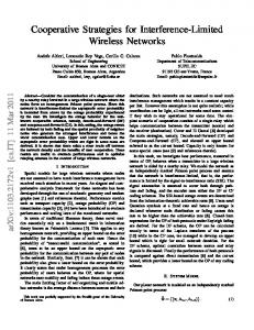
deployment of hierarchical networks results in high co-channel interference (CCI) which limits system performance. In the literature the issue of CCI has been identified for two-way relaying systems [11]–[13], however its effects have not been investigated for the hierarchical system architecture of interest. In this paper we investigate how CCI impacts on hierarchical networks and how its effects can be mitigated. We study the average maximum sum rate (AMSR) performance of a simple hierarchical network consisting of an HBS with two highly directional antennas, two interfering two-way RNs and two MSs. We propose two general cooperative strategies; the first is based on Decode-and-Forward (DF) with the aid of network coding and the second is based on Amplify-and-Forward (AF) with Network MIMO processing at the HBS. Furthermore we devise some communication protocols requiring two, three or four time slots that are combined with our proposed strategies. We show that for the considered system scenario the 2-slot protocols perform best. The DF-based strategy performs better in the low CCI regime while the AF-based strategy exploits CCI in the uplink and greatly outperforms DF when CCI is dominant. The remainder of this paper is structured as follows. In Section II the signal and system model is presented. In Sections III and IV the proposed schemes based on DF relaying combined with network coding and AF relaying coupled with Network MIMO are presented and discussed. In Section V simulation results are shown and in Section VI the paper is concluded. Notations: Vectors and matrices are denoted by boldface lowercase letters and boldface capital letters respectively. A [i, j] represents the ij-th element of a matrix. The transpose, transpose conjugate, the inverse and the pseudo-inverse of a matrix A are denoted by AT , AH , A−1 and A† respectively. The XOR operation is denoted by ⊕. Furthermore E [.] denotes expectation and C (x) , log2 (1 + x). II. S IGNAL AND S YSTEM M ODEL We consider a hierarchical system consisting of two singleantenna MSs (nodes 1 and 2), two half-duplex single-antenna RNs (nodes 5 and 6), and an HBS with two directional antennas which are assumed to create two non-interfering channels (designated as nodes 3 and 4) as shown in Fig. 1. The MS and RN antennas are assumed to be omni-directional. The HBS and the MS nodes want to exchange messages via
T
Fig. 1. The considered system scenario under a 2-slot protocol: an HBS with two directional antennas (nodes 3, 4), two MSs (nodes 1, 2), and two RNs (nodes 5, 6).
[x1 , x2 ] . Node 5 decodes symbols x1 , x3 treating h5,2 x2 as noise and node 6 decodes x2 , x4 treating h6,1 x1 as noise. In the second time slot nodes 5 and 6 transmit x5 = x1 ⊕ x3 and x6 = x2 ⊕ x4 respectively. Nodes 1 and 3 decode x5 and retrieve the symbol x3 and x1 respectively. Similarly, nodes 2 and 4 decode x6 and retrieve x4 and x2 respectively. We define some rate expressions for the multiple access (MAC) phase of the first time slot in the following, which ( ) |h |2 will be used as rate constraints later. C15 = 12 C |h 5,1|2 +1 , 5,2 ( ) ( ) |h |2 |h5,1 |2 +|h5,3 |2 C35 = 12 C |h 5,3|2 +1 , CM 5 = 12 C , 2 5,2 ) ( ( ) |h5,2 | +1 |h6,2 |2 |h6,4 |2 1 1 C26 = 2 C |h |2 +1 , C46 = 2 C |h |2 +1 and CM 6 = 6,1 ) 6,1 ( |h6,2 |2 +|h6,4 |2 1 C . The rate expressions for the broadcast 2 2 |h6,1 | +1 (BC)( phase )of the second( time slot) are defined (as: C53 = ) |h1,5 |2 |h2,6 |2 2 1 1 1 51 = 2 C |h |2 +1 , C62 = 2 C |h |2 +1 2 C |h3,5 | , C 1,6 2,5 ( ) 2 and C64 = 12 C |h4,6 | . B. 3-slot DF-XOR
the RN nodes; node 1 with node 3 and node 2 with node 4. Nodes 1 and 2 receive/cause interference from/to nodes 6 and 5 respectively. The wireless links between the HBS antennas and the RNs are defined as the backhaul network, while the links between the RNs and the MSs are defined as the access network. The wireless channels between any pair of nodes are assumed to experience flat fading. The channel coefficient between nodes k and n is hk,n = Γk,n
√ γ¯k,n
(1)
where Γk,n denotes the normalized fading coefficient and γ¯k,n denotes the average signal-to-noise ratio (SNR) of the link. Transmission is corrupted by unit variance zero-mean circularly symmetric additive white Gaussian noise (AWGN). The MS and HBS nodes are assumed to be transmitting T unit variance symbols grouped in vector x = [x1 , x2 , x3 , x4 ] . T The RN nodes receive the signal vector yR = [y5 , y6 ] . It should be noted that the elements of vectors x and yR can be transmitted and received in different time slots depending on the employed cooperative protocol.
According to this protocol, in the first time slot nodes 1 and 3 transmit symbols x1 and x3 respectively and RN 5 decodes them in the absence of CCI. In the second time slot nodes 2 and 4 transmit symbols x2 and x4 respectively and RN 6 decodes them also in the absence of CCI. In the third time slot nodes 5 and 6 transmit x5 = x1 ⊕ x3 and x6 = x2 ⊕ x4 respectively. Furthermore, nodes 1 and 3 decode x5 and retrieve the symbol x3 and x1 respectively. Similarly, nodes 2 and 4 decode x6 and retrieve x4 and x2 respectively. It should be noted that nodes 1 and 2 treat h1,6 x6 and h2,5 x5 as noise while decoding x3 and x4 . The rate expressions for the MAC phase of 3( the ) 2 slot protocol are the following: C15 = 31 C |h5,1 | , ( ) ( ) 2 2 2 C35 = 13 C |h5,3 | , CM 5 = 31 C |h5,1 | + |h5,3 | , ( ) ( ) 2 2 and CM 6 = C26 = 13 C |h6,2 | , C46 = 31 C |h6,4 | ( ) 2 2 1 for the BC phase 3 C |h6,2 | + |h6,4 | . The(rate expressions ) ) ( |h |2 2 1 are defined as: C53 = 3 C |h3,5 | , C51 = 31 C |h 1,5|2 +1 , 1,6 ( ) ( ) |h |2 2 C62 = 13 C |h 2,6|2 +1 and C64 = 13 C |h4,6 | . 2,5
III. DF
WITH
N ETWORK C ODING
In this section we present a cooperative strategy and some communication protocols based on DF. The RNs decode the wanted signals treating the received interference as noise. The decoded symbols are combined with the use of the bitwise XOR operation and forwarded to the destination nodes. Communication can take place in two, three or four time slots. As the number of time slots grows, the impact of CCI on the attained performance becomes less significant. However increasing the number of slots incurs a pre-log penalty that limits the achievable capacity. A. 2-slot DF-XOR In the first time slot the HBS transmits the symbol vector T xB = [x3 , x4 ] and the MSs transmit the symbol vector xU =
C. 4-slot DF-XOR The 4-slot protocol frees the system from CCI and serves as a performance benchmark. In the first time slot nodes 1 and 3 transmit symbols x1 and x3 respectively and RN 5 decodes them. In the second time slot node 5 transmits x5 = x1 ⊕ x3 and nodes 1 and 3 decode x5 and retrieve symbols x3 and x1 respectively. Similarly, in the third time slot nodes 2 and 4 transmit symbols x2 and x4 respectively and RN 6 decodes them. In the fourth time slot node 6 transmits x6 = x2 ⊕ x4 and nodes 2 and 4 decode x6 and retrieve symbols x2 and x4 respectively The rate expressions for the MAC phase of 4( the ) 2 slot protocol are the following: C15 = 41 C |h5,1 | , ( ) ( ) 2 2 2 C35 = 14 C |h5,3 | , CM 5 = 41 C |h5,1 | + |h5,3 | ,
( ) ( ) 2 2 C26 = 14 C |h6,2 | , C46 = 14 C |h6,4 | and CM 6 = ( ) 2 2 1 rate expressions for the BC phase 4 C |h6,2 | + |h6,4 | . The ( ) ( ) 2 2 are defined as: C53 = 14 C |h3,5 | , C51 = 14 C |h1,5 | , ( ) ( ) 2 2 C62 = 14 C |h2,6 | and C64 = 14 C |h4,6 | . T
Let r = [R1 , R3 , R2 , R4 ] be the vector containing the transmit rates of HBS and MS nodes. T Let b1 = [C15 , C35 , CM 5 , C26 , C46 , CM 6 ] , b2 = T [C53 , C51 , C64 , C62 ] be the vectors containing the rate constraints of the MAC and BC phases respectively. The maximum sum-rate can be expressed as RDF
=
max
Rk (2)
s.t. A r ≤ b1 I r ≤ b2 0 0 0 0 1 1
.
(3)
A. 2-slot AF In the first slot MS and HBS nodes transmit their symbols, grouped in vector x, and the RNs receive the following signal vector yR = HR x + nR
(4) [ ] H is a vector of AWGN coefficients, E nR nR = I,
HR =
h5,1 h6,1
h5,2 h6,2
h5,3 0
{∑ } ∑2 2 2 2 |H [1, n]| + 1, |H [2, n]| + 1 U U n=1 { n=1 } 2 2 Rn˜ B = diag |HB [1, 1]| + 1, |HB [2, 2]| + 1 . (9) As MS nodes are remote they can only process signals individually. Node 1 decodes the message of node 3 and node 2 that of node 4. For the 2-slot protocol the achievable rates for the transmission of nodes 3 and 4 are Rn˜ U = diag
(
In the present section it is proposed that AF relaying can be applied combined with Network MIMO in order to mitigate the effects of CCI. The proposed strategy can utilise two or three time slots.
[
˜ U = HU HR , H ˜ B = HB HR , n ˜U = HU nR + nU , where H ˜B = HB nR + nB and n ] [ α5 h1,5 α6 h1,6 HU = α5 h2,5 α6 h2,6 (8) [ ] α5 h3,5 0 . HB = 0 α6 h4,6
) ˜ U [1,3]|2 |H 2 ˜ ˜ ( |HU [1,2]| +|HU [1,4]2| +Rn˜ U [1,1] ) ˜ H | U [2,4]| R4 = 21 C . 2 ˜ ˜ U [2,3]|2 +Rn H [2,1] + | U | |H ˜ U [2,2]
R3 = 21 C
IV. AF WITH N ETWORK MIMO
where nR and
(7)
The noise covariances are
4 ∑ k=1
where I is the identity matrix and 1 0 0 0 1 0 1 1 0 A= 0 0 1 0 0 0 0 0 1
˜U x + n ˜U yU = HU HR x + HU nR + nU = H ˜B x + n ˜B ˜yB = HB HR x + HB nR + nB = H
0 h6,4
] .
(5)
Note that the zero elements in HR reflect the fact that the HBS antennas (nodes 3 and 4) are assumed not to interfere. In the second time slot both RNs transmit an amplified version of their received signal and the amplification factors take the following values for RN nodes 5 and 6 [ ]−1/2 2 2 2 α5 = |h5,1 | + |h5,2 | + |h5,3 | + 1 [ ]−1/2 2 2 2 α6 = |h6,1 | + |h6,2 | + |h6,4 | + 1 .
2
(10)
˜ U [1, 1] x1 Note that nodes 1 and 2 subtract self-interference H ˜ U [2, 4] x2 respectively. The HBS receives two signals and H from nodes 3 and 4 containing [ both x]1 and x2 , which are ˜B = H ˜ B1 H ˜ B2 where jointly processed. Let H [ ] α5 h3,5 h5,1 α5 h3,5 h5,2 ˜ HB1 = α6 h4,6 h6,1 α6 h4,6 h6,2 (11) [ ] α h h 0 5 3,5 5,3 ˜ B2 = H . 0 α6 h4,6 h6,4 The sub-matrix HB2 represents self-interference for nodes 3 and 4 and therefore its effects can be cancelled. In consequence only HB1 affects the achievable rate of nodes 1 and 2 whose signals are jointly decoded by nodes 3 and 4. We assume that HB1 is fully known by the HBS. In the case of linear detection a beamforming matrix W = [w1 , w2 ], which is a function of HB1 representing the global channel state information (CSI), is designed by the HBS and applied to the received signals. w1 , w2 ∈ C2×1 denote the beamforming vectors corresponding to the signals transmitted by nodes 1 and 2 respectively. The finally extracted signal can be expressed in vector form as
(6)
The MS and the HBS antennas receive the signal vectors T T yU = [y1 , y2 ] and ˜ yB = [˜ y1 , y˜2 ] respectively, which can be expressed as
˜ B1 xU + W n ˜B yB = W ˜yB = W H T
(12)
˜ B1 = [h1 , h2 ] where hk where xU = [x1 , x2 ] . Let H corresponds to node k. The achievable rate for nodes k = 1, 2 is
) T 2 w hk 1 k Rk = C (13)
2 wT hn,n̸=k 2 + wT 2 Rn˜ [k, k] B k k 2
2 where factors wTk hn,n̸=k and wTk Rn˜ B [k, k] correspond to inter-node interference and noise enhancement respectively, which both have a detrimental effect. We assume that the HBS obtains perfect global CSI (matrix HB1 ) and acts as a Network MIMO central unit. The beamforming matrix can be based on Zero-Forcing (ZF), ˜ †B1 , or the Minimum Mean Square Error where W = H ( H )−1 ˜ B1 H ˜ B1 + RB ˜ B1 . Detection (MMSE), where W = H H
The HBS receives in the second time slot a signal from node 3 and in the third time slot a signal from node 4. These signals are jointly processed in the third time slot with the use of Network MIMO techniques as above. Therefore achievable rate for nodes k = 1, 2 is
can be improved further if it is performed in a successive fashion, i.e., the detected symbols are subtracted from the remaining received signal. This frees the signal from some interference components and can enhance the achieved capac˜ B1 = [h1 , h2 ] is ordered so that ity. The composite channel H ∥h1 ∥ ≤ ∥h2 ∥. The beamforming vector wk corresponding to ˆ †k for ZF and Wk = node k is the first row of matrix Wk = H ( H )−1 H ˆk H ˆ k + RB ˆ k for MMSE, where H ˆ k = [hk , hk+1 ]T . H H
For simplicity, we assume a symmetric interfering two-way relay channel; the wireless links of the access network, the backhaul network and the interfering links experience the same average SNR, i.e., γ¯1,5 = γ¯5,1 = γ¯2,6 = γ¯6,2 = γ¯AC , γ¯5,3 = γ¯3,5 = γ¯4,6 = γ¯6,4 = γ¯BH , and γ¯5,2 = γ¯2,5 = γ¯1,6 = γ¯6,1 = γ¯I . Fig. 2 plots the total AMSR versus the average SNR γ¯I for the considered schemes when backhaul and access networks experience identical average SNR γ¯BH = γ¯AC = 10 dB and Rayleigh fading, i.e., Γk,n ∼ N C (0, 1). As can be seen from Fig. 2, in the low CCI regime (¯ γI < 0 dB) the 2slot DF-XOR approach performs better. When CCI becomes dominant, the 2-slot AF scheme perform better as it effectively exploits interference through Network MIMO processing at the HBS. Amongst the AF schemes, the ones taking advantage of SIC are superior. Although the 3-slot schemes avoid some interference, they perform worse than those based on 2-slots as the pre-log penalty of 31 is dominant in the considered scenario. The performance of the 4-slot DF-XOR scheme is not affected by CCI and serves as a baseline for comparisons. Fig. 3 plots the AMSR for the downlink and uplink separately, for the 2slot and 3-slot DF-XOR and the 2-slot AF-LMMSE scheme. Uplink rate is generally higher as the directional HBS antennas eliminate CCI in the second time slot. The AMSR deteriorates when CCI becomes stronger for all cases apart from the uplink of the AF scheme. The AMSR for the uplink of AF improves as γ¯I increases because the HBS jointly processes the received signals by nodes 3 and 4 using Network MIMO techniques (CCI turns to an advantage). Fig. 4 plots the total AMSR for the same schemes when the average SNR of the backhaul network is γ¯BH = 20 dB and that of the access network is γ¯BH = 10 dB. This is justified by the fact that the backhaul network can be planned to have links of high quality as the positions of the RNs relative to the HBS can be selected appropriately. As expected, the performance of all schemes improves when the quality of backhaul links increases. Furthermore the AF protocols perform relatively better than the case of Fig. 2.
(
With successive interference cancellation (SIC), each node expreriences only interference from nodes with higher index. This results in improved performance compared with linear detection. The achievable sum-rate is RAF =
4 ∑
Rk .
(14)
k=1
B. 3-slot AF According to this protocol, in the first time slot MS and HBS nodes transmit their symbols and the received signal by the RNs is given by (4). In the second time slot RN 5 transmits with the amplification factor α5 and RN 6 remains silent. In the third time slot RN 6 transmits with the amplification factor α6 and RN 5 remains silent. The employed amplification factors are given by (6). The received signals by the MSs and the HBS antennas (vectors yU and ˜yB respectively), accumulated in the second and third time slot, are as in (7). It should be noted that HR , HB are as in (5) and (8) respectively, where HU is as follows [ ] α5 h1,5 0 HU = . (15) 0 α6 h2,6 The noise covariances are { } 2 2 Rn˜ U = diag |HU [1, 1]| + 1, |HU [2, 2]| + 1 { } 2 2 Rn˜ B = diag |HB [1, 1]| + 1, |HB [2, 2]| + 1 .
(16)
The achievable rates for the transmission of nodes 3 and 4 are ( ) ˜ U [1,3]|2 |H R3 = 13 C 2 ˜ ( |HU [1,2]| +Rn˜2U [1,1] ) (17) ˜ U [2,4]| |H . R4 = 13 C 2 ˜ U [2,1]| +Rn |H ˜ U [2,2]
1 Rk = C 3
(
) T 2 w hk k .
wT hn,n̸=k 2 + wT 2 Rn˜ [k, k] B k k
(18)
The achievable rates can be enhanced with the application of SIC techniques as described above. V. N UMERICAL R ESULTS
VI. C ONCLUSIONS In this paper we investigated ways of mitigating CCI in a simple dual-hop hierarchical network consisting of an HBS with two directional antennas, two RNs and two MSs. We
Average SNR
=10dB
AC
Average SNR
=10dB
tocols based on 2, 3 or 4 time slots and compared their performance as a function of the interference strength. It was shown that the 2-slot protocols perform generally better than the 3-slot and 4-slot ones. The DF-XOR scheme achieves superior performance when CCI is weak while the AF with Network MIMO performs better in the high CCI regime by turning CCI into an advantage. This is due to the fact that Network MIMO essentially exploits interference at the cost of requiring accurate CSI at the HBS.
BH
Average Maximum Sum Rate [Bits/sec/Hz]
4 3.5 3 2.5 2 1.5 1 0.5 0 −20
Fig. 2.
2S−DF−XOR 2S−AF−MMSE−SIC 2S−AF−LMMSE 3S−AF−MMSE−SIC 3S−AF−LMMSE 3S−DF−XOR 4S−DF−XOR −15
−10 −5 0 5 10 Average SNR of Interfering links [dB]
15
20
The total AMSR versus γ ¯I when γ ¯BH = γ ¯AC = 10 dB. Average SNRAC=10dB
Average SNRBH=10dB
Average Maximum Sum Rate [Bits/sec/Hz]
2.5
2
R EFERENCES
1.5
1
0.5
0 −20
UL DL UL DL UL DL −15
2S−DF−XOR 2S−DF−XOR 2S−AF−LMMSE 2S−AF−LMMSE 3S−DF−XOR 3S−DF−XOR −10 −5 0 5 10 Average SNR of Interfering links [dB]
15
20
Fig. 3. The AMSR of the uplink and downlink of 2S-DF-XOR, 3S-DF-XOR and 2S-AF-LMMSE versus γ ¯I when γ ¯BH = γ ¯AC = 10 dB. Average SNRAC=10dB
Average SNRBH=20dB
5.5
Average Maximum Sum Rate [Bits/sec/Hz]
5 4.5 4 3.5 3 2.5 2 1.5 1 0.5 −20
ACKNOWLEDGMENTS This work was supported by the European Commission’s seventh framework programme (FP7/2007-2013) under grant agreement no 248267 (BuNGee) and the EPSRC under the project “UK-China Science Bridges: R&D on (B)4G Wireless Mobile Communications” (UC4G) with grant reference EP/G042713/1. The work by M. Tao was supported by the National Natural Science Foundation of China under grant 60902019 and the Shanghai Pujiang Talent Program under grant 09PJ1406000.
2S−DF−XOR 2S−AF−MMSE−SIC 2S−AF−LMMSE 3S−AF−MMSE−SIC 3S−AF−LMMSE 3S−DF−XOR 4S−DF−XOR −15
−10 −5 0 5 10 Average SNR of Interfering links [dB]
15
20
Fig. 4. The total AMSR versus γ ¯I when γ ¯BH = 20 dB and γ ¯AC = 10 dB.
considered two general cooperative strategies, one based on DF with network coding and another based on AF with Network MIMO. We devised a number of cooperative pro-
[1] J. N. Laneman, D. N. C. Tse, and G. W. Wornell, “Cooperative diversity in wireless networks: Efficient protocols and outage behavior,” IEEE Transactions on Information Theory, vol. 50, no. 12, pp. 3062–3080, Dec. 2004. [2] R. Nabar, H. Bolcskei, and F. Kneubuhler, “Fading relay channels: performance limits and space-time signal design,” IEEE Journal on Selected Areas in Communications, vol. 22, no. 6, pp. 1099–1109, Aug. 2004. [3] A. Papadogiannis, G. C. Alexandropoulos, A. G. Burr, and D. Grace, “Bringing mobile relays for wireless access networks into practice– learning when to relay,” submitted to IET Communications, Feb. 2011. [4] A. Papadogiannis, “Systems and techniques for Multicell-MIMO and cooperative relaying in wireless networks,” Ph.D. dissertation, TELECOM ParisTech, France, Dec. 2009. [5] Z. Roth et al., “Vision and architecture supporting wireless Gbit/sec/km2 capacity density deployments,” in Proc. Future Networks and Mobile Summit (FUNEMS 2010), Florence, Italy, June 2010. [6] A. Papadogiannis and A. G. Burr, “Multi-beam assisted MIMO - A novel approach to fixed beamforming,” in Proc. Future Networks and Mobile Summit (FUNEMS 2011), Warsaw, Poland, June 2011. [7] B. Rankov and A. Wittneben, “Spectral efficient signaling for halfduplex relay channels,” in Asilomar Conference on Signals, Systems and Computers (ASILOMAR 2005), Pacific Grove, USA, 28 - november 1 2005, pp. 1066 – 1071. [8] J. Liu, M. Tao, and Y. Xu, “Rate Regions of a Two-Way Gaussian Relay Channel,” in Proc. International Conference on Communications and Networking in China (CHINACOM 2009), Xi’an, China, August 2009. [9] F. Negro, I. Ghauri, and D. Slock, “Maximum weighted sum rate multiuser MIMO amplify-and-forward for two-phase two-way relaying,” in Proc. IEEE Personal Indoor and Mobile Radio Communications (PIMRC 2010), Istanbul,Turkey, Sept. 2010. [10] E. Yilmaz, R. Zakhour, D. Gesbert, and R. Knopp, “Multi-pair two-way relay channel with multiple antenna relay station,” in Proc. International Conference on Communications (ICC 2010), Cape Town, South Africa, may 2010, pp. 1–5. [11] I. Maric, R. Dabora, and A. Goldsmith, “On the capacity of the interference channel with a relay,” in Proc. International Symposium on Information Theory (ISIT 2008), Toronto, Canada, july 2008, pp. 554–558. [12] E. Yilmaz, R. Knopp, and D. Gesbert, “Interference Two-Way Relay Channel with Three End-nodes,” in Proc. IEEE International Symposium on Information Theory (ISIT 2011), St. Petersburg, Russia, Aug. 2011. [13] R. Knopp, “Two-way radio networks with a star topology,” in International Zurich Seminar on Communications (IZS 2006), Zurich, Switzerland, march 2006, pp. 154 –157.