ECOC 2009, 20-24 September, 2009, Vienna, Austria
Paper 5.3.1
Efficient ROADM-ring Connecting Node Switch Architecture that Utilizes Waveband Routing and its Realization with PLC Technologies Kiyo Ishii(1), Osamu Moriwaki(2), Hiroshi Hasegawa(1), Ken-ichi Sato(1), Yoshiteru Jinnouchi(3) Masayuki Okuno(3), (2) Hiroshi Takahashi (1) (2)
Nagoya University, Furo-cho, Chikusa-ku, Nagoya, 464-8603 Japan,
[email protected] NTT Photonics Laboratories, Nippon Telegraph and Telephone Corporation, (3) NTT Electronics
Abstract An efficient ROADM-ring connecting node architecture is proposed that utilizes waveband routing and achieves small footprint and cost-effectiveness. The key component devices are implemented using PLC technologies and the system performance is experimentally verified.
978-3-8007-3173-2 © VDE VERLAG GMBH
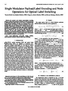
rings. Based on this achievement, we implemented the key components of the ring connecting HOXC system. This switch architecture is shown to achieve 60% switch scale reduction compared to a single layer architecture with the same routing capability. Their optical performance was tested and shown to be satisfactory for practical applications. Proposed HOXC architecture Figure 1 depicts two- and three- ring connecting nodes. Other nodes than the ring connecting node ring connecting node (cross-connect) ROADM
(a) two-ring connection (b) three-ring connection Fig. 1: Ring connecting nodes
8-arrayed 4x4 SW
8-arrayed 1x8 AWGs
λ1SW
λ8SW
WXC WBXC WB1 SW
WB5 SW 7[cm] 3[cm]
Introduction The large scale deployment of reconfigurable optical add-drop multiplexer (ROADM)-based ring networks has recently started in North America and Japan. The ring networks will be utilized extensively in network, long-haul, metro-core metro-edge, and metro-access part, to create robust large bandwidth networks. At present, ring interconnection is done in an electrical layer with OE/EO conversion and electrical switches. Removing the costly and power consuming electrical stage can be realized by exploiting optical path routing using OXC. The OXC architectures that utilize multiple large scale 1xN (N>6-16) Wavelength Selective Switches (WSS) or optical matrix switches have been investigated, however, the expected higher costs needed to create the OXCs prevented their introduction. Waveband path (bundle of wavelength paths) technology development has recently advanced1, and it was demonstrated that the Hierarchical OXC (HOXC) architecture can substantially reduce OXC switch scale. This is true for WSS-based2 and matrix switch-based3 OXC architectures. Applying the waveband routing capabilities we have proposed a 2ring connecting node architecture that partially applies waveband routing4. It was shown that the node switch scale can be greatly (more than 80 % when inter-ring traffic is 60 %) reduced. The requirements for the reduction are; (i) wavelengths should be previously arranged into two groups that are used within a ring and between rings, (ii) Inter-ring traffic should be routed as a waveband at the ring connecting node, (iii) traffic within each ring is routed as wavelength paths, and (iv) 2-ring connecting nodes. We have recently succeeded in developing a new efficient optical path demand accommodation algorithm5 that imposes no constraint on wavelength assignment regarding inner- and inter- ring traffic. The waveband routing is applied to all traffic at the ring connecting node; wavelength level grooming can be done if necessary. The algorithm can be extended to multiple-ring connection. The performance of the algorithm has been proven and the optical path demand accommodation efficiency offset was proven to be marginal5 compared to single-layer optical path
8x8 switches
6-input WB MUX/DEMUX
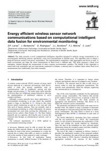
WXC: wavelength cross-connect WBXC: waveband cross-connect Fig. 2: Proposed HOXC node switch architecture and the functional partitioning for PLC chip fabrication
ECOC 2009, 20-24 September, 2009, Vienna, Austria
Paper 5.3.1
Tab. 1: Implemented component chips and number of chips needed for the implemented HOXC
# of chip 1 1 5 3 (2.5) 5
TLS ch16
1565nm
17 33 49 65 81 97 113 Path No.
Extinction Ratio (dB)
Insertion Loss (dB)
1530nm
80 60 40 20 0
1550nm
1530nm
1565nm
17 33 49 65 81 97 113 Path No.
Transmittance [dB]
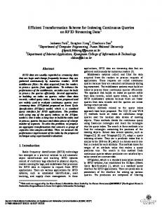
(a) insertion loss (b) extinction ratio Fig. 3: 8-arrayed 4x4 switch: measured values 0 -10 -20 -30 -40 -50
1538
1540
1542
1544
1546
Wavelength [nm] Fig. 4: Transmittance of 8-arrayed 1x8 AWG
978-3-8007-3173-2 © VDE VERLAG GMBH
6x6 HOXC
BPF EDFA
VOA
Receiver PM
Fig 5: Experimental setup for testing proposed HOXC node measured
Performance of developed devices The waveband MUX/DEMUX architecture was that proposed previously6. Since the device accommodates six input/output fibers, only two chips are necessary. The performance is equivalent to that in Ref. 6. Figure 3 shows the insertion loss and extinction ratios of eight-arrayed 4x4 switches integrated on a chip (16 combinations x 8=128). Figure 4 shows transmittance of an eight-arrayed 1550nm
3dB channel bandwidth 1nm
λ=1543.730[nm]
are conventional ROADM nodes (WSS-based, matrix switch based, wavelength blocker based; any type is acceptable) that perform wavelength level routing. Figure 2 depicts the proposed node switch architecture (node-degree is 6) that can connect up to three rings; each ring consists of two bidirectional fibers. Here the ratio of add/drop wavebands to total incoming wavebands is set to 1/3. The simple architecture allows us to make the best use of PLCs, which have no moving mechanical parts, require no adjustment, and are very compact with functional integration, which will lead to higher reliability and lower cost. The HOXC consists of waveband MUX/DEMUX, waveband path switch, wavelength MUX/DEMUX, and a wavelength path switch. Each input fiber carries 40 wavelengths (191.8+0.1xn [THz]; n=0-39) that constitute 5 wavebands, each with 8 wavelengths. Fig. 2 shows the functional partitioning used in implementing the PLC chips, and Table 1 summarizes implemented component chips and the number of chips needed for the HOXC. The data shown confirms that the proposed architecture requires significant less hardware than conventional single layer OXCs that use many WSSs or matrix switches to create 6-degree optical cross-connect systems.
3 2.5 2 1.5 1 0.5 0
LN MOD
WXC
WXC
WXC
WBXC
WBXC
WBXC
(a)
(b) Fig. 6: Switch setup
Bit Error Rate
function 6-input WB-MUX 6-input WB-DEMUX 8x8 switch 8-arrayed AWG (1x8) 8-arrayed 4x4 switch
9.95328 Gbit/s PRBS 231-1 PPG
(c)
10-6 10-7 10-8 10-9 10-10 10-11 10-12 -32
B to B switch setup (a) switch setup (b) switch setup (c) -31
-30
-29
-28
-27
Average Received Power [dBm] Fig. 7: Measured BER
1x8 athermal AWGs integrated on a chip. The arrayed arrangement and the athermal characteristic contribute to lessen power consumption and overall footprint. Details of the device characteristics will be published elsewhere. Transmission Performance of the Node Figure 5 depicts the experimental setup used to measure BER. Three different routing arrangements were tested as shown in Fig. 6; (a) optical path is routed via WBXC, (b) optical path is groomed at the node (transferred to different waveband in a different fiber), and (c) multiple wavelength paths are traversed to evaluate the effects of crosstalk. Figure 7 shows typical BER results (ch16; 1543.730[nm]). The maximum power penalty at bit error rate of 10-9 was 0.8dB, which will be acceptable for the envisaged applications. Conclusions The ring connecting node architecture that realizes a small footprint and cost-effectiveness was proposed. The key component devices were implemented using PLC technologies and system performance was experimentally verified. Acknowledgement: This work was partly supported by JST
References 1 K. Sato et al., IEICE Trans. Commun., vol. E90B(2007), pp. 1890-1902 2 S. Mitsui et al., Photonics in Switching 2008, paper S-04-1, Sug. 2008. 3 S. Kakehashi et al., IEICE Trans. Commun., vol. E91-B(2008), pp. 3174-4184 4 K. Ishii et al., ECOC2007, paper 10.5.2, Sept. 2007. 5 K. Ishii et al., submitted to ECOC2009. 6 S. Kakehashi et al., IEEE Photonics Tech. Letters, vol. 19(2007), no. 16, pp. 1197-1199