number of candidate paths k using incremental SAT-solving. In the manner of a binary .... the solver can identify more complex implications even on related lines.
Efficient SAT-based Dynamic Compaction and Relaxation for Longest Sensitizable Paths Matthias Sauer∗ ∗
Sven Reimer∗
Tobias Schubert∗
Albert-Ludwigs-Universit¨at Freiburg Georges-K¨ ohler-Allee 051 79110 Freiburg, Germany
{ sauerm ∣ reimer∣ schubert ∣ becker }@informatik.uni-freiburg.de
Ilia Polian†
Bernd Becker∗
†
University of Passau Innstraße 43 94032 Passau, Germany ilia.polian @uni-passau.de
for stuck-at-faults, which use SAT-solvers [8], creates SATinstances that iteratively target additional faults individually. The compaction of delay fault models is especially challenging, as multiple timeframes and stringent test requirements need to be considered. Approaches in [9], [10] keep a pool of paths and try to generate test patterns that sensitize several paths from the pool together by combining a structural compatibility analysis with ATPG. The procedure in [11] aims at selecting paths with matching crosspoints to yield a compact test set with high fault coverage. A central requirement for any practical test strategy is compatibility with state-of-the-art test compression methods [12], [13], [14]. Encoded test data is transmitted from the tester to the chip where it is decompressed by on-chip decoders and fed into the scan chains. The efficiency of test compression heavily depends on a large number of don’t-care values (Xes) being present in the test data. Unfortunately, compaction tends to eliminate many Xes, resulting in test sets that are smaller but much harder to compress. Test relaxation methods that introduce Xes at positions not essential for detection [15], [16] are needed to combine compaction with test compression. I. Introduction We present a small delay fault oriented dynamic comHigh-performance and low-power design methods often paction method that compacts long sensitizable paths. The result in circuits with a large number of near-critical paths. method generates a SAT-instance that encodes the circuit By employing versions of primitive cells with different VT , or functionality and sensitization rules for a group of target by using body biasing techniques, designers can realize local paths. By maximizing the number of paths that are sensitized power-performance trade-offs, choosing for each gate whether by a single test pattern pair, highly compacted test sets are it should be slow and power-efficient or fast and power- generated. In addition, efficient SAT-based test pattern relaxhungry. Slow versions of gates are consequently used on short ation is used to generate high-quality test cubes. Extensive paths, such that the delays of such paths become comparable experimental results on academical and industrial benchmark to the critical path delay. High-quality testing of small- circuits demonstrate the effectiveness of the approach. delay faults under process variations requires sensitization The remainder of the paper is structured as follows. of several, ideally all, near-critical paths through the fault Section II explains the preliminary work. An overview of the location. Since the number of such paths is so high, using method is given in Section III. The details of our approach are one test pair per path will imply excessive pattern count and explained in Section IV. Experimental results are reported test application time. Therefore, it is desirable to generate in Section V and Section VI concludes the paper. compact test pair sets where one pair sensitizes multiple long II. Preliminaries paths and thus detects many small-delay faults along these A. SAT paths. This problem is related to test compaction. Static compaction [1], [2] starts with existing test patterns Given a propositional formula φ, an assignment A is a and tries to merge them by finding common non-conflicting function A ∶ V → {0, 1}, where V is the set of Boolean inputs. In contrast to static compaction, dynamic compaction variables, which occur in φ. The SAT problem is looking [3], [4] yields new test patterns that target several faults at for an assignment A for φ, such that φ is satisfied. If such the same time. Often, these methods are combined with fault an assignment exists we say A is a model for φ. Usually, dropping [5], where simulation is used to detect random fault the formula φ is given in conjunctive normal form (CNF ), detection. Previous work on test pattern compaction [6], [7] which is a conjunction of disjunctions of literals. A literal
Abstract— Comprehensive coverage of small-delay faults under massive process variations is achieved when multiple paths through the fault locations are sensitized by the test pair set. Using one test pair per path may lead to impractical test set sizes and test application times due to the large number of near-critical paths in state-of-theart circuits. We present a novel SAT-based dynamic test-pattern compaction and relaxation method for sensitized paths in sequential and combinational circuits. The method identifies necessary assignments for path sensitization and encodes them as a SAT-instance. An efficient implementation of a bitonic sorting network is used to find test patterns maximizing the number of simultaneously sensitized paths. The compaction is combined with an efficient lifting-based relaxation technique. An innovative implication-based path-conflict analysis is used for a fast identification of conflicting paths. Detailed experimental results demonstrate the applicability and quality of the method for academical and industrial benchmark circuits. Compared to fault dropping the number of patterns is significantly reduced by over 85% on average while at the same time leaving more than 70% of the inputs unspecified.
978-3-9815370-0-0/DATE13/©2013 EDAA
Table I Sensitization conditions for AND/NAND gates Type
If on-path transition is
Off-path inputs are set to
Additional conditions
strong non-robust
0→1 1→0
U1 H1
– –
restricted functional
0→1 1→0
U1 XX
transition at gate output
explained in detail in [21], [22]. H1 stands for a signal that stabilizes to logic 1 in both cycles after application of v1 and v2 . U1 stands for a signal that eventually stabilizes at logic 1 in the second cycle without imposing conditions on the first cycle. Finally, XX stands for a signal on which no conditions are imposed at all. The requirements for OR/NORgates are defined analogously. Due to their more stringent requirements on the side inputs, strong non-robust path sensitization reduces the probability of a test invalidation by e. g., glitches and offer hence a higher test quality than restricted functionally sensitized paths.
is a variable v or its negation ¬v. A disjunction of literals III. Overview of the method is also called a clause, which is often written as a set of literals. A circuit can be transformed into a CNF by using The main objective of our proposed dynamic compacTseitin-encoding [17], which uses separate variables for each tion and relaxation method is to sensitize all given target circuit line. The resulting CNF size is linear in the circuit paths P T with as few patterns as possible and minimize size. the number of specified primary inputs in addition. Figure 1 A clause ce is empty, if all literals in ce are assigned to 0. gives an overview of the algorithm. We say a clause c implies a literal l, if only l ∈ c is not In the path generation phase, we use the in-house SATassigned and all other literals l′ ∈ c are assigned to 0. As based path generation tool PHAETON. PHAETON reads a resulting implication l is assigned to 1. sequential circuit given as gate-level net list along the timing Consider a directed acyclic graph G = (V, E), where the specification (given as SDF-file) and the fault list. For each vertices V indicate assignments of literals, and edges E gate g in the fault list, the longest sensitizable path through indicate implications. Given a clause c = {l1 , . . . , ln }, where g is generated. l1 is an implication (and consequently l2 , . . . , ln are assigned In a preprocessing phase we simplify the generated list of to 0), G contains for every vertex li , i ∈ {2, . . . , n} an edge to longest sensitizable paths. A given path may be the longest the vertex l1 . This graph is called implication graph and is path for several of the gates. As different instances of the used to generate a reason in case an empty clause is produced same path can be compacted trivially without increasing the by a SAT-solver. A reason is a set of variables VR ∈ V, whose fault coverage, we remove duplications, and just keep the assignment is responsible for the empty clause. In general, unique paths. Furthermore, we recognized in our experiments there are many reasons for one empty clause. that paths with a high probability to conflict with other paths Modern SAT-solvers are based on the DPLL [18] algorithm. (c.f. IV-A), are also harder to compact and should therefore They basically execute a loop consisting of (1) making be considered early in the compaction process. Therefore a decision, (2) propagating the decision (processing all we determine the number of conflicting paths for each path implications forced by the current decision), and (3) if a (c.f. IV-B). Hereupon the paths are sorted by this number, conflict occurred, resolving the conflict by determining the resulting in an ordered list of target paths P T . reason for the empty clause. After unassigning all wrong In the dynamic compaction phase we utilize modern SATvariables the search process continues until a model has solver techniques to generate test patterns that maximize been found or the instance has been proven unsatisfiable the number of target paths sensitized at the same time. (unresolvable conflict). First, we perform a path selection, where a list of required paths P R ⊆ P T , which we want to sensitize, and a list B. Path Sensitization of candidate paths P C ⊆ P T , which should be sensitized A path p is defined by a sequence of gates g1 , . . . , gk , in addition to the required paths P R , are extracted. The such that the input of gj is driven by the output gj−1 for number of candidates is limited by a user-defined value cmax , all 1 < j ≤ k. Intuitively, a path p is sensitized by a test which serves as a trade-off between quality and performance. pair (v1 , v2 ) if a transition at its input g1 propagates to its Initially, we pick the first uncompacted path in the ordered output gk , thus exposing delays along the path. Path-oriented path list P T as the required path in P R , and choose the next ATPGs [19], [20] generate test pairs for a delay fault on gate g cmax paths in P T as candidate paths P C . that sensitize a number of longest paths through g. If the In the path compaction phase (c.f. IV-C), a SAT-instance additional delay introduced by a fault is greater than the is generated, which is satisfied iff 1) all paths in P R can slack of one of these paths, the corresponding test pair is be sensitized at once and 2) k paths out of P C can be likely to detect the fault. Hence, the excitation of longer paths sensitized in addition. As a greedy heuristic, we maximize the leads generally to an improved small delay fault detection number of candidate paths k using incremental SAT-solving. quality. In the manner of a binary search, we solve the instance with A path p is formally defined to be sensitized by a test the same set of paths but with different values for k until pair (v1 , v2 ) if it launches a transition at g1 and justifies the maximum value for k has been found. If an instance is certain sensitization conditions on the off-path inputs of satisfiable, a test pattern AT P can be extracted from the all gates of p. The sensitization conditions considered in model returned by the SAT-solver. This pattern sensitizes this work are shown in Table I for AND/NAND gates and all required paths and k candidate paths.
Path Generation Delay data
Fault list
Circuit data
Longest sensitizable paths
Path generator
Preprocessing
Identify conflicting paths
Sort paths
Unique paths
Dynamic Compaction
PT Reset pattern
Path selection
Yes
P / P Dynamic path R
C
compaction
Yes No
Remaining paths?
Pattern extendable?
Path dropping
No Relaxation Test pattern relaxation
Figure 1.
Output final test cubes
Dynamic compaction and relaxation flow
A B C D
V1A V2A
g1
V1B V2B V CV C 1
2
g2
V1D V2D Figure 2.
g3 V11 V21
V13 V23
g4 V4V4 1
V12 V22
2
p1 p2
X Y
Path sensitization example
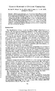
IV. Details of the method A. Encoding of path sensitization Figure 2 shows an example circuit instance consisting of the inputs A, . . . , D, AND-gates g1 , . . . , g4 and the outputs X, Y . Path p1 , given by a rising transition along the gates B, g1 , g3 , X and path p2 that is defined by a rising transition at C, g2 , g4 , Y are indicated by thick lines. For each line in the example, the logic value upon application of the first and the second test pattern is given by thick lines inside the boxes. Although both paths are not directly connected, they are partially influenced by the same signals, e. g., the output of gate g1 . Despite this fact, it is possible to sensitize both paths at the same time with the given test pattern. For each path p we identify the set of sensitization logic constraints Lp = l1p , . . . , lnp that need to hold in order to guarantee sensitization of p under the selected sensitization conditions, i. e. strong-non-robust or restricted functional sensitization. Based on this logic constraints, a decision variable sp indicates whether a path p is sensitized as defined as follows: sp ⇔ l1p ∧ . . . ∧ lnp (1)
In addition, a forward-looking simulation-based path dropping is performed to identify paths that are not in P C but still sensitized by the returned test pattern by chance. If there are remaining target paths P T that have not been tried to merge into the current test pattern, the current pattern may be extendable. Therefore, we extend the list A list of paths P = p1 , . . . , pn is compatible with each of required paths by the newly sensitized candidate paths other, if a test pattern pair exists, such that each path’s P R = P R ⋃ P C and select new candidate paths P C from P T . logic constraint can be met at the same time, i. e. As before, we create the corresponding SAT-instance and sP = (sp1 ∧ . . . ∧ spn ) (2) maximize the number of newly compacted paths. This step T is repeated until each path in P is conflicting with at least does hold. Otherwise, the paths in P are conflicting. one path in P R , i. e. P R can not be extended anymore. Note that the test compaction is dynamic and hence the pattern B. Implication-based path-conflict analysis may change in every step of this procedure. The implication-based path-conflict analysis identifies If the pattern is not extendable anymore, the compacted conflicting paths very efficiently employing the infrastructure paths are removed from P T and the current test pattern is of the used SAT-solver. marked as representative for these compacted paths. If P T is At first, a general SAT-instance ξ(E, sP ) is generated, not empty, the pattern is reset for the following steps and we that encodes the logic of the circuit for two timeframes (E). start over with the path selection, choosing a new required In addition, for each path pi ∈ P we encode spi according path and cnew candidate paths from P T . This loop repeats to Equation 1. Based on this general instance, we pass the until all initial target paths are covered by at least one test SAT-solver a path spj variable as an assumption. The solver pattern. can identify the implications of requiring spj to hold and In order to increase the compatibility of the generated therefore can identify which of the spi variables are implied test patterns with on-chip compaction techniques like LSFR- to be 0. Hence, we can identify the paths that are conflicting based test generation in a BIST environment, we apply with pj directly by looking at implied variables in the SATtest pattern relaxation (c.f. IV-D) for each compacted test solver. pattern. That way, we obtain test cubes that are guaranteed In addition to the direct implications on the logic constraints, to sensitize all required paths. Hence, the method is highly the solver can identify more complex implications even on flexible and can be easily combined with refilling techniques related lines. For example, if a gate input has a controlling to optimize secondary objectives. input constraint, the output of the gate can be determined.
pn
pi
p1
...
p1
Flip-Flops
pi
...
s
Flip-Flops
pi
...
Bitonic Sorting Network
...
s
...
... ...
soi
Primary inputs
p1
so1
pn
pn
son
s
Maximization
Figure 3.
Two-pattern delay test
solver, the test pattern AT P is obtained by extracting the logic values of the inputs. Furthermore, the sensitized paths C are identified as their spi -variables are set to 1. As described in section IV-B modern SAT-solvers are tuned to detect implications very efficiently. Therefore many of the lines are set to defined values, big parts of the circuit are decided, and consequently the level of complexity is reduced.
Illustration of SAT-instance generation
Likewise, if a gate output has a non-controlling output constraint, each input must be set accordingly. Although our implication-based path-conflict analysis may miss some conflicting paths that require a more detailed analysis, the method is very fast and efficient. Hence, it is perfectly suited for a runtime efficient preprocessing step to identify initial conflicts.
D. Test pattern relaxation
The goal of test pattern relaxation is to minimize the specified primary inputs for a test pattern. Our relaxation is based on a static SAT-based method lifting [24]. For each obtained test pattern AT P from the main compaction phase a new SAT-instance ψ(E, P R , AT P ) = (E ∧ AT P ) ⇒ P R is built, where E is again the encoding of two timeframes, and P R are the required paths (requirement), C. Path compaction which are detected by the previous compaction step to be The main path compaction step is based on the generation sensitizable with the test pattern AT P . Therefore we can of the SAT-instance φ(E, P R , P C , k) where E is the circuit ensure that ψ(E, P R , AT P ) is trivially satisfiable. R encoding of the two timeframes. P R = pR In order to find a minimal test cube, we have to identify 1 , . . . , pm is a list of paths that are required to be sensitized by the resulting test a minimal subset AT C ⊆ AT P , such that ψ(E, P R , AT C ) is C pattern and P C = pC still satisfiable. Intuitively we are looking for a sufficient set 1 , . . . , pn gives a list of path candidates out of which at least k paths should be sensitized in addition of assignments, which satisfies the requirement. to the required paths. Due to SAT-solver specific properties, the requirement P R Figure 3 shows the details of the instance generation. For is substituted by its negation, i. e. ψ(E, ¬P R , AT P ) = (E ∧ each path in the list of required paths P R and candidate AT P ) ⇒ ¬P R . Based on this substitution, we have to identify R C paths P C , the decision variables spi and spi are encoded a minimal subset AT C ⊆ AT P such that ψ(E, ¬P R , AT C ) is as defined in Equation 1. An addition we are forcing the not satisfied. For more details of this modification the reader required paths to be sensitizable by encoding Equation 2 for is referred to [24]. R P R and force sP to hold. Based on this problem statement, there are several lifting In order to maximize the number of paths that are variants, which differs in terms of test cube quality and C sensitized at the same time, the number of spi variables runtimes. For our experiments we use a variant of implicationset to 1 needs to be maximized. This is achieved by the graph-lifting, which is based on the implication graph, proencoding a bitonic sorting network [23] directly into the duced by a SAT-solver. By definition ψ(E, ¬P R , AT P ) is SAT-instance. The bitonic sorting algorithm is comparison unsatisfiable, since the test pattern satisfies the requirement, based and has a complexity of O(n ⋅ log n). Note that using therefore the pattern violates the negated requirement. such an unary sorting network based encoding is much more A SAT-solver will produce an empty clause and a reason efficient than a binary representation. In addition, the bitonic by traversing the implication graph backwards. The solver is sorting network is especially suited for implementation in a able to produce several reasons from which we pick a reason SAT-instance, as the sorting-flow is relatively independent on consisting only input variables. Then we can ensure that all C the sorted data. By sorting the variables sP an ordered list input variables, which are not part of this reason, are not C C of the decision variables soP soP is defined that has responsible for the empty clause, i. e. are not part of the n 1 , . . . ,C P the form 1 . . . 10 . . . 0. Hence, if soi is set to 1, there are at received test cube AT C . least i paths sensitized simultaneously. Note that the ordered Other lifting techniques are more effective, but also more C decision variables soP represent the number of sensitized expensive. Since we have many solver calls (one for each test i paths, but do not correspond to the sensitization of a specific pattern), we choose this less expensive relaxation variant. path pi . In an earlier work [25], we compared our method to other C By requiring a certain soP relaxation variants and observed that the quality loss is i -variable to be set to 1, the SAT-solver is forced to return a solution that will sensitize very reasonable. The implication-graph-lifting profoundly at least i paths. If no such assignment exists, the instance is depends on the initial input pattern, the order in which classified as unsatisfiable. By the means of a binary search the root assignments are added to the SAT-instance and the over the number of paths, the maximal number k is computed implication graph built by the SAT-solver. The initial pattern such that φ(E, P R , P C , k) is satisfied but φ(E, P R , P C , k+1) is given by the compaction and the generated implication is not. Hence, such a k represents the maximal number of graph depends on the used SAT-solver. For the order of paths that can be sensitizable simultaneously together with assignment we investigated several heuristics, depending on the required paths. Based on the returned model of the SAT- fanouts and the close environment of an input.
Table II Compaction of longest strong non-robust paths Number of patterns Circuit
Init
Uniq. Comp.
s05378 s09234 s13207 s15850 s35932 s38417 s38584
5090 2122 8887 2110 13190 2850 15292 3566 29026 9753 37465 12121 28074 11451
b14 b15 b17 b20 b21 b22
7987 10492 32842 18553 18457 27023
p35k-s p45k-s p78k-s
5477 6706 21346 12714 12538 19186
74963 48082 73231 29437 147550 82850
Table III Application in transition fault mode
Time [s] FD
X%
Comp. Relax.
247 317 611 608 40 398 235
1521 1347 1843 2298 6436 8768 7118
65.07 73.34 93.88 86.50 55.96 76.09 80.94
2.88 3.53 4.34 5.72 35.88 55.36 30.95
0.57 1.20 3.42 4.13 3.56 10.36 4.51
2194 2462 2956 4437 4811 5398
4513 4779 15417 11014 10776 16514
55.15 81.73 83.68 56.81 53.52 60.23
35.45 95.74 944.64 1104.30 1036.72 3946.82
Number of patterns Circuit
Init Uniq. Comp.
cs05378 cs09234 cs13207 cs15850 cs35932 cs38417 cs38584
5450 1527 11018 2297 15766 3490 19234 3912 29570 9700 44166 9832 35572 13387
27.93 41.23 147.48 100.73 109.98 174.93
b14c b15c b17c b20c b21c b22c
10690 14008 45378 23900 24260 34638
6956 41194 73.10 22457.40 826.22 3655 25131 87.78 2873.19 170.09 778 73103 38.72 23506.90 321.78
p35k p45k p78k p81k p89k
87122 79542 148486 176460 166772
Test quality FC% PL%
Time [s] X%
Comp. Relax.
90 145 595 297 26 88 304
98.06 98.43 99.14 98.41 92.03 99.57 92.38
96.98 97.00 97.05 95.11 93.71 95.76 94.44
76.10 75.99 96.18 90.06 54.85 81.39 93.04
0.54 1.78 2.29 2.55 34.81 11.28 19.58
0.18 0.53 2.55 1.46 2.56 2.66 3.52
4632 6441 22151 10116 10295 14680
800 2073 1896 707 693 720
99.96 99.74 99.70 99.94 99.97 99.94
96.53 94.50 94.99 96.73 96.74 97.00
67.64 91.45 90.68 63.88 56.67 64.25
14.15 43.46 393.03 87.67 94.47 273.34
4.94 18.33 64.34 14.36 15.08 25.23
25216 23149 47645 60870 50782
664 99.49 95.13 76.19 695.62 2072 99.96 93.24 98.27 295.98 237 100.00 95.81 45.28 3437.34 351 99.42 95.31 46.08 1208.61 444 99.90 93.66 87.41 963.68
82.81 98.82 97.81 90.19 71.14
V. Experimental results The method is applied to the sequential versions of ISCAS 89 and ITC 99 benchmark circuits and industrial circuits provided by NXP in two experimental setups. All measurements were performed on an Intel Xeon computer running at 3.3 GHz with the runtimes listed in seconds. As SAT-solving back-end we chose a single-threaded version of the in-house SAT-solver antom [26] which supports efficient incremental SAT-solving with and without assumptions. We adjusted several parameters of the SATsolver so as to make it fit our problem, which is mostly characterized by a very large number of rather easy-to-solve SAT-instances. In the first experiment, we generated the longest rising and falling non-robust path through each gate using our inhouse timing-aware ATPG-tool PHAETON [27], [28] with strong non-robust path sensitization. Hence, the generated paths are highly suitable for a small-delay fault oriented test for both, slow-to-rise and slow-to-fall faults. We applied our presented compaction and relaxation method to these paths and list the results in Table II. The maximal number of paths selected for the maximization step cmax was set to 50, which tends to be the optimum value in terms of quality and efficiency in our experiments. The first column gives the circuit name. The next column lists the number of initial paths which corresponds to the uncompacted number of test patterns. Column 3 lists the number of unique paths. The number of test patterns after the compaction are listed in the “Comp.” column. For comparison, we implemented a forward-looking fault dropping based compaction which also subsumes as static compaction. That results are given in the column “FD”. The “X%” column shows the number of X inputs after the application of the relaxation. The last two columns list the runtimes needed for the application of the compaction step and the relaxation step respectively. As can be seen, many of the longest paths are shared resulting in a much lower number of unique paths. The compaction method succeeds in reducing the numbers of needed test patterns significantly for each of the circuits.
On average, the number of needed test patterns is reduced by more than 93% and more than 87% compared to the number of initial and unique paths respectively. Our method outperforms fault dropping by 85%. Despite this strong compaction, our relaxation step is still able to generate highly unspecified test cubes. On average, over 70% of the inputs can be relaxed. The application of a static compaction step after the relaxation does not improve the compaction which can be seen as evidence for the high quality of the generated test cubes. In addition, the runtimes needed for compaction and relaxation were rather low, esp. when compared to the time needed to generate the initial set of paths. Hence, our proposed method is efficient and effective at the same time. In a second experiment, we targeted the generation of a compact test set for transition delay faults through long sensitizable paths. In contrast to the previous experiment, we skipped the computation of the longest path through a gate, if the pathgenerator already found a path through that gate while targeting a different gate. Hence, the number of unique paths is reduced. The test set covers the complete circuit using rather long paths but not necessarily the longest paths. In order to achieve high fault coverages obtainable by an enhanced full scan design, we applied this mode to the combinational cores of the reported benchmark circuits. Furthermore, we generated rising and falling restrictedfunctionally-sensitizable paths for this experiment. Such paths have weaker sensitization-conditions compared to strong-non-robust paths but still guarantee the detection of a transition delay fault. The results are given in Table III. The columns containing the number of patterns are listed like in the previous experiment. The columns 5 to 7 list measurements of the test quality. The transition delay fault coverage is given in the “FC%” column. The column “PL%” gives the average percentage of the sensitized path lengths compared to the maximal sensitizable path length in percent. The number of unspecified inputs is shown in the column “X%”. The
runtimes needed for compaction and relaxation are given in the last two columns. The application of the transition delay mode leads to an even larger reduction in the number of test patterns as the initial number of unique paths is reduced compared to the previous experiment. On average, the number of needed test patterns in this mode is reduced by more than 98% and more than 95% compared to the number of initial and unique paths respectively. However, the obtained test set still achieves a comprehensive transition delay fault coverage (more than 98% on average) as each gate is guaranteed to be sensitized by a rising and falling transition. The average length of the found path is 95% of the provably longest sensitizable path through the same gate and therefore only a limited amount of small-delay-fault coverage is lost. Compared to the sensitization of the longest paths, this mode achieves an additional pattern count reduction of about 30%. A fair comparison with other path-compaction results is difficult as the exact experimental setup is not comparable. Identical timing specifications are needed to generate the same longest paths. In addition, restrictions like considerations of low-cost tester capabilities in [9] lead to limitations that are easily quantifiable. Compared to the compacted test-set sizes for transition delay faults reported in [29] our method achieves a better compaction while at the same time offering an improved small-delay fault coverage. In addition, our method yield better pattern counts than the stuck-atfault test sizes reported in [3] for some circuits like cs38417. Hence, our proposed compaction and relaxation flow offers a high delay fault quality with a pattern count comparable or better than the numbers reported in previous works. In addition, it is suitable for large industrial circuits. VI. Conclusions We presented a novel SAT-based dynamic compaction method able to handle well defined sensitized paths in sequential and combinational circuits. The method identifies necessary assignments for path sensitization and encodes them as a SAT-instance. An efficient implementation of a bitonic sorting network is used to find test patterns maximizing the number of simultaneously sensitized paths. Detailed experimental results demonstrate the applicability and effectivity of the method on academic and industrial benchmarks. Compared to fault dropping the number of patterns was significantly reduced by over 85% on average. Additionally our relaxation methods results in over 70% of X-inputs on average. In future, we want to extend the method to include secondary objectives, e. g., the energy usage of the test patterns. Acknowledgement Parts of this work were supported by the German Research Foundation (Deutsche Forschungsgemeinschaft – DFG) under grants BE 1176-15/2, PO 1220-2/2, GRK 1103 and SFB/TR 14 AVACS. We thank J. Schl¨offel (Mentor Graphics Hamburg, formerly NXP) for supplying industrial benchmarks.
References [1] R. Sankaralingam, R. Oruganti and N. Touba, “Static Compaction Techniques to Control Scan Vector Power Dissipation,” in VLSI Test Symposium, 2000. Proceedings. 18th IEEE, pp. 35 –40, 2000. [2] I. Pomeranz and S. Reddy, “On Static Compaction of Test Sequences for Synchronous Sequential Circuits,” in Proceedings of the 33rd annual Design Automation Conference, DAC ’96, pp. 215–220, 1996. [3] I. Pomeranz, L. Reddy and S. Reddy, “COMPACTEST: A Method to Generate Compact Test Sets for Combinational Circuits,” ComputerAided Design of Integrated Circuits and Systems, IEEE Transactions on, vol. 12, pp. 1040 –1049, jul 1993. [4] E. Rudnick and J. Patel, “Efficient Techniques for Dynamic Test Sequence Compaction,” Computers, IEEE Transactions on, vol. 48, no. 3, pp. 323 –330, 1999. [5] I. Pomeranz and S. Reddy, “Forward-Looking Fault Simulation for Improved Static Compaction,” Computer-Aided Design of Integrated Circuits and Systems, IEEE Transactions on, vol. 20, no. 10, pp. 1262 –1265, 2001. [6] A. Czutro, I. Polian, P. Engelke, S. Reddy and B. Becker, “Dynamic Compaction in SAT-Based ATPG,” in Asian Test Symposium, 2009. ATS ’09., pp. 187 –190, 2009. [7] S. Eggersgluss, R. Krenz-Baath, A. Glowatz, F. Hapke and R. Drechsler, “A New SAT-based ATPG for Generating Highly Compacted Test Sets,” in Design and Diagnostics of Electronic Circuits Systems (DDECS), IEEE International Symposium on, pp. 230 –235, 2012. [8] A. Biere, M.J.H. Heule, H. van Maaren and T. Walsh, eds., Handbook of Satisfiability, vol. 185 of Frontiers in Artificial Intelligence and Applications. IOS Press, February 2009. [9] Z. Wang and D. Walker, “Dynamic Compaction for High Quality Delay Test,” in VTS 2008, pp. 243 –248, 2008. [10] J. Saxena and D. Pradhan, “A Method to Derive Compact Test Sets for Path Delay Faults in Combinational Circuits,” in Test Conference, 1993. Proceedings., International, pp. 724 –733, 1993. [11] M. Fukunaga, S. Kajihara, X. Wen, T. Maeda, S. Hamada and Y. Sato, “A Dynamic Test Compaction Procedure for High-quality Path Delay Testing,” in Design Automation, 2006. Asia and South Pacific, Conference on, p. 6 pp., 2006. [12] B. Koenemann, “LFSR-Coded Test Patterns for Scan Designs,” pp. 237–242, 1991. [13] F. Hsu, K. Butler and J. Patel, “A Case Study on the Implementation of the Illinois Scan Architecture,” in Test Conference, 2001. Proceedings. International, pp. 538 –547, 2001. [14] J. Rajski, J. Tyszer, M. Kassab and N. Mukherjee, “Embedded Deterministic Test,” Computer-Aided Design of Integrated Circuits and Systems, IEEE Transactions on, vol. 23, no. 5, pp. 776 – 792, 2004. [15] P.F. Flores, H.C. Neto and J.a.P. Marques-Silva, “An exact solution to the minimum size test pattern problem,” ACM Trans. Des. Autom. Electron. Syst., vol. 6, no. 4, pp. 629–644, 2001. [16] I. Pomeranz, “Computing Two-Pattern Test Cubes for Transition Path Delay Faults,” Very Large Scale Integration (VLSI) Systems, IEEE Transactions on, vol. PP, no. 99, pp. 1 –11, 2012. [17] G.S. Tseitin, “On the Complexity of Derivations in Propositional Calculus,” in Studies in Constructive Mathematics and Mathematical Logics (A. Slisenko, ed.), 1968. [18] M. Davis, G. Logemann and D. Loveland, “A Machine Program for Theorem Proving,” Communications of the ACM, vol. 5, pp. 394–397, 1962. [19] W. Qiu, J. Wang, D. Walker, D. Reddy, X. Lu, Z. Li, W. Shi and H. Balachandran, “K longest paths per gate (KLPG) test generation for scan-based sequential circuits,” in Test Conference, 2004. Proceedings. ITC 2004. International, pp. 223 – 231, 2004. [20] Z. He, T. Lv, H. Li and X. Li, “An Efficient Algorithm for Finding a Universal Set of Testable Long Paths,” in Test Symposium (ATS), 2010 19th IEEE Asian, pp. 319 –324, 2010. [21] N.K. Jha and S.K. Gupta, Testing of Digital Systems. Cambridge University Press, 2003. [22] S. Reddy, Models in Hardware Testing, ch. 3. Springer, 2010. [23] K.E. Batcher, “Sorting networks and their applications,” in Proceedings of the April 30–May 2, 1968, spring joint computer conference, AFIPS ’68 (Spring), pp. 307–314, 1968. [24] K. Ravi and F. Somenzi, “Minimal assignments for bounded model checking,” in Tools and Algorithms for the Construction and Analysis of Systems, vol. 2988, pp. 31–45, Springer, 2004. [25] M. Sauer, S. Reimer, I. Polian, T. Schubert and B. Becker, “Provably Optimal Test Cube Generation using Quantified Boolean Formula Solving,” in Design Automation, 2013. Asia and South Pacific, Conference on, 2013. [26] T. Schubert, M. Lewis and B. Becker, “antom — Solver Description,” in SAT Race, 2010. [27] M. Sauer, A. Czutro, T. Schubert, S. Hillebrecht, I. Polian and B. Becker, “SAT-based Analysis of Sensitisable Paths,” in IEEE Design and Diagnostics of Electronic Circuits and Systems, pp. 93–98, April 2011. [28] M. Sauer, J. Jiang, A. Czutro, I. Polian and B. Becker, “Efficient SATBased Search for Longest Sensitisable Paths,” in Asian Test Symp., November 2011. [29] I. Hamzaoglu and J. Patel, “Compact Two-Pattern Test Set Generation for Combinational and Full Scan Circuits,” in Test Conference, 1998. Proceedings., International, pp. 944 –953, 1998.