1University of Turku, Finland. 2KTH Royal Institute of Technology, Sweden. 3Ecole Polytechnique Montreal, Canada. Abstractâ Spiking neural networks (SNNs) ...
2014 17th Euromicro Conference on Digital System Design
Efficient STDP Micro-Architecture for Silicon Spiking Neural Networks Sergei Dytckov1, Masoud Daneshtalab1,2, Masoumeh Ebrahimi1,2, Hassan Anwar3, Juha Plosila1, Hannu Tenhunen1,2 1
2 University of Turku, Finland KTH Royal Institute of Technology, Sweden 3 Ecole Polytechnique Montreal, Canada
Abstract— Spiking neural networks (SNNs) are the closest approach to biological neurons in comparison with conventional artificial neural networks (ANN). SNNs are composed of neurons and synapses which are interconnected with a complex pattern. As communication in such massively parallel computational systems is getting critical, the network-on-chip (NoC) becomes a promising solution to provide a scalable and robust interconnection fabric. However, using NoC for large-scale SNNs arises a trade-off between scalability, throughput, neuron/router ratio (cluster size), and area overhead. In this paper, we tackle the trade-off using a clustering approach and try to optimize the synaptic resource utilization. An optimal cluster size can provide the lowest area overhead and power consumption. For the learning purposes, a phenomenon known as spike-timingdependent plasticity (STDP) is utilized. The micro-architectures of the network, clusters, and the computational neurons are also described. The presented approach suggests a promising solution of integrating NoCs and STDP-based SNNs for the optimal performance based on the underlying application.
models, engineers and computer scientists are more interested in utilizing the brain’s powerful computing capability. The dramatic developments in brain science and neuroscience over the past few decades, together with the formidable developments in hardware and software technology, have brought us to the edge of building brain-like functioning devices and systems [4]. Developing and applying such devices in real-world information processing has been a dream and vision for quite some time though success has so far been limited. In recent years, computational neuroscience has developed rapidly and researchers are currently designing and studying large-scale complex brain models, thus helping to integrate the vast amounts of information about the brain from different sources and levels of description into working models of the brain. In recent years, supercomputers have become an enabling tool for simulating complex brain models with a scale approaching that of small and medium-sized mammals.
Keywords: Spiking Neural Network; Networks-on-Chip; STDP; Neuron Clustering;
Recently, the network-on-chip (NoC) paradigm has emerged as a promising solution to solve the on-chip communication problems revealed in many-core system-onchip (MCSoC). NoC architectures are composed of cores, routers, and links which are arranged in a specific topology. In the context of SNNs, the cores refer to the spiking neuron models attached to NoC routers and the NoC topology refers to the way those neurons are interconnected across the network. Most of the current projects have used NoC as an interconnect fabric for SNNs; however, their interconnection strategies (i.e. one-to-one correspondence between neurons) and expensive components (i.e. buffers, handshaking logic, etc.) make it difficult to achieve high scalability with low power consumption. In fact, the interconnection fabric (i.e. routers, channels, etc.) consumes a large portion of the total power in the system [5][14]. In addition, regarding the power and area consumption, neuron blocks consume orders of magnitude less power consumption than the interconnection platform [6]. Therefore, using NoC for large-scale SNNs arises a trade-off between scalability, throughput, neuron/router ratio (cluster size), and power-area overhead.
I.
INTRODUCTION
Brain is the main organ of learning and making decisions. Brain processes the information by taking inputs from the sensory organs (e.g. eyes, ears, and nose), and depending on these inputs it produces an output. Our brain has around 100 billion neurons which are chemically connected to each other. A neuron can be connected to around 10,000 neurons in the circuit. Those connections are called synapses which are usually formed from axons to dendrites. Synapse converts an activity into electrical effects that excites the activity in the connected neurons. Large-scale artificial neural networks (ANNs) have been used to emulate the information processing function of the brain [1]. Spiking neural networks (SNNs) [2] are a type of ANN, which emulate real biological neural networks, conveying information through the communication of short transient pulses (spikes) between neurons via their synaptic connections. Each neuron maintains an internal membrane potential, which is a function of several parameters as input spikes, associated synaptic weights, current membrane potential, and a constant membrane potential leakage coefficient [2][3]. A neuron fires (emits a spike to all connected synapses/neurons) when its membrane potential exceeds the neuron’s firing threshold value. Understanding and emulating the behavior of the brain has received much attention not only from neuroscientists but also from engineers and computer scientists. While neuroscientists are interested in biophysical 978-1-4799-5793-4/14 $31.00 © 2014 IEEE DOI 10.1109/DSD.2014.109
In this work, we identify possible space for improvements in hardware resources of NoC-based SNN designs. We propose a micro-architecture of the best known learning rule for spiking neurons, called spike-timing-dependent plasticity (STDP) [21], based on resource sharing on a clustered NoC. The XOR application is implemented using the STDP based reinforcement learning technique and used as the benchmark to explore optimal cluster size. 496
II.
RELATED WORK
communicate with each other. PEs communicate with each other by propagating packets through routers in the network. Each router is connected to the local core and to its neighbors in the north, south, east, and west directions through bidirectional links.
NoC is used in a number of works as an interconnection fabric for SNNs [10]–[13]. The Neurogrid project [15], [28], [28] is an analog-based neuron system. Ion-channel activity and STDP are simulated by an analog circuit. Synaptic weights are stored in digital SRAM. The overall structure consists of the main building block (neurocore) which contains 65,536 neuron models placed on 16 layers. Neurogrid uses FPGA and SRAM for connecting neurocores together. The power consumption of the platform is promising as it requires 5W for simulating activity of one million neurons. However, because of the limitation on the size of the layer it is not capable of offering biological real-time (1ms inter-spike interval).
Obviously, hardware implementation of a large-scale SNN has superior speed advantages over its software implementation counterpart. However, one of the main challenges to implement SNNs in hardware is the complexity of inter-neuron connectivity and its significant wiring overhead. The packetswitching mechanism in NoCs will simplify the complexity of inter-neuron connectivity while reducing the area overhead. In addition, NoC is inherently a reconfigurable and scalable platform which is essentially suitable for large-scale SNNs. When combining NoC and SNN, a spiking neuron refers to the processing element. The inter-neuron connectivity is implemented in the forms of transmitting spike packets through the interconnection network.
The Fast Analog Computing with Emergent Transient States project (FACETS) is based on mixed (analog-digital) approach [16]. The HICANN (High Input Count Analog Neural Network) is a building block of a system incorporating 512 analog neurons and more than 131,072 synapses with 4-bit SRAMs to store weights. Up to 384 HICANN chips are placed on the wafer and connected through hierarchical busses. Each chip has access to 256 2-bit bus lanes, 8-bit packets with neuron addresses are transmitted serially through them. The wafers can be connected in a 2D torus topology through FPGAs that handle the Ethernet protocol. The FACETS can work beyond biological real-time, but at the cost of power consumption, which goes up to 1kW for a single wafer.
B. A Neuron Block
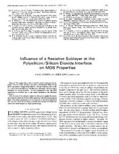
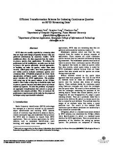
A neuron block is connected to the local port of the router. It consists of a neuron and a synaptic block (Fig. 1). Synaptic block comprises a number of synapses, which are modeled as synaptic weights, and learning data for each synapse. In this work, we take advantage of the STDP method to adapt the synaptic weights. 1) Neuron Different mathematical models of SNNs have been explored over time with different levels of computational efficiency and biological plausibility [19]. Leaky integrate and fire (L&F) and Izhikevich models [20] are two neuron models of SNNs which are used in this work. The L&F model is one of the most widely used models due to its simplicity, but it is limited to a single type of response and not considered for biologically plausible simulations. The Izhikevich model is more complex, but it allows to achieve a large variety of spiking patterns [20].
The SpiNNaker project (Spiking Neural Network Architecture) [12][13] is based on utilizing Multiprocessorbased approaches. The building block of the system comprises 18 ARM968 processor cores. Each building block requires about 1W and can emulate 16,000 Izhikevich neurons with STDP learning. The learning implementation is optimized to minimize the number of computations [27]. The interconnection between each node is handled by a NoC using six links, which is wrapped in a triangular lattice; this lattice is then folded onto a surface of a toroid [17]. SpiNNaker can compute 10^9 neurons in a biological real-time.
2) Synapse Biological synapses connect neurons to each other, providing a mechanism to transmit a signal between neural cells. Variable synaptic strength - the possibility to cause different excitation amplitude at the receiving neuron, is an important property known as synaptic plasticity. Plasticity is modeled in ANN as variable synaptic weight values assigned to the inputs of the neuron model. Learning of neural networks, both biological and artificial, is based on the changing of the synaptic weights. STDP changes weights based on a time difference between incoming and outgoing spikes of a neuron. These spikes are commonly referred to as pre- and postsynaptic, respectively. A popular exponential form of STDP function [8] is as:
EMBRACE (Emulating Biologically InspiRed ArChitectures in hardwarE) utilizes hierarchical (H-NOC) approach, which gives a good trade-off between scalability and power consumption [18]. Like FACETS, EMBRACE is capable of working beyond biological real-time. The H-NOC approach offers a high throughput of spikes per second along with the low power consumption of 13mW for a single cluster facility. However, each module contains a fixed amount of neurons but not an optimized amount. On top of that, EMBRACE has not integrated any learning technique in the network. III.
THE HIERARCHICAL REPRESENTATION OF THE PROPOSED APPROACH
− A exp(−Δ t/ τ + ), if Δ t > 0 Δw = ® + ¯ A− exp(Δ t/ τ − ), if Δ t < 0
A. Networks-on-Chip and Spiking Neural Networks
An NoC consists of an interconnection of many routers to enable a large number of processing elements (PE) to
497
(1)
Fig. 1. A neuron block
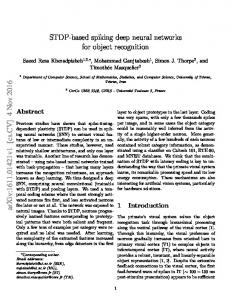
where Δt is timing between spikes; τ determines the time intervals when changes of a weight occur; A constants determine a maximal amount of change. According to the formula, close spikes introduce large impact to the weight while the impact on distant spikes is negligible. As shown in Fig. 2, if a pre-synaptic spike is followed by a post-synaptic one, the synapse will be strengthened. In contrast, if a presynaptic spike arrives after a post-synaptic spike, the synapse is weakened. The amount of change depends exponentially on the distance between spikes and the polarity of change depends on the order in the spike sequence.
spiking activities we can calculate the number of required STDP operations, which is equal to f·S/tstep where f is a spiking frequency. For example, the XOR implementation described at section IV requires 5,400 STDP operations per second for each neuron. The provided number of STDP per second for straightforward implementation is 60,000 operations. This difference gives a space for improvements to reduce the number of STDP blocks about 11 times. We have modeled a functional block diagram of a STDPbased synapse with a shared calculation block among synapses of one neuron as shown in Fig. 1. A neuron block consists of six main components as pre- and post-synaptic tables, timer, STDP controller, STDP calculator, synapse weight table, and neuron cell. The synapse table consists of different partitions, each allocated to one neuron from the previous layer. A partition stores the time stamp of pre- or post-synaptic spikes. There are two principal ways of calculating Equation (1): time steps based and trace function based. In trace based, two decays of STDP equation, corresponding to two parts of Equation (1) are calculated for each synapse. When a pre-synaptic spike occurs, pre-synaptic trace value is updated by some constant (or to a constant) and a value from post-synaptic trace function is used to update the weight and vice-versa. This mechanism is typically implemented in analog designs. The major benefit is that it allows considering all the spike history for STDP updates. However, it requires a little bit more computations per STDP in digital implementation than an alternative scheme which uses time stamps. In this way, when a spike occurs, the time of a spike should be saved and a time stamp from a previous pair of the opposite synaptic type should be taken to calculate �t for Equation (1). Only the closest neighbors are taken into account as they produce the largest impact. Implementation of full spike history would be too costly. We consider the time stamp way due to its simplicity although implementation with trace functions is similar. The synapses weights are stored in the weight table. The STDP calculator performs actual calculation according to a STDP model. The controller performs scheduling of calculations.
Recent biological researches show that STDP depends on the presence of specific neuromodulators like dopamine. This factor can be considered as a control or reward signal that turns STDP from unsupervised into a supervised learning paradigm. A group of works [7],[22],[25] show that controlled reward signal successfully teaches SNN to produce desired output. Thereby, we consider STDP to be a promising rule capable of implementing both unsupervised and reinforcement learning while enlarging the possible application area of the system.
Fig. 2. The STDP principle
Synapses are the dominate components in such systems so that the straight-forward implementation of each synapse with a separate STDP calculation block is extremely expensive even for analog implementations, what imposes a large hardware overhead. With the assumption that one STDP operation (calculation of Equation (1)) is calculated in a single time step, the total number of possible STDP operations per second in the network is S/tstep where S is the number of synapses per neuron and tstep is a simulation step. Assuming the regularity of
498
The reaction of a synaptic block on the spike is shown in Fig. 3. When a new spike arrives at the synapse, the corresponding weight is injected to the neuron cell. In parallel, the STDP process starts, first the time stamp is stored into the corresponding synaptic table and a spike event triggers the STDP control block. Then, the control block fetches postsynaptic time stamps to apply the STDP rule to the newly received pre-synaptic spike with every stored post-synaptic spike, falling into the time window. Sequential calculation is possible due to the sufficient period between spikes and the fact that updated weight is required only by the next spike event on that particular synapse. A similar procedure happens at the post-synaptic spike event. This time, the current post-synaptic time stamp should be saved and compared with every presynaptic spike from each synapse. A pre-synaptic spike event causes the recalculation of the single synaptic weight and a post-synaptic spike leads to the recalculation of all the weights. This is the main reason of using an event buffer in the controller.
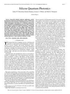
Our analysis shows that the XOR implementation with STDP block shared among the synapses of one neuron provides 1000 STDP operations per second for each neuron. It is less than required, but we assume that a digital implementation allows the synaptic block to work at a higher clock rate than a Neuron Block. For example, the clock rate of the network should be higher to provide a lower spiking delay. With the assumption of having more space for improvements due to higher STDP calculation speed or lower simulation time step, we have modeled a block diagram of STDP synaptic block shared among neurons as shown in Fig. 4. In addition, a possibility to share time stamps for synaptic connections coming from one pre-synaptic neuron is also considered. In the case of a topology with fully connected layers, such an approach allows to reduce the amount of time stamps to S/N, where N is the number of neurons in a cluster. When a spike comes to a shared synapse, only one time stamp is stored and the weighted input is applied to all neurons. When other types of NN topologies are used, additional tables with the connectivity information are required. The behavior of the controller slightly changes after adding sharing modules for pre-synaptic time stamps. A pre-synaptic event then also triggers multiple STDP calculations. The sequence of operations for both synaptic events is similar as depicted in Fig. 5. In case of fully connected layers, the controller can read all the pre- and post-synaptic time stamps sequentially omitting the communication to connectivity tables. C. A clustering Block
As assumed in different works [13], a neuron block is connected to one router. This implies that the area overhead will increase considerably as the number of neurons increases. This is the simplest way of implementing a neural network Fig. 3. Block diagram of reaction on receiving a spike
Fig. 4. A neuron block with shared synapses
499
Read pre-synaptic time stamp
Find post- (pre-) synaptic address
Read post synaptic address from event FIFO
Read post- (pre-) synaptic time stamp
Update the weight
cluster sizes and spiking injection rates. A spiking injection rate refers to the average of spike events that a neuron produces within a simulation time. The simulations are carried out for an XOR problem. The XOR application is a classic benchmark for learning algorithms of artificial neural network training. We use it as an example of classical layered neural network architecture. A. XOR Application
Perform STDP
In the XOR problem, the output 1 should be resulted when the inputs are as {0, 1} or {1, 0}, otherwise the output 0 should be produced [24]–[26]. Similar to [7], [24] for solving this problem, 60 neurons in the input layer, 60 neurons in the hidden layer, and 1 neuron in the output layer are used. As shown in Fig. 7, each layer is fully connected to the next layer meaning that all neurons in the input layer are connected to all neurons in the hidden layer and all neurons in the hidden layer are connected to the single neuron in the output layer. For solving the XOR problem, 121 neurons are needed. For mapping the neurons to an NoC, the first layer of neurons is placed in borderline routers while the hidden layer neurons along with the output neuron are mapped in the central part of the network. We assume that such placement of a first layer should be caused by the presence of continuous external input (e.g. pixel data for video processing tasks). Fig. 8(a) and (b) show the mapping of neurons in 5×5 and 5×4 NoC when 5 and 6 neurons are integrated into one cluster, respectively. The character 0, 1, 2, and 3 stands for non-used, first-layer, hiddenlayer, and output layer, respectively. Out of 60 input neurons, 30 neurons represent logic 0 and other 30 represent logic 1. The input 1 was represented by a Poisson spike train at different frequencies (ranges from 25Hz to 50Hz) and the input 0 was represented by no spiking. Each output spike was rewarded when network was supposed to produce logic 1 output or punished for each spike if desired output was logic 0. Upon iterating this process for few hundred cycles, the network will be capable of producing correct outputs. Fig. 9 shows an output of a SNN trained to perform XOR application. As can be seen in this figure, when the inputs are {0,1} or {1,0}, the output neuron spikes frequently compared with the input {1,1} and {0,0: no spike}.
Read the weight
Fig. 5. Sequence of STDP operations
platform in NoCs but at the cost of considerable area overhead and power consumption. These overheads are paid whereas most of the times the network resources (e.g. buffers and links) are underutilized. In the clustered approach, we connect as many neurons as possible to a router such that to reach the optimal point of resource utilization before approaching the saturation point of the network. This guarantees the maximum throughput and performance with the lowest area overhead and power consumption in this particular aspect. Fig. 6 shows the structure of integrating four neuron blocks.
Fig. 6. A cluster block
IV.
EXPERIMENTAL RESULTS
To evaluate the proposed approach, a simulation platform of combining SNN and mesh-based NoC is developed. RTLlevel of all major components of SNN including cluster blocks (neurons, synapses, and the STDP learning) and NoC modules (routers and links) have been implemented. Each cluster has an additional area overhead of a multiplexer and a de-multiplexer. We have measured latency, throughput, area overhead, and power consumption of the proposed approach for different
Fig. 7. An XOR implementation with 60 neurons in the first layer, 60 neurons in the hidden layer and one neuron in the output layer
500
presented results can be improved by applying multicasting routing scheme, but out of the scope of this work.
(a)
Fig. 10(a) shows the latency results for different spiking injection rates under the XOR benchmark. As demonstrated in this figure, several neurons can be attached to one router with negligible impact on the latency value. With the spike injection rate of 35Hz, the latency value increases from 310 clock cycles with 1/N/C to 757 clock cycles (unit) with 8/N/C. This figure indicates that under higher frequencies, a lower number of neurons can be included into one cluster. For an instance, 6 neurons can be integrated into a cluster when the frequency is 50Hz while 10 neurons can be integrated in a cluster when the frequency is 25Hz without even reaching the saturation point.
(b)
Fig. 8. (a) mapping of neurons in a 5×5 mesh-based NoC with 5/N/C (b) mapping of neurons in a 5×4 mesh-based NoC with 6/N/C
Fig. 10(b) shows the tradeoff between latency, frequency and cluster size. According to this figure, for the frequencies smaller than 35Hz, 10 neurons is the optimal number of neurons per cluster. For the frequencies between 35Hz to 40 Hz, 8 neurons is the best option. The number of neurons per cluster decreases to 6 neurons for the frequencies between 40Hz and 50Hz. This figure can easily show a stable level of latency for different cluster sizes and frequencies. Thereby, according to the application and desired frequency, the optimal cluster size can be found. Fig. 9. An XOR application in SNN
SNN has two phases: Exploration and Exploitation. During the Exploration phase, the network is trained for the particular application; while during the Exploitation phase, the execution is performed according to the learned patterns. B. System Configuration
Each router includes input buffers, a routing unit, an allocator, and a crossbar unit. A router has five input/output ports without using virtual channels. Buffer depth is chosen to be 4. For routing packets, the simple deterministic XY routing algorithm is utilized. It is worth mentioning that performance can be improved by employing adaptive routing algorithms as discussed in different works but this efficiency is out of the concept of this paper. Link width is equal to the packet length that is 16 bits. The packet consists of two fields as source address and destination address. The round robin arbitration is used which provide fairness among requests from different input buffers. As shown in [13] prioritized round-robin arbitration outperforms the FCFS round-robin mechanism. All these optimizations can be done in the network without affecting the general idea of this paper as it is independent of the network configuration such as the underlying routing algorithm and arbitration mechanism. The network size is initially set to 11×11 with 1 neuron per cluster (1/N/C) which is reduced to 3×4 with 10/N/C using the clustering approach.
(a)
(b) Fig. 10. Latency measurement under different frequencies D. Throughput Evaluation
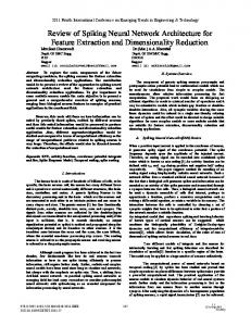
Throughput is also measured for different frequencies and cluster sizes. As shown in Fig. 11(a), throughput increases by integrating more number of neurons per cluster. However, for each frequency there is a breaking point from which throughput starts degrading. This point shows the optimal number of neurons per cluster for that frequency. The tradeoff between
C. Latency Evaluation
Communication latency should be kept as low as possible like in most other applications. One network clock cycle equals to 1/400ms of simulated biological time. The supposed maximum average latency should be 3ms or 1200 cycles. The
501
although they allow presenting a possible value of the proposed approach.
throughput, frequency and number of neurons per cluster is shown in Fig. 11(b). As can be seen from this figure, throughput can be improved by integrating more neurons, but there is a limit for this integration and beyond this limit the network resources overflow and thus throughput decreases. The improvements in throughput mean that network resources are underutilized.
Table 1. Area overhead of the whole platform in �m2 using two models of neuron as L&F and Izhikevich Neuron per Cluster
(a)
Area (�m2) L&F Single Shared
Savings %
Area (�m2) Izhikevich Single Shared
Savings %
1
3,703
3,703
0,0
5,336
5,336
0,0
2
2,739
2,251
17,8
4,458
3,970
10,9
3
2,291
1,666
27,2
3,991
3,367
15,6
4
2,035
1,343
34,0
3,654
2,963
18,9
5
2,016
1,287
36,1
3,702
2,974
19,7
6
1,872
1,116
40,4
3,492
2,737
21,6
7
2,129
1,352
36,5
4,018
3,242
19,3
8
1,899
1,106
41,7
3,626
2,834
21,8
9
2,104
1,301
38,2
4,047
3,244
19,8
10
1,746
0,935
46,4
3,366
2,555
24,1
Table 2. Area overhead (A: nm2) and power consumption (P: �w) of individaul components Router
(b) Fig. 11. Throughput measurement under different frequencies E. Hardware Analysis
In this subsection, the hardware overhead is evaluated under all configurations. The major components of the system as NoC routers, neuron and STDP blocks are synthesized with Synopsys Design Compiler using the UMC 90nm technology with a timing constraint of 500MHz for the system clock and supply voltage of 1.2V.
L&F neuron
Izhikevich neuron
Synaptic
Cluster Overhead (10N/R)
A
13,012
2,647
16,140
10,203
2,055
P
223
102
1,892
375
85
V.
CONCLUSION
In this paper, we presented micro-architectures of SpikeTiming Dependent Plasticity (STDP) based Spiking Neural Network (SNN). A model of sharing synaptic resources for clustered network-on-chip (NoC) is introduced. It improves hardware utilization and cost of STDP computational block. The XOR application is programmed through reinforcement learning technique. An operational regime that guarantees the maximum throughput with the lowest cost is found. Area consumption of the main components of the system is extracted. The results show a significant area reduction.
Two models of neurons have been implemented: L&F and Izhikevich models. In the first configuration, the L&F model of neurons is implemented. The area overhead and power consumption of each individual component is listed in Table 2. As can be seen in this table, the area overhead of the L&F neuron is around six times smaller than a router. The area overhead of the whole platform is listed in Table 1. Results show that by integrating 10 neurons per cluster with a single synaptic block per router, the area overhead of the whole platform decreases by 36% when employing L&F neurons while it decreases by 52% when using Izhikevich neurons. The introduction of shared synaptic resources among neurons provides further improvements of 46% for L&F neurons and 24% for Izhikevich neurons. These results should be considered as raw and not suitable for comparison with other projects
VI.
ACKNOWLEDGEMENT
This work was supported by VINNOVA (Swedish Agency for Innovation Systems) within the CUBRIC and ERoT projects, and academy of Finland.
502
REFERENCES [1]
[2]
[3]
[4] [5]
[6]
[7]
[8]
[9]
[10]
[11]
[12]
[13]
[14]
[15]
H. Markram, W. Maass, and Stephen Grossberg, “Introduction: Spiking Neurons in Neuroscience and Technology.,” Neural Netw., vol. 14, no. 6–7, p. 587, 2001. W. Maass and T. U. Graz, “Networks of Spiking Neurons: The Third Generation of Neural Network Models,” Neural Netw., vol. 10, pp. 1659–1671, 1997. W. Gerstner and W. M. Kistler, Spiking Neuron Models Single Neurons, Populations, Plasticity. Cambridge, U.K., Cambridge University Press, 2002. T. Trappenberg, Fundamentals of Computational Neuroscience, 2nd ed., Oxford, U.K., Oxford University Press, 2010. G. Indiveri, B. Linares-Barrancoet, T.J. Hamilton, et. al., “Neuromorphic Silicon Neuron Circuits,” Front. Neurosci., vol. 5, 2011. P. Livi and G. Indiveri, “A current-mode conductance-based silicon neuron for address-event neuromorphic systems,” in IEEE Int. Symp. on Circuits and Systems, 2009. ISCAS 2009, 2009, pp. 2898–2901. R. V. Florian, “Reinforcement learning through modulation of spiketiming-dependent synaptic plasticity,” Neural Comput., vol. 19, no. 6, pp. 1468–1502, 2007. S. Song, K. D. Miller, and L. F. Abbott, “Competitive Hebbian learning through spike-timing-dependent synaptic plasticity,” Nat. Neurosci., vol. 3, no. 9, pp. 919–926, 2000. H. Anwar, S. M. A. H. Jafri, S. Dytckov, M. Daneshtalab, M. Ebrahimi, A. Hemani, “Exploring Spiking Neural Network on CoarseGrain Reconfigurable Architectures,” in proc. of International Workshop on Manycore Embedded Systems (MES), pp. 64-67, US, 2014. T. Theocharides, G. Link, N. Vijaykrishnan, M. J. Irwin, and V. Srikantam, “A generic reconfigurable neural network architecture implemented as a network on chip,” in IEEE Int. System-On-Chip Conference, 2004, pp. 191–194. R. Emery, A. Yakovlev, and G. Chester, “Connection-centric network for spiking neural networks,” in of the 3rd ACM/IEEE Int. Symp. on Networks-on-Chip, Washington, DC, USA, 2009, pp. 144–152. J. Harkin, F. Morgan, L. McDaid, S. Hall, B. McGinley, and S. Cawley, “A Reconfigurable and Biologically Inspired Paradigm for Computation Using Network-On-Chip and Spiking Neural Networks,” Int. J. Reconfigurable Comput., vol. 2009, pp. 1–13, 2009. S. Carrillo, J. Harkin, L. McDaid, S. Pande, S. Cawley, B. McGinley, and F. Morgan, “Advancing interconnect density for spiking neural network hardware implementations using traffic-aware adaptive network-on-chip routers,” Neural Networks Off. J. Int. Neural Netw. Soc., vol. 33, pp. 42–57, 2012. M. Palesi and M. Daneshtalab (Eds.), “Routing Algorithms in Networks-on-Chip, ” Springer 2014.
[16]
[17]
[18]
[19] [20] [21] [22]
[23]
[24]
[25]
[26]
[27]
[28]
503
S. Choudhary, S. Sloan, S. Fok, A. Neckar, E. Trautmann, P. Gao, T. Stewart, C. Eliasmith, and K. Boahen, “Silicon Neurons That Compute,” in Artificial Neural Networks and Machine Learning – ICANN 2012, 2012, pp. 121–128. J. Schemmel, D. Bru derle, A. Gru bl, M. Hock, K. Meier, and S. Millner, “A wafer-scale neuromorphic hardware system for large-scale neural modeling,” in IEEE Int. Symp. on Circuits and Systems (ISCAS), 2010, pp. 1947–1950. K. Dugan, J. Reeve, A. Brown, and S. Furber, “Interconnection system for the spiNNaker biologically inspired multi-computer,” IET Comput. Digit. Tech., vol. 7, no. 3, 2013. S. Carrillo, J. G. Harkin, L. J. McDaid, S. Pande, S. Cawley, B. McGinley, and F. Morgan, “Hierarchical Network-on-Chip and Traffic Compression for Spiking Neural Network Implementations,” in ACM/IEEE International Symposium on Networks-on-Chip (NoC), 2012, pp. 83–90. E. M. Izhikevich, “Which model to use for cortical spiking neurons?,” IEEE Trans. Neural Networks, vol. 15, no. 5, pp. 1063–1070, 2004. E. M. Izhikevich, “Simple model of spiking neurons,” IEEE Trans. Neural Networks, vol. 14, no. 6, pp. 1569–1572, 2003. J. Sjöström and W. Gerstner, “Spike-timing dependent plasticity,” Scholarpedia, vol. 5, no. 2, p. 1362, 2010. E. M. Izhikevich, “Solving the Distal Reward Problem through Linkage of STDP and Dopamine Signaling,” Cereb. Cortex, vol. 17, no. 10, pp. 2443–2452, 2007. R. Legenstein, D. Pecevski, and W. Maass, “A learning theory for reward-modulated spike-timing-dependent plasticity with application to biofeedback,” PLoS Comput. Biol., vol. 4, no. 10, Oct. 2008. H. S. Seung, “Learning in spiking neural networks by reinforcement of stochastic synaptic transmission,” Neuron, vol. 40, no. 6, pp. 1063– 1073, 2003. X. Xie and H. S. Seung, “Learning in neural networks by reinforcement of irregular spiking,” Phys. Rev. E Stat. Nonlin. Soft Matter Phys., no. 69, pp. 1–10, 2004. S. Hong, L. Ning, L. Xiaoping, and W. Qian, “A cooperative method for supervised learning in Spiking neural networks,” in 2010 14th Int. Conf. on Computer Supported Cooperative Work in Design (CSCWD), 2010, pp. 22–26. J. Xin, A. Rast, F. Galluppi, S. Davies, S. Furber, "Implementing spike-timing-dependent plasticity on SpiNNaker neuromorphic hardware," The 2010 Int. Joint Conf. on Neural Networks (IJCNN), vol., no., pp.1,8, 18-23 July 2010 J. Arthur, K. Boahen, “Learning in Silicon: Timing is Everything,” Advances in Neural Information Processing Systems 18, MIT Press, pp 75-82, 2006.