Global Grid Planner. (Kinematics). Emergency Stop Plan. Precomputed. Motion Tree. Local Runtime Planner. (Dynamics). Fail. Fail. Up-to-date Environment.
Efficient Two-phase 3D Motion Planning for Small Fixed-wing UAVs Myung Hwangbo
James Kuffner
Takeo Kanade
The Robotics Institute Carnegie Mellon University 5000 Forbes Avenue, Pittsburgh, PA, 15213, USA {myung, kuffner, tk}@cs.cmu.edu
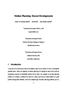
Abstract— We present a novel two-phase approach to motion planning for small fixed-wing Unmanned Aerial Vehicles(UAVs) navigating in complex 3D air slalom environments. A coarse global planner first computes a kinematically feasible obstaclefree path in a discretized 3D workspace which roughly satisfies the kinematic constraints of the UAV. Given a coarse global path, a fine local motion planner is used to compute a more accurate trajectory for the UAV at a higher level of detail. The local planner is iterated as the UAV traverses and refines the global path as needed up to its planning horizon. We also introduce a new planning heuristic for fixed-wing UAVs based on 2D Dubins curves, along with precomputed sets of motion primitives derived from the UAV dynamics model in order to achieve high efficiency. 3D air slalom scenario for a small fixed-wing UAV: The airplane is asked to pass through all the gates in order autonomously. Fig. 1.
I. I NTRODUCTION Recent advances in sensor devices, communications, and battery technology have made fixed-wing Unmanned Aerial Vehicles (UAVs) smaller in size and cost-competitive. Smallsize UAVs are becoming an increasingly attractive solution for a variety of scientific, civil, and military applications. While some autonomous UAVs are employed successfully in security and military services, urban applications such as infrastructure monitoring demands small or even micro UAVs to maneuver within complex obstacle-filled environments. Operating a UAV under these conditions poses a number of difficult challenges. Environments cluttered with buildings and overhangs require high maneuverability and fast adaptation to dynamic and unknown obstacles. Fixed-wing UAVs require a relatively high minimum forward velocity to maintain lift. Thus, in order to respond quickly to unknown obstacles, high-performance real-time motion planning that respects the complex dynamic constraints of the UAV must be accomplished without any significant delays. We have been developing an Unmanned Aerial vehicle System (UAS) designed to accomplish a 3D air slalom scenario shown in Figure 1. In this scenario, several labeled gates are arranged in the environment. The gates are placed either on the ground or in the air, and the UAVs are instructed to pass through each of the gates sequentially in the order specified. Although autonomously computing the UAV trajectory to accomplish this task is the focus of this paper, many other system components comprise the complete solution. The UAV maintains up-to-date perception of the environment and its
own state through onboard cameras, IMU and GPS. Each slalom gate requires the UAV to pass through the target hoop with the correct 3D position as well as aligned pitch and yaw angles. Our goal is to build a real-time motion planner for 3D slalom scenarios that allow the UAV to operate reliably in the presence of fixed, moving or unknown obstacles. This paper presents a novel two-phase approach to motion planning for the 3D air slalom scenario. First, a coarse global planner computes a kinematically feasible obstacle-free path in a discretized 3D workspace which roughly satisfies the kinematic constraints of the UAV. Then, a fine local motion planner computes a more accurate trajectory for the UAV at a higher level of detail. The local planner is iterated as the UAV traverses and refines the global path as needed up to its planning horizon. In order to achieve real-time performance, we have developed new planning heuristics for fixed-wing UAVs, and utilize precomputed sets of motion primitives derived from the UAV dynamics model. The result is an efficient planner that satisfies both the kinematic and dynamic constraints of the UAV while navigating in complex partiallyknown 3D environments. II. R ELATED W ORK There have been a number of research efforts in both the robotics and computer animation literature related to planning 2D or 3D trajectories for guiding aircraft in known or unknown
Start & Goal Configuration
Global Grid Planner (Kinematics)
Waypoints
Environment changed?
Fail Fixed and known Environment
YES
NO
Waypoint Controller UAV
Subgoal
Local Runtime Planner (Dynamics)
Fail
Emergency Stop Plan
Precomputed Motion Tree
Up‐to‐date Environment (small, moving, and unknown obstacles)
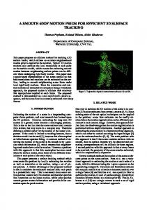
Fig. 2. Overview of overall planning architecture: The coarse global planning and the fine local planning compensate each other.
environments. Previous research for UAVs in robotics has primarily explored vision-based navigation for UAVs [1], or basic obstacle avoidance during flight [2]. A 3D local trajectory planner has been presented in [3] for autonomous navigation with a predefined global path. They also utilize a two-stage strategy consisting of a decision mode and a trace mode. The controller design in trace mode is heuristic, so applying the method to other dynamic systems can sometimes be difficult. A more complicated nonlinear and high-dimensional hybrid system control architecture [4], [5] was developed for an autonomous helicopter. This planner utilized libraries of trim trajectories, along with an efficient online replanning framework based on Rapidly-exploring Random Trees (RRTs) [6], which has been broadly used to plan motions for dynamic systems subject to dynamic constraints. In computer animation, reactive steering behaviors for flocking, grouping and avoiding obstacles are presented in [7]. Although highly efficient, these techniques only use local information. An autonomous vehicle animation and planning system using online search and trajectory precomputation was developed in [8]. Precomputed search trees were also used to assemble planned sequences of human motion for animated characters navigating in complex virtual environments [9]. In our work, we focus on developing an efficient motion planner for solving the 3D air slalom task, with particular attention to computing global paths that satisfy both the kinematic and dynamic constraints of the UAV. The rest of the paper is organized as follows: an overview of our two-phase motion planning method is discussed in Section III; the details for the global grid planner and the local runtime planner with motion primitives are described in Section V and Section IV respectively; experimental results in simulation is presented in Section VI. III. T WO - PHASE MOTION PLANNING According to the original scheme of two-phase planner [10] first a collision-free path as well as a robot workspace are given as starting points. Then its final path is obtained after refining it by optimizing an initial feasible path with respect
to a desired criteria. This strategy is very useful to cover a large UAV workspace and to make overall planning run fast. Here brief descriptions are given for the global planner and the local runtime planner to understand overall architecture of our planner design in Fig. 2. In our planning architecture we first plan an obstacle-free path in a discretized workspace. The size of discretization and possible connections between nodes in the workspace are elaborately designed from given kinematic constraints of a UAV. So the output of the global planning never violates its kinematic constraints. Following the global path is easily achievable with a general waypoint controller because waypoints are kinematically feasible. Moreover the use of A* in the global grid planner makes a planned path never trapped in a local minimum and always guaranteed to be optimal in terms of its cost. This is a good news to the local planner because it is unprotected from local minima due to limited path planning horizon. So we select an appropriate point on the global path as a subgoal for the local planner. The local planner compensates the drawbacks of the global planner: coarse discretization of configuration space(C-space), inability to avoid small or moving obstacles. With densely sampled motion primitives it can connect two configurations in a finer level. But its planning horizon is limited by the available computational power. The local planner is invoked when partial planning is needed over short segments of the global path at a time. That happens when the environment changes after the global plan has been made or small obstacles appear. In the global planning we tend to neglect small obstacles because the cell size is relatively large. (It sets to two thirds of UAV’s minimum turning radius) In case either planner fails to find a path for any reason, emergency stop planning is called up immediately to escape a critical situation. It is a backup plan to move the airplane to a safe region that has the lowest probability of crashing. This plan should run all the time at the background whenever airplane state or the environment is updated. IV. G LOBAL G RID P LANNER WITH F EASIBLE C ONNECTIONS One of most popular techniques in robot navigation is searching a solution which connects starting and goal configurations from a discretized grid representation of an environment [11]. The global planner for a UAV is also working on 3D grids but with different node definition from a voxel. By differing feasible connections from a grid cell to neighboring cells depending on its parent we can make a kinematically feasible path from node connections. A. Node defintion and node connections A node used for the global planning is defined with its position on 3D grids as well as the direction from its parent(parent connection). The parent connection has 26 possible ways and can be considered as a single number encoding coarsely discretized yaw angle(φ) and pitch angle(θ) of an airplane. In other words the node corresponds to a point in the
Top view R min
P
C
C P
(a)
C
C
P
P
(c)
(f)
(b)
C
P
(d)
(a)
(b)
Generation of motion primitives: (a) A reachable set by a simple PD waypoint controller (b) Collection of a set of motion primitives is stored in a discretized pitch(φ) and roll angle(ψ) space. Fig. 4.
(e)
Fig. 3. Node definition and connections in the global grid planner: A node is defined with its position in 3D grids and parent connection. It corresponds to one cell in the discretized C-space (x, y, z, θ, φ). Node connections reflects the kinematic constraints Rh,min and µmax of an airplane. The horizontal forward-only connections in (a),(b) means a minimum forwarding velocity of the airplane. The airplane’s vertical maneuverability decides one of the vertical connections in (c),(d), and (e).
discretized C-space (x, y, z, φ, θ). Note that the roll angle(ψ) is excluded from the C-space since there is no way to take it into account here. Node connection can be defined arbitrarily but we can elaborate it to reflect airplane’s kinematic constraints. The horizontal forward-only connections is defined as a set of connections of which the angle with a parent connection is smaller than 90 degrees and a parent connection moves horizontally as illustrated in Fig.3(a)(b). This connection is physically reasonable since an airplane moves with the minimum forwarding velocity. For node connection in a vertical way several possible choices are shown in Fig.3(c)(d)(e). The choice depends on airplane’s vertical maneuverability. For example, vertical forward connection in Fig.3(c) can perform a looping feat. B. Setting grid cell size The main kinematic constraints on a UAV we consider in the global planning are the minimum horizontal turning radius(Rh,min ) and maximum climbing angle(µmax ). Fig.3(f) shows that repeating this horizontal forward-only connections generates a circle of which minimum radius is one and half times the grid size. Therefore, we can set the grid size in x(Sx ) and y(Sy ) to two thirds of Rh,min . The grid size in z Sz is decided by both the maximum climbing angle µmax and choice of vertical node connections. For example in case µmax = 45◦ , we can choose {Fig.3(d), Sz = Sx } or {Fig.3(e), Sz = 2 Sx }. C. Precomputing optimal cost-to-go for a heuristic In a search graph of the global grid planner the Euclidean distance no longer a good heuristic because the node has the
direction as well as the position in 3D. Therefore, the optimal cost-to-go can be computed over some region around a origin(in our case 9x9x9 grid). When a heuristic is needed at a current node, the precomputed region moves to a current node. In case a goal is outside of that region, first find a node which is the closest to a goal with the same parent connection in that region and then add the Euclidean distance from a goal to the node to the precomputed cost of that node. Precomputation for a better heuristic helps reduce the number of nodes visited in search. Due to the symmetries in 3D one of octants of parent connections is enough: (1,0,0), (1,1,0), (1,0,1), (1,1,1), and (0,0,1) in case the first octant is used. V. L OCAL RUNTIME P LANNING FROM M OTION P RIMITIVES While the global planner covers a large workspace with a coarsely discretized C-space, the local planner has the ability to connect two configurations of fine resolution with densely sampled motion primitives. This online planner is supposed to refine a global path locally, to response unexpected obstacles and to avoid small obstacles which are ignored in the global planning. The C-space is the same as that of the global planning C = (x, y, z, φ, θ). The rolling angle ψ is ignored as well. An local obstacle-free path is a solution of a search graph which is connected precomputed motion primitives on the discretized C-space of the airplane. The use of a good and efficient heuristic is essential especially for a greedy search like best-first which we use. Two new heuristics are proposed in different C-spaces. A. Generating motion primitives Motion primitives need to capture the relevant dynamic characteristics of an airplane in planning. More complex behaviors can be created via the interconnection of motion primitives. A new state xk+1 is generated by applying uk , a grid of waypoints in Fig.5 to a discretized dynamic system fd
waypoints
xI
xG
xI
C
xG
S
C C
C
Motion primitives
(a)
C
(b)
xI
Fig. 5. Control-based action sampling: A grid of waypoints ahead of the aircraft are inputs({uk }) to the discretized dynamic system fd . A set of segments of motion induced by a waypoint controller are saved in a look-up-table with the ending states and a couple of middle points to detect collision.
xI
xG xG
from a starting state xk . xk+1 = fd (xk , uk )
(c)
(d)
(1)
The look-up-table saves motion primitives corresponding to the discretized airplane’s roll and pitch angles. To reduce memory size for the table each primitive only has starting and ending states and a couple of middle point locations for collision checking. Fig.4 shows an explored motion tree for sampling and some of the saved motion primitives. B. Forward dynamic programming: best-first search Several forward search algorithms differ by a different sorting method of the queue. The rationale for choosing the best-first method is that the branching factor at each node is quite big (in our case 40 on average). and a subgoal needs up to 15 steps of primitive motions to be accomplished. The exhaustive search like breadth-first makes a search tree grow exponentially with respect to depth level. For best-first search, the priority queue is sorted according to an optimal cost-to-go estimated by a heuristic. The solutions obtained in this way are not necessarily optimal. But in many cases, far fewer nodes are explored, which results in much faster running times. Though the search is too greedy, we compensate for penalty with enhanced heuristic h1 , h2 described in the next part. The search starts by building a tree and assigning a current airplane state as its root. By applying all motion primitives available at a current state from the look-up-table, a new set of nodes corresponding to unvisited states are generated at the next depth level. If any point on a motion primitive is in any obstacle region, that node is discarded from a tree. The costs to a goal for all new nodes are computed from the heuristic. The motion node closest to the goal is expanded again until the state in the goal region is found. C. Two heuristics based on 2D Dubins curve We propose two new heuristics to estimate optimal cost to a goal. Dubins curves [12] for a search heuristic are very useful
Fig. 6. Two heuristics to estimate the optimal cost-to-go: (c) C-space
(x, y, z, φ, θ) for h2 (d) C-space (x, y, z, θ) for h1 . (a)(b) shows examples of 2D Dubins curve which is the shortest path between xI , xG ∈ SE(3)
since the limits on the motion of the Dubins car are very close to those of the airplane except for the dimensionality of the C-space. Dubins curves are the shortest length path between two configurations xI , xG ∈ SE(2) which is a combination of no more than three of motion primitives which are straight and circular paths as shown in Fig.6(a)(b). This path length is obtainable without expensive computation based on phase partitions [13]. In practice, especially for a sampling-based motion planning, a proper goal region needs to be set around a goal configuration when a heuristic is computed because the 2D Dubins metric has discontinuities in its C-space. (i) C = {x, y, z, θ} First consider one simple kinematic equation [14] for an fixed-wing airplane. It can be used as a pseudo-metric based on the maximum yaw rate(uw ) and altitude changes(uz ) of the airplane. For the fixed inputs a helical path like Fig.6(d) is the same as the distance function. Here the C-space is in (x, y, z, θ). The pitch angle φ is not involved in the C-space. x˙ = cos θ,
y˙ = sin θ,
θ˙ = uw ,
z˙ = uz
(2)
The length of path from Eq.(2) can be approximated by the following simple way: First compute 2D Dubins metric `h,Dubins on the horizontal plane in a reduced C-space (x, y, θ). And keep adding the length of a circle with minimum radius Rh,min until the enough horizontal traveling distance to satisfy a maximum climbing angle µmax . Start with h1 (xI , xG ) ← `h,Dubins and ∆z = zI − zG
h1 ← h1 + 2πRh,min until |∆z/h1 | < sin(µmax )
TABLE I U SE OF DIFFERENT HEURISTICS IN Iteration No. of nodes visited No. of nodes revisited Avg. runtime(sec)
THE GLOBAL GRID PLANNING
Euclidean dist 65504 96230 483562 0.475
Precomputed 12038 23142 83207 0.135
h∗
(A*)
G2 G2
Speed-up 5.44 4.15 5.81 3.50
G1 G1
Note that optimal cost-to-go h∗ is precomputed over 9x9x9 grid size. Results are averaged over 100 runs with randomly selected initial and goal nodes. The size of 3D grid world is 50 x 50 x 50 and the same obstacle environment in Fig. 5 is used.
(ii) C = {x, y, z, φ, θ} The pitch angle(φ) is added to Cspace. As in Fig. 6(c) two 2D Dubins curves are considered along two projection planes. One is for horizontal motion to align yaw angle and the other is for vertical motion to align pitch angle. The combination of two shortest path lengths w.r.t. minimum turning radii, Rh,min and Rv,min , is defined as a distance function between two configurations. The average of two path lengths are used here. h2 (xI , xG ) =
1 (`h,Dubins + `v,Dubins ) 2
(3)
We can not claim that both are optimistic(admissible) because the dimensions of C-spaces of h1 and h2 are less than that of the actual C-space of the airplane. But they provides the search fairly good information how close to a goal. The difference of two heuristics h1 and h2 become apparent when a motion node is near the goal with a wrong pitch angle. The h2 prevents those kind of nodes from being visited in best-first search. VI. S IMULATION R ESULTS The scaled-down version of a low fidelity F16 dynamic model [15] is used for simulation. To fit it with general kinematic and dynamic ranges of small fixed wing UAVs, all the units are scaled down by 100. The aircraft speed v is set to 2m/s and the minimum horizontal and vertical turning radii Rh,min , Rv,min are both measured 20m. In the global grid planner the cell size Sx and Sy are set to 13.3m, two-thirds of Rh,min . And Sz is set the same as Sx from the max. climbing angle µmax = 45◦ . For node connections we use the horizontal forward-only node connection at Fig.3(a)(b), and the successive vertical movement at Fig.3(d). But straight upward or downward motion is prohibited. Fig 7 shows how the path plan changes when a goal has either opposite direction or a different location. The planned paths require enough space in front to turn around or go up and down since the node at each grid cell propagates only to its neighborhood in a forward direction. Table-I shows the speed-up in global grid search from the precomputation for optimal cost-to-go h∗ . The cost is precomputed up to 9x9x9 grid cells by running Dijkstra algorithm. Fig.9 shows the basic performance of the local discrete dynamic planner. The heuristic function h2 in Eq.3 is used
S S
(a)
(b)
G2 G2
G1
G1
S
S
(c)
(d)
Fig. 7. Examples of obstacle-free paths from the global grid planner:
There are two goal gates for a UAV to pass in order. The arrow at the gate indicates the goal orientation. The first goal G1 has an opposite orientation in each column and the second goal G2 is placed a different location in each row. The horizontal forward-only node connection in Fig.3(a)(b) is allowed. For vertical node connections the successive vertical movement is allowed but straight upward or downward is prohibited as in Fig.3(d).
here. At each node 41 motion primitives which correspond to a current vehicle state are expanded from the look-up-table. The small number of expanded nodes during search verifies the effectiveness of the heuristic function we employed. More node expansions happen near the goal since those have a small cost in best-first search and need finer adjustment to get in the goal region due to discretization of motion. A* will generate more nodes in the middle of the way to find a optimal path. Fig.8 shows how the local planner works in the presence of obstacles. The use of a different heuristic function generates a different type of motion behavior in the best-first search. From Fig.6(b), a helical motion corresponding to the heuristic h1 needs to perform a turn-around motion first to move vertically. The climbing slope is set to 0.2 (10m traveling distance requires to 2m vertical). The vehicle in Fig.8(a) avoids the front obstacle with a horizontal motion since the traveling distance is not enough to return to the same altitude after vertical movement. In Fig.8(b) the heuristic h2 guides the vehicle to move vertically to follow a shorter path in terms of its heuristic. The performance of the two-phase planner in the 3D air slalom scenario is shown in Fig.10. From the planner architecture in Fig.2 when the vehicle is at the initial position, the global path(a dotted line) is first planned based on known obstacles(solid boxes). Before a new obstacle(spheres) is de-
(a)
(b)
Examples of the local path planner in absence of obstacles: The best-first search explores motion nodes toward a goal in a greedy way. The heuristic function h2 based on the 2D Dubins curves guides the nodes efficiently to a goal state. All motion primitives queued in the search tree are also displayed to see how much nodes has been expanded until it reaches a goal. The goal has a different yaw angle in each figure. Fig. 9.
(c)
(d)
Fig. 8. Obstacle avoidance with the local path planner using motion
primitives: Two different heuristic functions h1 , h2 are applied to the same environment in (a) with h1 and (b) with h2 . In (a) the airplane prefers moving horizontally since h1 needs a helical motion to fly upward. On the other hand the airplane moves vertically to avoid an obstacle in (b). In (d) the goal is too close for the airplane to have a goal angle so the airplane moves around via 270◦ turning.
and control systems and demonstrating our result on the actual small fixed-wing UAV platform. R EFERENCES
tected at the point A or C, a waypoint controller follows the global path. The subgoal B or D is selected from the global path so that the local planner plans a path to avoid new obstacles. VII. S UMMARY AND F UTURE W ORK We have presented an efficient motion planning method for small fixed-wing UAVs in complex 3D environments. Twophase planning (global and local planners) are used to plan motions in large cluttered areas while respecting the UAV’s kinematic and dynamic constraints. By adding directionality to the conventional 3D grid cell, a search tree in 3D space can be constructed only with feasible node connections which take into account for UAV’s forward-only motion constraints. The path found in this search tree satisfies two important kinematic constraints of the UAV: the minimum turning radius and the maximum climbing angle. We also proposed two new heuristics to estimate the optimal cost-to-go during local planning, involving an approximation of the shortest path of the UAV in 3D by projection of the full configuration space into two planes which enable the application of Dubins curves. Utilizing precomputed sets of available motion primitives for discretized vehicle states, a best-first search local planner finds obstacle-free paths that satisfies the dynamic constraints. We have demonstrated the efficiency and effectiveness of the twophase planner in complex simulated 3D air slalom scenarios. Our future work involves integrating the perception, planning,
[1] B. Sinopoli, M. Micheli, G. Donata, and T. Koo, “Vision based navigation for an unmanned aerial vehicle,” in Proc. IEEE Int’l Conf. on Robotics and Automation, 2001. [2] R. Zapata and P. Lepinay, “Flying amoong obstacles,” in European Workshop on Advanced Mobile Robots, 1999. [3] J. Sasiadek and I. Duleba, “3d local trajectory planner for uav,” Journal Journal of Intelligent and Robotic Systems, vol. 29, no. 2, pp. 191–210, Oct. 2000. [4] E. Frazzoli, M. Dahleh, and E. Feron, “A hybrid control architecture for aggressive maneuvering of autonomous helicopters,” 1999. [5] ——, “Real-time motion planning for agile autonomous vehicles,” AIAA Journal of Guidance, Control, and Dynamics, vol. 25, no. 1, pp. 116– 129, 2002. [6] S. LaValle and J. Kuffner, “Randomized kinodynamic planning,” International Journal of Robotics Research, vol. 20, no. 5, pp. 378–400, May 2001. [7] C. Reynolds, “Steering behaviors for autonomous characters,” in Game Developers Conference, 1999. [8] J. Go, T. D. Vu, and J. Kuffner, “Autonomous behaviors for interactive vehicle animations,” Graphics Models, vol. 68, no. 2, pp. 90–112, 2006. [9] M. Lau and J. Kuffner, “Precomputed search trees: Planning for interactive goal-driven animation,” in ACM SIGGRAPH / Eurographics Symposium on Computer Animation, 2006. [10] J. E. Bobrow, “Optimal robot path planning using the minimum-time criterion,” IEEE Trans. on Robotics and Automation, vol. 4, no. 4, pp. 443–450, 1988. [11] J. C. Latombe, Robot Motion Planning. Boston, MA: Kluwer Academic Publishers, 1991. [12] L. E. Dubins, “On curves of minimal length with a constraint on average curvature, and with prescribed initial and terminal positions and tangents,” American Journal of Mathematics, vol. 79, pp. 497–516, 1957. [13] X.-N. Bui, P. Soueres, J.-D. Boissonnat, and J.-P. Laumond, “Shortest path synthesis for dubins nonholonomic robot,” in Proc. IEEE Int’l Conf. on Robotics and Automation, 1994. [14] S. M. LaValle, Planning Algorithms. Cambridge University Press (also available at http://msl.cs.uiuc.edu/planning/), 2006.
D
G2
C G1
B
S
A
G2
S
D
A
G1
C
A example of two-phase planner which is combined with global grid planner and local discrete dynamic planner: The solid boxes are fixed and known obstacles. The spheres are unknown and become detected when the vehicle arrives at points A and C. A dotted line is a path from the global grid planner. In AB and CD the local planner generates new obstacle-free paths that safisfy the vehicle dynamics. Actual vehicle path is drawn by a solid line. Fig. 10.
[15] R. S. Russell, Nonlinear F-16 Simulation using Simulink and Matlab. http://www.aem.umn.edu/people/faculty/balas/darpasec/SEC.Software.html, 2003.