hungry and incorporation of such an algorithm as part of a crypto accelerator presents ... As far as number of clock cycles to compute inversion are concerned, ..... section, we try to address this issue and determine the factors that are decisive ...
Efficient Unified Montgomery Inversion with Multibit Shifting E. Sava¸s1 , M. Naseer1 , A. A-A. Gutub2 , and C ¸ . K. Ko¸c3 1
Faculty of Engineering & Natural Sciences Sabanci University Istanbul, Turkey TR-34956 2
Computer Engineering King Fahd University of Petroleum & Minerals Dhahran 31261, Saudi Arabia 3
Electrical & Computer Engineering Oregon State University Corvallis, Oregon 97331
Abstract Computation of multiplicative inverses in finite fields GF (p) and GF (2n ) is the most time consuming operation in elliptic curve cryptography especially when affine coordinates are used. Since the existing algorithms based on extended Euclidean algorithm do not permit a fast software implementation, projective coordinates, which eliminate almost all of the inversion operations from the curve arithmetic, are preferred. In this paper, we demonstrated that affine coordinates implementation provides a comparable speed to that of projective coordinates with careful hardware realization of existing algorithms for calculating inverses in both fields without utilizing special moduli or irreducible polynomials. We presented two inversion algorithms for binary extension and prime fields, which are slightly modified versions of the Montgomery inversion algorithm. The similarity of the two algorithms allows the design of a single unified hardware architecture that performs the computation of inversion in both fields. We also proposed a hardware structure where the field elements are represented using a multi-word format. This feature allows a scalable architecture able to operate in a broad range of precision, which has certain advantages in cryptographic applications. In addition, we included statistical comparison of four inversion algorithms in order to help choose the best one amongst them for implementation onto hardware.
1
Introduction
The basic arithmetic operations (i.e. addition, multiplication, and inversion) in prime and binary extension fields, GF (p) and GF (2n ), have several applications in cryptography, such as RSA algorithm, Diffie-Hellman key exchange algorithm [2], the Government Digital Signature Standard [3] and also elliptic curve cryptography [4, 5]. Recently, speeding up inversion operations in both fields has been gaining attention since inversion is the most time consuming operation in elliptic curve cryptographic algorithms when affine coordinates are selected [6, 7, 8, 9, 10, 11].
1
Currently, most of the elliptic curves that are employed in cryptographic applications are defined over prime GF (p) and binary extension GF (2n ) fields. In [12], a scalable and unified multiplier architecture for both fields is proposed and it has been shown that it is possible to design a multiplier with an insignificant increase in chip area (about 2.8%) and no increase in time delay since the Montgomery multiplication algorithms for both fields are almost identical, except that basic addition operation of the corresponding fields. In this paper, we give and analyse multiplicative inversion algorithms for GF (p) and GF (2n ), which allow very fast and area-efficient hardware implementations. The algorithms are based on the Montgomery inversion algorithms given in [6]. Another variation of the Montgomery inversion algorithm is proposed in [8], which provides a very fast implementation of multiplicative inverse in GF (p). This algorithm takes the advantage of a multiplication unit, which already exists in most of the modern multipurpose microprocessors. Implementations of this algorithm are generally areahungry and incorporation of such an algorithm as part of a crypto accelerator presents difficulties. Accordingly it is not suited to our needs. In a recently published technical report [13], two similar algorithms for direct calculation of modular division in GF (p) and GF (2n ) have been proposed. Based on binary extended Euclidean algorithm [1] (attributed to M. Penk), [13] eliminates the correction phase of the Montgomery inversion algorithm by introducing extra add-and-shift operations in the while loop of the algorithm. However, performing these extra operations within the loop maintains the cost similar to performing them in Phase II. Furthermore, this approach does not run the algorithm in different modes as described in [9] in order to calculate different inverses, which prove to be useful in elliptic curve cryptography. Two algorithms proposed separately for fast calculation of inversion operations of GF (p) and GF (2n ) in [14] and [15] respectively, do not allow a unified design. A more recent effort [16] presents an efficient inversion algorithm that computes a direct inversion and decreases the number of additions at the expense of introducing, on average, more stand-alone1 shift operations. As far as number of clock cycles to compute inversion are concerned, shift operations are as costly as addition operations in a scalable implementation since these shift operations are performed in more than one cycle. In addition, the algorithm in [16] applies the logical OR operation on the entire bits of an integer. In cryptographic applications where the integers are large, this OR operation may have an adverse effect on the scalability and critical path delay. Therefore, we use variants of Montgomery inversion algorithm in our work that we believe are more suitable for hardware implementation. In this paper, we present similar algorithms based on the Montgomery inversion algorithm suitable for scalable and unified hardware implementations. In Section 2, the definition for the original Montgomery inversion algorithm is given and the three basic theorems about the algorithm are included. The Montgomery inversion algorithm for the binary extension field GF (2n ) is described and three similar theorems are proven in Section 3. In Section 4, a variant of the original algorithm for GF (p) is presented, which provides better performance in hardware. In Section 5, the complexity issues of the inversion operation are addressed by providing experimental results and forecasts. In addition, two algorithms for decreasing the number of shift operations are presented in Section 5. Section 6 compares the proposed algorithm against the other prevalent algorithms from the hardware implementation point of view. Section 7 addresses the key concepts of the implemented hardware architecture such as scalability and unified design. Implementation results are given in Section 8. The paper concludes with a summary of contributions and the results which 1
Note that the shift operations following subtraction operations in the original Montgomery inversion algorithm must not be counted separately as done in [16]
2
provide a novel perspective in hardware realization of elliptic curve cryptography accelerators.
2
The Original Montgomery Inversion Algorithm
The Montgomery inversion algorithm as defined in [6] computes b = a−1 2n
(mod p) ,
(1)
given a < p, where p is a prime number and n = �log2 p�. The algorithm consists of two phases: the output of Phase I is the integer r such that r = a−1 2k (mod p), where n ≤ k ≤ 2n and Phase II is a correction step and can be modified as shown in [9] in order to calculate a slightly different inverse that can more precisely be called Montgomery inverse: b = M onInv(a2n ) = a−1 2n
(mod p) ,
(2)
This new definition is more suitable since it takes an integer in so-called Montgomery domain and yields its multiplicative inverse, again in Montgomery domain. Below, we give the original Montgomery inversion algorithm for completeness; however the new algorithms in subsequent sections will compute the Montgomery inverse of an integer as defined in (2). Algorithm A Phase I Input: a ∈ [1, p − 1] and p Output:r ∈ [1, p − 1] and k, where r = a−1 2k and n ≤ k ≤ 2n 1: 2: 3: 4: 5: 6: 7: 8: 9: 10:
(mod p)
u := p, v := a, r := 0, and s := 1 k := 0 while (v > 0) if u is even then u := u/2, s := 2s else if v is even then v := v/2, r := 2r else if u > v then u := (u − v)/2, r := r + s, s := 2s else v := (v − u)/2, s := s + r, r := 2r k := k + 1 if r ≥ p then r := r − p return r := p − r and k
Phase II Input: r ∈ [1, p − 1], p, and k from Phase I Output: b ∈ [1, p − 1], where b = a−1 2n (mod p) 11: for i = 1 to k − n do 12: if r is even then r := r/2 13: else r := (r + p)/2 14: return b := r There are three important theorems about the algorithm, which have already been proven in [6]. 3
Theorem 1 If p > a > 0, then the intermediate values r, s, u, and v in the Montgomery inversion algorithm are always in the range [1, 2p − 1]. Theorem 2 If a and p are relatively prime, p is odd, and p > a > 0, then the number of iterations in the first phase of Montgomery inversion algorithm is at least n and at most 2n, where n is the number of bits in p. Theorem 3 If p and a are relatively prime, p is odd, and p > a > 0, then Phase I of Montgomery inversion algorithm returns a−1 2k (mod p). We will include and prove analogous theorems for Montgomery inversion algorithm for binary extension fields GF (2n ) in the next section.
3
The Montgomery Inversion Algorithm for GF (2n)
Let
p(x) = xn + pn−1 xn−1 + pn−2xn−2 + . . . + p1 x + p0
be an irreducible polynomial over GF (2) that is used to construct the binary extension field GF (2n ). An element of GF (2n ) can be represented as a polynomial a(x) = an−1 xn−1 + an−2 xn−2 + . . . a1 x + a0 whose coefficients ai s are from {0, 1}. Then arithmetic on the elements in GF (2n ) is regular polynomial arithmetic where operations on coefficients are performed modulo 2. ⊕ denotes the modulo 2 addition while + stands for addition in GF (2n ). The Montgomery inversion algorithm for GF (2n ) can be given as follows: Algorithm B Phase I Input: a(x) and p(x), where deg(a(x)) < deg(p(x)) Output: s(x) and k, where s = a(x)−1 xk (mod p(x)) and deg(s(x)) ≤ deg(p(x)) and deg(a(x)) ≤ k ≤ deg(p(x)) + deg(a(x)) + 1 1: u(x) := p(x), v(x) := a(x), r(x) := 0, and s(x) := 1 2: k := 0 3: while (u(x) = 0) 4: if u0 = 0 then u(x) := u(x)/x, s(x) := xs(x) 5: else if v0 = 0 then v(x) := v(x)/x, r(x) := xr(x) 6: else if deg(u(x)) ≥ deg(v(x)) then u(x) := (u(x) + v(x))/x, r(x) := r(x) + s(x), s(x) := xs(x) 7: else v(x) := (v(x) + u(x))/x, s(x) := s(x) + r(x), r(x) := xr(x) 8: k := k + 1 9: if sn+1 = 1 then s(x) := s(x) + xp(x) 10: if sn = 1 then s(x) := s(x) + p(x) 11: return s(x) and k
4
Phase II Input: s(x) where deg(s(x)) < deg(p(x)), p(x), and k from Phase I Output: b(x) where b(x) = a(x)−1 x2n (mod p) 12: for i = 1 to 2n − k do 13: s(x) := xs(x) + sn−1 p(x) 14: return b(x) := s(x) Theorem 4 If deg(p(x)) > deg(a(x)) > 0 where p(x) is an irreducible polynomial, then the degrees of intermediate binary polynomials r(x), u(x), and v(x) in the Montgomery inversion algorithm are always in the range [0, deg(p(x))], while deg(s(x)) is the range of [0, deg(p(x)) + 1]. Proof Let us assume the following terminology: n = deg(p(x)), da = deg(a(x)), du = deg(u(x)), ds = deg(s(x)), dv = deg(v(x)), and dr = deg(r(x)). The following invariants can be verified by induction: p(x) = u(x)s(x) + v(x)r(x), 0 ≤ du ≤ n 0 ≤ ds ≤ n dv ≤ da < n Therefore, we have n = max(du + ds , dv + dr ) and du + ds = dv + dr . Just before the last iteration u(x) = v(x) = 1 and p(x) = s(x) + r(x), hence either ds = n or dr = n. If dr = n then ds ≤ n after the last iteration is performed while ds ≤ n + 1 after the last iteration when ds = n beforehand. ✷ Theorem 5 If p(x) is an irreducible polynomial, and deg(p(x)) > deg(a(x)) > 0, then we can find the lower and upper boundary for the number of iterations, k, in the first phase of Montgomery inversion algorithm as below: n + 1 ≤ k ≤ deg(a(x)) + n + 1 where n is the degree of the irreducible polynomial p(x). Proof Each iteration decrements either the degree of u(x) or of v(x) by at least one. Initially, deg(u(x)) = deg(p(x)) = n and deg(v(x)) = deg(a(x)). In the iteration before the very last one, we know that u(x) = v(x) = 1. Therefore, it can easily be shown that k − 1 ≤ deg(a(x)) + n. Similarly, each iteration decrements max{deg(u(x), deg(v(x))} by at most one, hence, k − 1 ≥ n. Cosequently, we have n ≤ k − 1 ≤ deg(a(x)) + n ✷
The lower bound is achieved when a(x) = 1.
Theorem 6 If p(x) is an irreducible polynomial, and deg(p(x)) > deg(a(x)) > 0, then Phase I of Montgomery inversion algorithm for GF (2n ) returns a(x)−1 xk (mod p(x)). 5
Proof
Similar to the proof in [6], the following invariants can be verified by induction: b(x)r(x) ≡ u(x)xk
(mod p(x))
b(x)s(x) ≡ v(x)xk
(mod p(x))
Note that there is no negative sign in the first congruence, which is natural since addition and subtraction are the same operation in GF (2n ). By Theorem 4 deg(s(x)) ≤ n + 1, it takes at most two additions by p(x) to reduce the degree of s(x) if it is not already reduced. By Theorem 5, k ≥ n + 1, so there are additional reduction steps to calculate the desired inverse of a(x). ✷ Additions and subtractions in the original algorithm are replaced with additions without carry in GF (2n ) version of the algorithm. Since it is possible to perform addition (and subtraction) with carry and addition without carry in a single arithmetic unit, this difference does not cause a change in the control unit of a possible unified hardware implementation. Step 6 of the proposed algorithm (where the degrees of u(x) and v(x) are compared) is different from that of the original algorithm. This necessitates significant change to the control circuitry. In order to circumvent this problem we propose a slight modification in the original algorithm for GF (p).
4 Let
A New Variant of Montgomery Inversion Algorithm for GF (p) p = pn−1 2n−1 + pn−2 2n−2 + . . . + p1 2 + p0
be a prime number that is used to construct the prime field GF (p). An element of GF (p), a < p, can be represented as a = an−1 2n−1 + an−2 2n−2 + . . . a1 2 + a0 whose coefficients ai s are from {0, 1}. Then arithmetic on the elements in GF (p) is modulo p arithmetic. The bitsize(a) is defined as the number of bits in the binary representation of a. For example, the bitsize(11), where 11 = (00001011)2 and 11 ∈ GF (251), is 4. An extended representation for an integer a, a = . . . + an+1 2n+1 + an 2n + an−1 2n−1 + an−2 2n−2 + . . . a1 2 + a0 is used when a also takes negative values. In case a is a negative integer excess coefficients (i.e. . . . an+1 , an ) are equal to 1 when two’s complement representation is used for negative numbers. These coefficients are 0 when a is a positive number. Before describing the new inversion algorithm, we first point out an important difference from the original Montgomery inversion algorithm. In Step 6 of the original Montgomery inversion algorithm two integers, u and v, are compared. Depending on the result of the comparison it is decided whether Step 6 or Step 7 are to be executed. We propose to modify Step 6 of the algorithm in a way that instead of comparing u and v, the number of bits needed to represent them are compared. As a result of this imperfect comparisons, u may become a negative integer. The fact that u might be a negative integer may lead to problems in comparisons in subsequent iterations, therefore u must be made positive again. To do that, it is sufficient to negate r. The proposed modifications can be seen in the modified algorithm given below. Note that Algorithm C is in fact a unified algorithm and it is reduced to Algorithm B provided that all addition and subtraction operations in GF (p)-mode are mapped to GF (2n ) addition in GF (2n )-mode. The variable F SEL is used to switch between GF (p) and GF (2n ) modes. 6
Algorithm C Phase I Input: a ∈ [1, p − 1] and p Output: s ∈ [1, p − 1] and k, where s = a−1 2k and n ≤ k ≤ 2n 1: 2: 3: 4: 5: 6: 7: 8: 9: 10: 11: 12: 13: 14: 15: 16: 17: 18: 19: 20: 21: 22: 22-a: 23: 24: 25:
(mod p)
u := p, v := a, r := 0, and s := 1 k := 0 and F SEL := 0 // F SEL := 1 in GF (2n )-mode if u is positive then if (bitsize(u) = 0) then go to Step 15 if u is even then u := u/2, s := 2s else if v is even then v := v/2, r := 2r else if bitsize(u) ≥ bitsize(v) then u := (u − v)/2, r := r + s, s := 2s else v := (v − u)/2, s := s + r, r := 2r Update bitsize(u), bitsize(v) and sign of u else (i.e. u is negative) if u is even then u := −u/2, s := 2s r := −r else v := (v + u)/2, u := −u, s := s − r, r := −2r k := k + 1 Go to Step 3 if sn+2 = 1 (i.e. s is negative) u := s + p v := s + 2p if un+2 = 1 then s := v else s := u u := s − p v := s − 2p if vn+1 = 0 then s := v if sn = 1 and F SEL = 1 then s := s − p else if un = 0 then s := u else s := s return s and k
Phase II Input: s ∈ [1, p − 1], p, and k from Phase I Output: b ∈ [1, p − 1], where b = a−1 22n (mod p) 26: for i = 1 to 2n − k do 27: u := 2s − sn−1 p 28: v := 2s − (1 + sn−1 )p 29: if vn = 1 then s := u 30: else s := v 31: return b := s
// i.e. if v < 0 in GF (p)-mode
Changing the sign of both u and r simultaneously has the effect of multiplying both sides of the invariant p = us + vr by −1. Therefore, new invariant when r < 0 is given as −p = us + vr. 7
While u and v remain to be positive integers, s and r might be positive or negative. Therefore, we need to alter the final reduction steps to bring s in the correct range, which is [0, p). The range of s is [−2p, 2p]. As a result we need to use two more bits to represent s and r than the bitsize of the modulus. u becomes negative as a result of u = (u − v)/2, when bitsize(u) = bitsize(v) and v > u before the operation. Since u = (u − v)/2 decreases the bitsize of absolute value of u at least by one independent of whether the result is negative or positive, u will become certainly less than v after the negation operation. Therefore, if a negative u is encountered during the operation only steps 11 and 12 are executed. Note that the variable F SEL is not needed for GF (p)-mode computations. Further, in GF (p)mode F SEL = 0 and Step 22-a is never executed. This step becomes relevant in GF (2n )-mode when F SEL = 1. Similarly, steps 27-30 in GF (2n )-mode becomes 27: 28: 29: 30:
u(x) := xs(x) + sn−1p(x) v(x) := xs(x) + (1 ⊕ sn−1 )p(x) if vn = 1 then s(x) := u(x) else s(x) := v(x).
These steps are in fact equivalent to Step 13 of Algorithm B since vn is always 1 in GF (2n )-mode. In the next section, we discuss the complexity of the Algorithm C and provide statistical figures for the number of iterations where an iteration consists of operations from Step 3 to Step 14. The statistical figures are obtained for GF (p)-mode. It is possible to obtain similar statistics for GF (2n )-mode.
5
Complexity Analysis of Algorithm C and Multibit Shifting
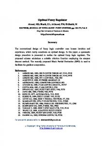
In this section, we investigate the complexity of Algorithm C in terms of the number of iterations and present a technique to improve the complexity utilizing a method called multibit shifting. The multibit shifting was first introduced in [18]. We adopt the same multibit shifting approach for Phase I of the Algorithm C while for Phase II, we propose a slightly different version that requires no precomputed values. Multibit shifting methods used for Phase I and Phase II of the Algorithm C can be applied to two phases of Algorithm B in a similar manner, and yields an overall comparable improvement, thus the details of multibit shifting for Algorithm B is deliberately omitted. A decisive figure in determining the complexity of inversion algorithm is the number of iterations of the big loop of Phase I, denoted as k. The iteration number k determines the number of operations performed such as addition, subtraction, comparison, and shifting2 . The number of iterations before termination is unpredictable, but the algorithm demonstrates a regular and familiar distribution for k. Thus, we provide the result of statistical analysis on the number of iterations for both Algorithm A and Algorithm C in Figure 1. The distribution of k in Figure 1 is obtained using 100 different 160-bit prime numbers and 100 different inversion calculations for each prime. Algorithm A and Algorithm C demonstrate almost identical statistical behavior (or more precisely an unimportant degradation in Algorithm C). The expected value of k is about 226 for both algorithm which is about 1.4 times the bit length of the prime modulus p. The latter observation is confirmed by statistical analysis for GF (p) with larger moduli. The results for these larger moduli are shown in Table 1. 2
Note that multiplication and division by 2 is just one bit shift operation to the left and right, respectively.
8
700 Algorithm A Algorithm C 600
500
400
300
200
100
0 160
180
200
220 iteraton number − k
240
260
280
Figure 1: Distribution of k in Algorithm A and C for 160-bit primes
n (bit length of p) 160 192 224 256
Algorithm A 226 271 316 360
Algorithm C 228 274 320 365
Table 1: The expected values for k with primes of different sizes. In the original Montgomery inversion algorithm (i.e. Algorithm A), the expected behavior of Phase I is that steps 4, 5, 6, and 7 are executed almost the same number of times. Consequently the k loop performs shift operations half of the time (steps 4 and 5), and addition/subtraction operations (steps 6 and 7) in the other half. For future reference, we use the term shift operations for the former and addition operations for the latter, respectively. Similarly in Algorithm C, steps 5, 6, and 11 performs shift operations while steps 7, 8, and 12 performs addition operations. In Table 1, for instance, for 160 bit prime, one can conclude that 114 iterations out of 228 in Algorithm C are spent on shift operations. For binary extension field GF (2n ) where n is chosen in the same range as in Table 1, the ratio of the expected number of iterations over n is found to be around 1.7 while the distribution function has exactly the same form and features a close resemblance to that of the so-called almost inverse algorithm in [7]. We must note that the higher expected number of iterations increases the complexity of Phase I of both algorithms. However, it decreases the number of iterations in Phase II. Therefore, a larger k does not necessarily mean a higher complexity in our setting when both phases are taken into consideration. In the next section, we show how the number of iterations is reduced using multi-bit shifting method.
5.1
Multibit Shifting for Phase I
Multibit shifting requires that the three least significant bits of u or v be inspected instead of just making an evenness check. At times it is possible to shift the integer more than one bit to the 9
right. For instance, when the least significant three bits of u are all zero (i.e. u2 u1 u0 = 000) it is possible to shift u to right by three bits. While this check increases the hardware negligibly, the net effect of this technique on the complexity is not obvious and requires statistical analysis. Our experiment with the precision range given in Table 1 (i.e. [160, 256]) shows that there is about 42%3 reduction in the number of shift operations when three-bit shifting is applied. It has also been observed that three-bit shifting provides the optimum performance improvement. The exact number of shift operations when multibit shifting is applied is tabulated at the end of this section along with the overall effect of the multibit shifting on the complexity.
5.2
Multibit Shifting for Phase II
The loop in Phase II of Algorithm C executes 2n − k times after k is determined as the output of Phase I. Each iteration involves a subtraction operation and left shift operation by one bit. As in the case of Phase I shifting, it is also possible to shift s more than one bit in an iteration depending on the most significant bits of u. For instance, it is possible to shift s to left by three bits when sn−1 sn−2 sn−3 = 000. The result may be greater than p, hence it must be brought back to the range of [1, p − 1]. The algorithm for Phase II of Algorithm C with three-bit shifting, which provides the maximum reduction in the number of iterations with an insignificant cost in hardware, is given below. Phase II with Three-bit Shifting Input: s ∈ [1, p − 1], p, and k from Phase I Output: b ∈ [1, p − 1], where b = a−1 22n (mod p) 26: i := 1 27: t := sn−1 sn−2 sn−3 28: if i < 2n − k then 29: if t = 0 then 29-a: u := 8s 29-b: v := 8s − p 29-c: i := i + 3 30: else if t = 1 then 30-a: u := 4s 30-b: v := 4s − p 30-c: i := i + 2 31: else if t = 2 OR t = 3 then 31-a: u := 2s 31-b: v := 2s − p 31-c: i := i + 1 32: else 32-a: u := 2s 32-b: v := 2(s − p) 32-c: i := i + 1 33: if (v < 0) then s := u 34: else s := v 3 The reduction in percentage is obtained by subtracting the number of shift operations after multibit shifting is applied from the number of shift operations without multibit shifting and then dividing it by the latter.
10
35: return b := s A similar algorithm can be given for Phase II of Algorithm B. The sign check on v can be done in the same manner by checking whether vn is 0 or 1 since vn = 1 implies that v is negative. Our experiments for Phase II of both algorithms with three-bit shifting is found to be the optimum choice providing about 30% reduction in the number of iterations.
5.3
Overall Effect of Multibit Shifting on Number of Iterations
We conducted some experiments in which we used 100 different prime numbers of varying precisions namely 160, 192, 224, and 256 bits. For every prime number, we computed the Montgomery inverse of 100 different integers, totalling 10000 inverse computations. The results are tabulated in Table 2. n
No. of shifts in Phase I
(bits)
Alg. A
Alg. C
160 192 224 256
113 135 158 180
66 78 91 104
Reduction in shifts 42% 42% 42% 42%
No. of iterations in Phase II Alg. A
Alg. C
92 111 128 147
67 78 91 103
Reduction in Phase II 27% 30% 29% 30%
Reduction in total number of iterations 22% 23% 23% 23%
Table 2: Reduction in number of shifts and total number of iterations. In Table 2, the total number of iterations is defined as: number of addition operations in Phase I + number of shift operations in Phase I + number of iterations in Phase II. We have mentioned previously that half of the values of Algorithm A and Algorithm C in Table 1 are addition operations and the other half shift operations. We use the addition operation values from Table 1 and shift operation and # of iterations from Table 2 while computing total number of iterations. Reduction in total number of iterations, as reported in the last column of Table 2 is percentage decrease in total number of iterations for both Algorithm A and Algorithm C.
6
Comparison with Other Inversion Algorithms
The paucity of hardware architectures implementing inversion algorithms hinders a fair comparison of different inversion algorithms from the perspective of hardware implementation. Many inversion algorithms are designed to be implemented in software on general-purpose processors. It is difficult to predict how efficiently hardware implementations of these algorithms will perform. In this section, we try to address this issue and determine the factors that are decisive in the performance of a hardware implementation. Finally, using these factors we compare Algorithm C against three other inversion algorithms. As mentioned before, many inversion algorithms are binary variants of extended Euclidean algorithm. Typically, these algorithms consist of a main loop executing a number of times. The number of iterations before termination demonstrates a familiar distribution whose statistics are shown in Figure 1. Each iteration incorporates different combinations of iterations such as addition operations, shift operations, addition operations followed by shift operations, etc. Which combination is executed in a particular iteration is determined using certain conditional check operations 11
such as parity check (e.g. Steps 4 and 5 of Algorithm A), integer or degree comparison (e.g. Step 4 of Algorithm B), etc. The expected number of these operations and/or certain combinations of these operations determines the complexity of the algorithm from the perspective of hardware implementation. In order to compare different inversion algorithms, we classified the operations as follows: (i) standalone shift operations that cannot be executed along with an addition or subtraction operation simultaneously, and (ii) addition operations that are basically addition or subtraction operations. For example, Steps 5 or 6 of Algorithm C are standalone shift operations, while (u − v)/2 in Step 7 of the same algorithm is considered as an addition operation. Although the latter has also a shift following the subtraction, it is considered as an addition operation since this shift can be incorporated into an adder while designing the hardware. Also assuming that we can employ as many adders or shifters as we need, we consider operations that can be executed simultaneously by different units working in parallel, as only one operation. In case addition and shift operations are executed in the same iteration in parallel, we count it as a single addition operation4 . For example, Step 7 of Algorithm C is counted as a single addition operation. Number of Shifts
Number of Additions
550
500
Total Number of Operations
400 Alg.C [7] [2] [11]
800 Alg.C [7] [2] [11]
Alg.C [7] [2] [11]
350
700
300
600
450
# of adds/subs
# of shifts
350
300
250
# of iterations
400
250
500
200
400
150
300
200
150
100
50 150
200 250 precision
300
100 150
200 250 precision
300
200 150
200 250 precision
300
Figure 2: Comparison of four algorithms in terms of number of operations
Under these assumptions, we compared four algorithms, Algorithm A in [6], Algorithm C pro4 Note that we assume that adders and shifters are inexpensive and that including up to four adders or shifters bring about no significant overhead in design area. In our scalable design, these units are inexpensive comparing to memory and control logic. With other design approaches such as ones requiring very long full-precision adders, this assumption does not hold.
12
posed in this paper, the inversion algorithms proposed by Brown et. al. in [14] and by Lorenz in [16]. Algorithm A and Algorithm C are proposed for Montgomery arithmetic, and Algorithm C is basically a variant of Algorithm A optimized for hardware implementation. On the other hand, algorithms in [14, 16] do not use Montgomery arithmetic. Excluding the conditional checks such as parity check or integer comparison, we counted the number of standalone shift operations and additions by running these four algorithms 10000 times (with 100 different integers whose inverses to be calculated for 100 different primes). In Figure 2, the statistics obtained from this experiment are displayed. As can be observed in Figure 2, the number of shift operations in Algorithm C is much fewer than those in the other three algorithms owing to multibit shifting technique. Lorenz’s algorithm in [16] has the fewest number of addition operations. In terms of total number of operations, Algorithm C compares favorably with others. As shown in the next section where the details of our hardware architecture are discussed, shift and addition operations are of equal cost in terms of number of clock cycles because of the scalable nature of the architecture. Therefore, Algorithm C that has the fewest expected number of operations in total is the best choice for our design. For other architectures taking different approaches the best choice may be different. For example, Lorenz’s algorithm in [16] may perform better where the shift operations are much less expensive than additions.
7
Hardware Architecture
Algorithms B and C presented in Section 3 and 4 respectively are suitable for scalable and unified design. Before discussing the details of the design issues involved we will give definitions of scalable and unified architectures for arithmetic operations. Scalability : An arithmetic unit is called scalable if it can be reused or replicated in order to generate long-precision results independent of the data path precision for which the unit was originally designed. Scalability of the arithmetic modules is important in cryptographic context since it allows an increase in the key length when the need for more security arises without having to modify or re-design the cryptographic unit. The scalability of the inverter unit can easily be achieved by using shifter and adder units, which handle only certain numbers of bits at a time. One addition (or shift) operation, therefore, in the corresponding field takes more than one clock cycle since the operands can be represented in multiprecision format. The number of bits that the unit operates on is referred as word and the length of the word is yet to be determined. The word length cannot be too small since this increases the clock cycle count leading to a slow execution of the whole operation. On the other hand, using long word units leads to other complications such as longer latency and higher gate count during hardware realization. 16, 32, and 64-bit block adders and shifters provide reasonable latency and gate counts. The length of a word can be determined or adjusted with respect to given area, speed or latency requirements. Unified Architecture: Even though prime and binary extension fields, GF (p) and GF (2n ) respectively, have dissimilar properties, the elements of both fields are represented using almost the same data structures in digital systems. In addition, the algorithms for basic arithmetic operations in both fields have structural similarities allowing a unified module design methodology. Therefore, a scalable arithmetic module which is versatile in the sense that it can be adjusted to operate in both fields is feasible, provided this extra functionality does not lead to an excessive increase in area and dramatic decrease in speed. In addition, designing such a module must require only a small amount of extra effort and no major modification in control logic of the circuit. 13
The algorithms B and C can be implemented in a unified hardware architecture provided a dual-field adder/subtracter (DFA/S) that operates in both fields is available. In order for the inverter unit to be scalable, the DFA/S is designed to operate on words at a clock cycle rather than the whole operand. Hence, it is referred as word-DFA/S(or WDFA/S). In addition to WDFA/S, a bidirectional shifter, which is able to shift one word to left or right at a clock cycle is needed to perform the shift operations. Except the check in step 15 of Algorithm C, the main loops of the Algorithm B and Algorithm C are almost identical and using the same local control circuitry these loops can be implemented in the same data path. The only difference in the main loops of the two algorithms is that the Algorithm C has an additional step for checking the sign of u. However, this extra step neither necessitates a major change in the circuitry nor introduces any extra clock cycle in the computation since this part of the logic can simply be disabled when operating in GF (2n )-mode because there are no negative numbers in GF (2n ). Algorithm C which is executed in GF (p)-mode, replaces the integer comparison operation of the original algorithm with just one bitsize comparison. In exchange for that, u takes negative integer values because of this imperfect comparison. Therefore, the variables u and r may have to change sign if the subtraction operation in Step 7 produces a negative result. Performing these two negation operations immediately after Step 7 would necessitate extra clock cycles which may be more expensive than the integer comparison operation. Therefore, these two negation operations (i.e. taking two’s complements of u and r) are performed in the next iteration of Algorithm C (Step 11 or 12). To perform the negation operations concurrently with two addition/subtraction operations in the next iteration, besides two WDFA/Ss we need two negators, which can be implemented as a relatively less complicated word adder. By having two extra negators, which may have a limited impact on the area as demonstrated by our implementation results, no extra clock cycles are spent on comparison operations. In a similar implementation presented in [18], the comparison is done utilizing a full subtraction. In [18], in order to avoid extra clock cycles due to this subtraction operation three extra full-length registers are employed leading to a substantial increase in chip area. In the implementation in [18], both (u − v)/2 and (v − u)/2 are computed and the negative of the results are discarded. For example, if (u − v)/2 is negative then u < v, hence the operation that must be performed is actually (v − u)/2. However, some extra clock cycles are still needed to perform two subsequent shift operations. On the other hand, our proposed algorithm eliminates the need for these extra clock cycles as well as three extra registers of full precision. The only extra cost for the comparison is two negators. Therefore, our implementation calculates inversion faster and requires less chip space than the one in [18]. The sign of the integer u is set to positive initially. The operation u = (u − v)/2 is completed at most in e = �n/w� clock cycles. In the (e + 1)-st cycle, all control information, the sign of u, bitsize of u and v become available, hence next iteration can start in the (e + 2)-nd clock cycle. This basically means that one iteration takes (e + 1) clock cycles to finish. Note that the operation r + s may need (e + 1)-st clock cycle to complete since s may get two bits longer than the modulus. The WDFA/S, performing (u − v)/2 (or (v − u)/2) operation on word-by-word basis, also calculates the bitsize of the result in the same manner. When (u − v)/2 operation starts, the bitsize of the result is initially set to zero. When the first word of the result is generated its bitsize is stored in a temporary register without disturbing the bitsize of the result on which subsequent word computations depend. After e clock cycles the bitsize of the result is fully calculated and hence, it is updated from the temporary register. In the (e + 1)-st cycle after (u − v)/2 operation started, this information is used to determine how to proceed with the calculations. In the same clock
14
cycle, the bitsize of the result is also checked to determine whether it is zero. A result with zero bitsize indicates the termination of the computations (step 4 of Algorithm C). Note that bitsize of a negative u is meaningless and the algorithm terminates after u becomes 1. Therefore, a negative result only indicates that the computations must carry on. In Table 3 below, an example for the calculation of u := (u − v)/2 is given for 160-bit operands. The operands u and v can be expressed as five-word multiprecision numbers where each word is 32-bit( e.g. u = (u(4) u(3) u(2) u(1) u(0) ). As can be observed in steps 5, 6, 7, 8, 11, 12 of Algorithm C, one of the six different operations may update the values of u, v, r, and s in each clock cycle. These operations are distinguished by an operation code (opcode for short) and the opcode must be determined in the preceding clock cycle before an operation starts. In clock cycle 1, the operation (u(0) − v (0) )/2 is performed assuming that the opcode is known. The result of this operation is the least significant 31 bits of (u(0) − v (0) )/2 and the most significant bit is yet to be computed in the next clock cycle. Thus, the result is not considered to be ready and in the next cycle the result is written to the register. In other words, the result of (u(0) − v (0) )/2 is available in register file in clock cycle 2. This calculation continues until all the words of u and v are exhausted in clock cycle 5. In the following cycle(i.e. clock cycle 6), the complete result of (u − v)/2 operations becomes available in the register and the opcode is calculated for the next iteration. Clock Cycle 1 2 3 4 5 6
Operation
Output of adder
(u(0) − v (0) )/2 (u(1) − v (1) )/2 (u(2) − v (2) )/2 (u(3) − v (3) )/2 (u(4) − v (4) )/2 opcode for the next iteration is calculated
(u(0) − v (0) )/2[30 : 0] (u(1) − v (1) )/2[30 : 0] | (u(0) − v (0) )/2[31] (u(2) − v (2) )/2[30 : 0] | (u(1) − v (1) )/2[31] (u(3) − v (3) )/2[30 : 0] | (u(2) − v (2) )/2[31] (u(4) − v (4) )/2[30 : 0] | (u(3) − v (3) )/2[31]
Result available in register file (0) (0) (u − v )/2[31 : 0] (u(1) − v (1) )/2[31 : 0] (u(2) − v (2) )/2[31 : 0] (u(3) − v (3) )/2[31 : 0]
-
(u(4) − v (4) )/2[31 : 0]
Table 3: Execution steps of (u − v)/2 with operands of five words where word length is 32. In Figure 3, the block diagram for Phase I of the inversion module is illustrated. Adder Building Block contains two WDFA/Ss and two negators while Register Block contains registers for four intermediate variables, u, v, r, and s. Main Control Block is responsible for generating the opcode and selecting which part of the register block is used and updated in each clock cycle. The information the control block uses to determine the opcode, such as the bitsize, the parity of u and v, and the sign of u is kept in the block named Registers/Flags. Before an iteration starts, the control block updates some of these values and subsequently uses them for generating the opcode for the next iteration. Note that the opcode remains unchanged for e clock cycles after it is set where e is the number of words in the operands. To keep track of this, a counter is introduced in the design (counter(m)). When u becomes 0, the control block activates the done signal indicating that the computation is terminated and the results are available in register s and at the output kout of the control block. tmp reg is used to store words of operands during shift operations while the carry register holds the carry as a result of addition or subtraction of two words. bitsize tmp register keeps the intermediate values of bitsize of u and v, while the current value is kept in Registers/Flags. These 15
load_u
carry reg.
load_v Adder Building Block
load_r tmp_reg (w-bit)
Register Block for u, v, r, s
load_s
u
FSEL
CE
v r s
Add /Sub
zu zv zr zs tmp_ reg_ out
tmp_ reg_ in
u v r s
Main Control Block k_out done
v_bitsize u_bitsize v_even Registers/Flags k
bitsize_tmp
counter(k)
m
u_even u_pos
counter(m)
reset CLK
Figure 3: Block diagram of module implementing Phase I
new values are used to update Registers/Flags in the last clock cycle of the current iteration. The main control block takes a word of u, v, r, and s from the register block each clock cycle and supply them to the adder block. Each of the four adders produce the results in outputs zu , zv , zr , and zs . The control block decides how to update the register block with these values. Note that the module in Figure 3 implements the Step 1 through Step 14 of the Algorithm C (Step 1 through Step 8 of Algorithm B) and the rest of the Phase I is implemented along with Phase II using a different control logic which is not shown here and referred from now on as Phase II control logic. Phase II control logic is less complicated than the main control block shown in Figure 3 and uses the same register and adder blocks. We only report the area requirements of the Phase II control logic in the next section since its critical path delay do not increase the overall critical path.
16
8
Implementation Results
In this section, we present some implementation results of the inversion unit capable of operating in both GF (p) and GF (2n ). We synthesized the unit using Synopsys tools with 0.18µm CMOS technology [19]. During the synthesis, no optimization method is applied; hence the figures presented here can be further optimized using standard optimization options of Synopsys tools. Implementation results consists of three categories: (i) area requirements (ii) maximum applicable clock frequency (critical path delay) (iii) number of clock cycles to compute an inversion operation. Time and area requirements of main blocks in our design are reported separately. This facilitates accurate estimation of these requirements for inverters with different precisions and word lengths etc. For instance, doubling the word length immediately results in almost two-fold increase in area of adder and control blocks, while causing a relatively small increase in critical path delay of these blocks. Similarly, there is a linear relation between the register block size and the precision of the operands. As noted before, the adder block should normally contain two adders and two negators operating on the words of the operands. In our implementation, however, we use four WDFA/Ss in the adder block in order to make the design more regular. Table 4 shows time and area costs of a single WDFA/S and total cost of adder block for different precisions that can be used for cryptographic applications. word length (w) 16 32 64
Propagation Time (ns) 1.65 1.93 2.31
Area (in NAND gates) 198 451 989
Total Area (in NAND gates) 792 1804 3956
Table 4: The time and area costs of block adder with w = 16, w = 32, and w = 64. Similarly, we give the area cost of the register block for various operand precisions as in Table 5. bitsize 1 160 192 224 256
Area (in NAND gates) 30 4800 5760 6720 7680
Table 5: The area cost of register block with various precisions. We also implemented the control blocks for two word lengths, w = 16 and w = 32 and give the results in Table 6. We did not implement the control blocks for w = 64; however we estimate a two-fold increase in the area and less than 10% increase in the critical path delay. word length (w) 16 32
Main Control Time Area Delay (ns) (NAND gates) 4.00 3474 4.40 6369 17
Phase II Control Time Area Delay (ns) (NAND gates) 1.87 779 2.01 1970
Table 6: The time and area costs of control blocks Based on the figures in Tables 4, 5, and 6, area and time requirements for a 160-bit inverter with w = 32 are reported in Table 7. Note that these figures are comparable to those in [18]. We avoid a direct comparison because of the different technologies used. Also such comparison may be misleading since the main focus of the work in [18] is to compare the scalable implementation against fixed-precision implementation.
Area (in NAND gates) Time Delay (in ns)
Adder (32-bit) 1804 1.93
Register 4800 Negligible
Main Control 5867 4.34
Phase II Control 1970 2.01
Overall 14441 4.34
Table 7: The area and time requirements for a 160-bit inverter with w = 32 Besides time and area, the number of clock cycles to complete an inversion operation is also important in assessing the efficiency of an inversion module. We provide expected values for the number of clock for certain precisions based on the figures in Tables 1 and 2. As pointed out earlier, an iteration of the loops in Phase I and Phase II takes exactly e + 1 clock cycles to finish where e = �n/w�. In addition to these steps, some intermediary steps are necessary to bring s in the correct range (i.e. steps 9 to 14 of Algorithm B and steps 15 to 25 of Algorithm C). These steps take an additional 2(e + 1) clock cycles. Taking into account the initialization steps, which take e + 1 clock cycles, we need to add 3(e + 1) extra clock cycles to clock cycles spent on the main loops of Phase I and II. As an example, based on the figures in Table 1 and 2 and considering additional clock cycles mentioned above, we calculated expected execution time in terms of number of clock cycles for an inversion operation using word length 32. The results are summarized in Table 8. Table 8 also includes the clock cycle count estimates for the modular multiplication operation for the same precisions, which is assumed to be performed using unified and scalar Montgomery modular multiplication unit proposed in [12] with 7 pipeline stages and 32-bit word size. The ratio of inversion time to multiplication time, which is important in the decision whether affine or projective coordinates are to be employed in elliptic curve cryptography, is also included in the table. It is argued in [17] that for binary extension fields GF (2n ) projective coordinates, which does not entail fast execution of inversion operation, perform better than the affine coordinates when the inversion operation is more than 7 times slower than the multiplication operation. Similarly, our calculations show that this ratio is about 9 for prime field GF (p). As can be observed in Table 8 the ratio stays lower than 7 for the precision of interest to the elliptic curve cryptography. The ratios achieved here are better than the previous work of [11] that employs similar inversion algorithms. Note that, unlike the current work, [11] does not report on the time complexity of Phase II of the algorithm. The improvement is largely due to the multibit shifting techniques used in the two Phases of the algorithm.
18
Inversion n (bits) 160 192 224 256
Phase I + Phase II 1920 2695 3584 4608
After Multibit shifting 1498 2075 2760 3548
Extra Clock Cycles 18 21 24 27
Total Number of Clocks 1516 2096 2784 3575
Multiplication
Ratio
327 398 469 526
4.6 5.27 5.94 6.80
Table 8: Estimated clock cycle counts for inversion and the ratio to the multiplication operation. However, one must also consider that the maximum critical path delay of the inverter can be greater than that of a multiplier because of the more complicated control logic of the inverter. Therefore, in case a multiplier that utilizes a faster clock is employed, the ratios in Table 7 are subject to changes depending on the difference in the clock rates.
9
Conclusion
We presented two multiplicative inversion algorithms for GF (p) and GF (2n ) which are suitable for scalable and unified hardware implementations. The hardware implementation of these algorithms is easy, fast and area efficient. We presented experimental results and estimated values to show the practicality of the new algorithms. We also reported on the time and area complexity of the inversion unit using our implementation results. It turns out that the two new algorithms presented in this paper can enable hardware implementations that calculate inversions at such a speed that the usage of projective coordinates in elliptic curve cryptography no longer offers a significant advantage over affine coordinates. While projective coordinates [20] does not necessitate an inversion unit, they require considerably more temporary storage space than affine coordinates. Therefore, the extra design space used to implement an inversion unit may not be significant.
References [1] D. E. Knuth. The Art of Computer Programming. vol. 2, Reading, Mass, Addison-Wesley, 2nd edition 1981. [2] W. Diffie and M. E. Hellman. New directions in cryptography. IEEE Transactions on Information Theory, 22:644–654, November 1976. [3] National Institute for Standards and Technology, “Digital Signature Standard (DSS)”, Federal Register , 56:169, Aug 1991. [4] N. Koblitz, “Elliptic curve cryptosystems”, Mathematics of Computation, 48(177):203–209, Jan 1987. [5] A. J. Menezes. Elliptic Curve Public Key Cryptosystems. Kluwer Academic Publishers, Boston, MA, 1993.
19
[6] B. S. Kaliski Jr., “The Montgomery inverse and its applications”, IEEE Transactions on Computers, 44(8):1064–1065, Aug 1995. [7] R. Schroeppel, H. Orman, S. O’Malley, and O. Spatscheck, “Fast key exchange with elliptic curve systems”. In D. Coppersmith, editor, Advances in Cryptology — CRYPTO 95, Lecture Notes in Computer Science, No. 973, pg 43-56, 1995. [8] T. Kobayashi and H. Morita, “Fast modular inversion algorithm to match any operand unit”, IEICE Trans. Fundamentals, E82-A(5):733-740, May 1999. [9] E. Sava¸s and C ¸ . K. Ko¸c, “The Montgomery modular inverse - revisited”, IEEE Transactions on Computers, 49(7):763–766, Jul. 2000. [10] M. A. Hasan, “Efficient computation of multiplicative inverses for cryptographic applications”, Technical Report CORR 2001–03, Centre for Applied Cryptographic Research, 2001. [11] E. Sava¸s and C ¸ . K. Ko¸c, “Architecture for unified field inversion with applications in elliptic curve cryptography”. In Proc. vol. 3, The 9th IEEE International Conference on Eelctronics, Circuits and Systems - ICECS 2002, pg. 1155-1158, Dubrovnik, Croatia, Sept 2002. [12] E. Sava¸s, A. F. Tenca, and C ¸ . K. Ko¸c, “A scalable and unified multiplier architecture for finite m fields GF (p) and GF (2 )”. In Cryptographic Hardware and Embedded Systems, Workshop on Cryptographic Hardware and Embedded Systems, pg. 277-292. Springer-Verlag, Berlin, 2000. [13] S. C. Shantz, “From Euclid’s GCD to Montgomery multiplication to the great divide”. Technical Report SMLI TR–2001–95, Sun Microsystems Laboratory Technical Report, Jun. 2001. [14] M. Brown, D. Hankerson, J. Lopez and A. Menezes, “Software implementation of the NIST curves over prime fields”, Technical Report CORR 2000–56, Centre for Applied Cryptographic Research, 2000. [15] D. Hankerson, J. Lopez, and A. Menezes, “Software implementation of elliptic curve cryptography over binary fields”, Technical Report CORR 2000–42, Centre for Applied Cryptographic Research, 2000. [16] R. L´orenz, “New algorithm for classical modular inverse”. In B. S. Kaliski Jr., C. K. Koc, and C. Paar, editors, Cryptographic Hardware and Embedded Systems, LNCS, pg. 57-70, Springer-Verlag, Berlin, 2002. [17] J. Lopez and R. Dahab, “Fast multiplication on elliptic curves over GF(2m ) without precomputation”. In Cryptographic Hardware and Embedded Systems, Workshop on Cryptographic Hardware and Embedded Systems, pg 316–325, Springer-Verlag, Berlin, 1999. [18] A. A.-A. Gutub, A. F. Tenca, E. Sava¸s, and C ¸ . K.Ko¸c, “Scalable and unified hardware to ¸ . K.Ko¸c and C. compute montgomery inverse in GF (p) and GF (2n )”. In B.S. Kaliski Jr., C Paar, editors, Cryptographic Hardware and Embedded Systems, LNCS, pg. 485-500, SpringerVerlag Berlin, 2002. [19] UMC 0.18µm CMOS processf amily. http://www.umc.com/english/process/d.asp. [20] IEEE. P1363: Standard specifications for public-key cryptography. 2000.
20