EFFICIENT VIDEO DISSEMINATION IN STRUCTURED HYBRID P2P NETWORKS Thinh Nguyen Krishnan Kolazhi Rohit Kamath {thinhq, krishnan, kamathr}@eecs.orst.edu School of EECS Oregon State University Corvallis, OR 97330
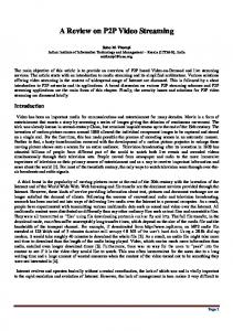
1. ABSTRACT In this paper, we propose a structured hybrid P2P Mesh for optimal video dissemination from a single source node to multiple receivers in a bandwidth-asymmetric network such as Digital Subscriber Line (DSL) access network. Our hybrid P2P structured mesh consists of one or more Supernodes responsible for node and mesh management and a large number of streaming nodes, Peers. The peers are interconnected in a special manner designed for streaming and realtime video dissemination and are responsible for the actual data delivery. Our proposed hybrid P2P structured mesh is designed to achieve scalability, low delay and high throughput. Our experimental Internet-wide system consisting of PlanetLab nodes demonstrates the aforementioned qualities. 2. INTRODUCTION Many video multicast applications rely on the network topology and protocols for efficient data dissemination from a single source node to a large number of destination nodes. IP Multicast is a well known example of data dissemination over the Internet. IP Multicast is implemented at the network layer to prevent packet duplication on the physical link. However, IP Multicast is not widely deployed due to compatibility issues across Autonomous Systems(AS). Hence overlay multicast systems are preferred. In an overlay multicast system, the application layer performs the sophisticated functions, leaving the underlying routers unchanged. However, traditional overlay multicast is not optimal in terms of throughput since the leaf nodes do not contribute their bandwidth to the system. Recent works [1][2][3] employ P2P model to increase the resilience and throughput of the system. In this paper, we design a hybrid peer-to-peer (P2P) system that achieves scalability, low delay and high throughput. Assumptions : 1. The download bandwidth of a node is larger than its upload bandwidth. Hence, the bandwidth bottleneck is due to the upload capacity of a node. This assumption holds true for the networks consisting of DSL subscribers or wireless networks, and 2. Due to the limited scope of this paper, we assume that the upload capacities of all nodes are approximately the same in order to simplify our discussion. 3. TOPOLOGY 3.1. Balanced Mesh In [4], we show that a b-balanced mesh topology as in Figure 1 results in maximum dissemination throughput and at the same time, achieves a trade-off in delay and out-degree. b is the outdegree of a node. The key observation is that in order to achieve maximum throughput, every node must send useful data. Thus, unlike the traditional multicast, the topology in Figure 1 enables the leaf nodes to send data. To prevent data duplication at the receivers, the source node partitions the data into distinct segments and sends these distinct segments onto different downstream links. Each internal node
1424403677/06/$20.00 ©2006 IEEE
Sen-ching S. Cheung
[email protected] ECE Department University of Kentucky Lexington, KY 40506
Source A
B 0
1
2
A
A
3
4
A B A
7
8
B
5
A
B
B
9
A
10
B
6 B
A
11
B
A
12
B
A
B
13
14
Fig. 1. Balanced mesh. then forwards the same data segment on its downstream links. The leaf nodes then exchange data segments with other leaf nodes. The data segments are then forwarded to the ancestor nodes in such a way that all the nodes receive the complete data segments. Figure 1 shows a 2-balanced mesh. The source partitions the data into two segments A and B and sends them down onto different links. In [4], we present an algorithm for building this type of balanced mesh for different outdegree b. A larger outdegree b results in a shorter delay. However, this may lead to higher cost of link management and resources. At the limit, if every node connects to all other nodes, then the delay is short. However, in such a case when one node leaves the network, all other nodes are affected. 3.2. b-Unbalanced Mesh One significant drawback with the b-balanced mesh is that the numn ber of nodes must be of the form 1−b where n is the level num1−b ber in the mesh. In this paper, we present a b-unbalanced mesh that does not suffer this drawback. The key idea is to cascade multiple bbalanced meshes. For convenience, we denote the mesh containing the source node as the primary mesh and other meshes connected to the primary mesh as secondary meshes. In order to achieve low delay, the number of nodes in the secondary meshes is limited to b2 − 1. Once the number of nodes reaches b2 , we destroy the secondary mesh(es) and attach the secondary mesh nodes at appropriate places in the primary mesh. 3.2.1. Constructing and maintaining the b-unbalanced mesh Assume that we already have in place a balanced primary mesh. When a new node joins the network, it acts as the root node of the secondary mesh. Now, when another node joins the network, it is added to the secondary mesh using the algorithm for constructing the b-balanced mesh as described in [4]. This process repeats as long as the number of nodes in the secondary mesh(es) is fewer than b2 . Once the node count reaches b2 , we destroy the secondary mesh and join the nodes to the primary mesh as described below. Since there are b2 new nodes, they can be attached to b nodes in the primary mesh. In particular, the first b new nodes will be attached to the first node from left to right within the first group. The second b new nodes will be attached to the first node from left to right within the second group. The process continues until
1673
ICME 2006
Source host 0
1 3
7
8
4
9
5
6
12
11
10
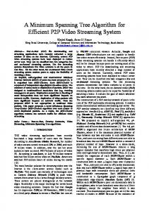
a secondary mesh consisting of b2 − 1 nodes associated with the departing node is constructed. If the departing node belongs to a secondary mesh, rebuild the secondary mesh. It can be proved that in the P2P mesh, the number of nodes affected by a node removal or insertion is at most O(b2 ), the delay is of O(logb) and the throughput is maximum. Thus, this topology is efficient and scalable as the node management and mesh maintenance overhead does not depend on the number of nodes.
2
13
15
16
14
17
(a) 0
1 3
7
15
4
8
9
16
2
5
10
17
6
11
12
13
14
18
(b) Fig. 2. (a) The mesh immediately before the destruction of the secondary mesh; (b) immediately after the destruction of the secondary mesh. the last b new nodes are attached to the first node in the rightmost group. When b new nodes attach to a node P in the primary mesh, node P disconnects b − 1 connections to other nodes in other b − 1 groups and one connection that is used to forward data from one other group to its ancestor. With the availability of b connections, node P can forward data from its parents to b new nodes. The b new nodes are then connected to other nodes in other groups in a similar manner as described in the balanced mesh. Since the ancestor of node P no longer receives the data from the other branch, the rightmost node of the new b children of P will forward the data to P ’s ancestor. Now if more nodes join, another secondary mesh is constructed. After bj−1 new nodes join, where j is the depth in the primary mesh, the primary mesh is balanced and its depth increases by 1. Figure 2 illustrates the incremental construction of a 2-unbalanced mesh. Initially, the primary mesh consists of 15 nodes. Figure 2(a)shows the resultant topology after 3 new nodes join. When the fourth node joins, the secondary mesh is destroyed and its nodes are attached to the nodes in the primary mesh. Nodes 15 and 17 are attached to node 7, nodes 17 and 18 to node 11. Node 7 and 11 are disconnected from each other. They also no longer forward data to their ancestors. Instead, they use these two extra connections to forward data to the new nodes. Node 15 and 16 then exchange the data with nodes 17 and 18 as before. Node 15 also forwards data from other group to its parent (node 7) and node 16 forwards data from other branch to its grandparent (node 3). Thus, all nodes receive complete data. 3.2.2. Node Deletion If the departing node belongs to the primary mesh, perform one of following steps: 1. If there exists a secondary mesh, pick a node that belongs to the secondary mesh to replace the departing node. This step maintains the same structure for the primary mesh. Next, rebuild the secondary mesh. 2. If there is no secondary mesh and the departing node is not of the largest depth, pick a leaf node in the primary mesh with the largest depth to replace the departing node. Next, construct a secondary mesh consisting of the b2 − 1 nodes. These b2 − 1 nodes are the siblings of the chosen node, i.e. the nodes in other groups that connect directly to the departing node and their siblings. If the departing node is of the largest depth, node replacement is not necessary and
4. SYSTEM ARCHITECTURE Although the proposed b-unbalanced mesh can be built in a completely distributed way, we believe a hybrid P2P architecture offers many more benefits. A hybrid P2P architecture enables scalable data dissemination among the nodes and at the same time, provides other benefits such as security and flexibility due to the centralized management. We now briefly discuss our hybrid architecture. In our proposed hybrid P2P network, a node is classified as either a Supernode or a Peer. 1. Supernode: A Supernode is the controller of the system as it performs all necessary mesh management functions. It is a special node which handles requests from other nodes for joining or leaving a session. Its task is to maintain an accurate global view of the topology of a session. A supernode can handle multiple sessions, i.e. multiple topologies. An Algorithm Component (AC) running on the supernode is responsible for producing a list of affected nodes and the corresponding actions when a new node joins or leaves the network. The supernode then uses the outputs from the AC to send out appropriate messages to other nodes to instruct them with appropriate actions. 2. Peer: A peer is a node that is part of some session which is managed by a supernode. A peer is connected to other peers to form the topology. The peer gets information about its neighbors from the supernode when it joins. When a new node is added to the network, the peer’s neighbors get updated to maintain the optimal topology. In this case the peer is informed about the new neighbors by the supernode through standard messages. In addition to these main roles, a node may also be an entity only interested in obtaining information from a supernode about all the ongoing sessions. It is not part of any session and hence, not part of the whole P2P network. Once it gets a list of sessions from a supernode, it can decide whether it wants to join a session, host a session or do nothing. Once it joins a session, it becomes a peer. This node can refer to a published list of supernodes to get access to a particular supernode. 4.1. Hosting and Joining Sessions The node that desires to host a session contacts a supernode and makes a request for the same by providing information such as the streaming file name and the preferred transport protocol. Assuming that the supernode has the resources to manage the session, it creates a new Session object. Creating a session object mainly involves creating a new AC, which maintains the mesh topology for the new session. Next, the supernode sends the host a generated Session ID for the new session. Now the session is listed on the supernode and any node wanting to join this session will contact it. Figure 3 shows the interaction between a peer and a supernode when the peer wants to join a session. Whenever a node wants to join an existing session, it contacts a supernode and gets the list of sessions managed by that supernode. It then picks a session it wishes to be a part of and sends a Join request along with the Session ID to the supernode. When the supernode receives a join message from a peer, depending on the session ID, the corresponding AC for that session updates the topology to accommodate the new node. Updating the topology has two aspects. First, existing nodes have to be updated so that they can find their new neighbors. Second, the new node needs to know the nodes it is required to connect to. The AC does the work of identifying the nodes that need updating and passes on the information to the supernode. The supernode
1674
control rests with the supernode. Thus, the whole system is easy to manage and upgrade. As a drawback, the supernode may seem to be a centralized point of failure for the system. However, by ensuring that we have multiple supernodes and the session information is smartly replicated, this bottleneck can be alleviated. 5. PERFORMANCE EVALUATION
Fig. 3. Interaction between peer and supernode for join request then sends Update messages to these nodes instructing them about the change. When the change completes, the peers send back messages confirming the successful connections to the new neighbors and then, AC updates the new topology. We note that when a node joins the network, only a small number of nodes are affected and therefore, the hybrid architecture is highly scalable. 4.2. Leaving a Session When a peer wants to leave a session, it will contact the supernode. The supernode invokes the corresponding AC which then deletes the node and provides the supernode with a list of affected nodes. Next, the supernode sends out messages to these nodes informing them of the changes. Once the affected nodes make their new connections, they inform the supernode and the supernode accepts the leave request from the departing node. This process ensures that the departing node does not cause disruption to the streaming session by creating temporary disconnections. Because a node may leave the network without informing the supernode, all the neighbors also periodically send out heartbeats to each other. If a node does not receive a heartbeat from its neighbor for a predetermined period of time, it informs the supernode so as to enable it to perform the required tasks to maintain the mesh. 4.3. Advantages of the System There are a number of advantages of having a hybrid P2P system design as mentioned below : 1. Load Distribution: Since the design separates topology management and data dissemination, the peer only performs the simple task of forwarding data packets as instructed by the supernode. The complexity of running the algorithm and any issues related to optimizing the streaming performance of a session are handled by the supernode. 2. Security: Having centralized control over who joins and leaves the system prevents the malicious users from entering the network via authentication by the supernode. As an example, consider a confidential live meeting being streamed over a corporate network in which only the certain users need to participate. In this case, the supernode handling this session can authenticate incoming requests from nodes and accept or deny access accordingly. 3. Flexibility: Hybrid architecture offers high flexibility in terms of management and upgradability. Suppose, we wish to upgrade the algorithms, change the network topology or add more security/controlling features, we just need to make modifications to the supernode. The rest of the system can remain almost the same. This is because (a) the supernode sends standard messages to the peers and, (b) the peers simply follow the instructions contained in the standard messages. In addition, the system has the advantage that any changes need not be known to the peers because all the
5.1. Small Scale Deployment over PlanetLab We have built our hybrid P2P system consisting of nodes running on PlanetLab [5]. In the first set of experiments, we compare the performance of Vanilla Multicast and our hybrid P2P mesh. To be fair, we use the same set of machines with the nodes occupying the same logical position in our mesh as well as in the multicast tree. To simulate the DSL upload bandwidth bottleneck, the upload rate of a node is limited to 44KBps. Table 1 shows the upload and download speeds of individual nodes in the vanilla multicast and our proposed mesh. Both topologies consist of 15 nodes and have outdegree b = 2. As seen, the upload speeds of the non-leaf nodes in vanilla multicast are almost the same as those of the nodes in our proposed mesh. However, the download speeds of nodes in the vanilla multicast are half the speeds of the nodes in our proposed mesh. This is because the nodes in our mesh receive data from both neighbors. The bandwidth contribution of the leaf nodes is the key factor behind the efficiency of the proposed P2P mesh.
Node 0 Node 1 Node 2 Node 3 Node 4 Node 5 Node 6 Node 7 Node 8 Node 9 Node 10 Node 11 Node 12 Node 13 Node 14
Upload (KBps) Mcast 46.84 44.10 43.60 44 44 43.6 43.6 -
Speed Mesh 43 43.08 42.58 42.87 42.88 42.19 45.30 37.17 39.39 40.74 42.20 42.42 20.67 40.80 20.36
Download Speed (KBps) MCast Mesh 22.0 40.29 21.7 40.59 21.29 35.15 22 39.89 21.9 36.44 21.6 41.77 20.75 37.17 20.93 39.39 22.04 40.74 21.81 42.20 21.32 42.36 21.53 42.42 21.8 40.72 21.6 40.61
Table 1. Performance of Vanilla Multicast and our proposed structured mesh. We also compare the join times for our proposed topology with different outdegree b. In this experiment, we use two 13 node topologies, each topology has b = 2 and b = 3, respectively. As seen from Table 2, on an average, the join time is more in case of b = 3 than b = 2. The entries of interest are those for node 6 and node 10. In both the cases, the join times are significantly greater than that for b = 3. This is because when node 6 or 10 joins, for b = 2, the secondary mesh breaks and all the secondary nodes become a part of the primary mesh. As a result, the number of nodes affected is more. On the other hand, with the topology where b = 3, when node 6 or 10 joins, they do not destroy the entire secondary mesh. Similarly, in case of node 2 and node 5, the number of nodes affected for b = 2 is greater than b = 3 and hence the join time is greater. Again, when node 12 joins in for a b=3 topology, the secondary mesh breaks and larger number of nodes are affected and hence, the delay is the largest. In general, the delay is proportional
1675
b=3 Join Time(in sec) .192 .557 1.901 2.132 .352 .611 2.302 2.322 1.024 .878 2.291 5.75
Failure model for different values of b
60
b=2 b=3 b=4
55
% of nodes affected
50 45 40 35 30 25 20 15 10 1
1.5
2
2.5
3
3.5
4
% of nodes failed
(a) Failure model for different allowable failures 60
50
% of nodes affected
Node 0 Node 1 Node 2 Node 3 Node 4 Node 5 Node 6 Node 7 Node 8 Node 9 Node 10 Node 11 Node 12
b=2 Join Time(in sec) .074 .805 1.37 .866 1.202 2.534 1.374 .884 1.469 3.3837 1.232 .451
Table 2. Node Join times for b = 3 and b = 2. to the number of nodes that a join affects, which in turn increases with b. We note that the trend for leave times is also similar to that of join times.
40
30
20
10
0 1
5.2. Large Scale Deployment We now present the simulation results for our proposed structured mesh depicting the robustness of the system. The following simulations aim to quantify the effect of node failure on the proposed topology. All simulations were done using NS [6]. In these simulations, we used BRITE [7] to generate an Albert-Barabasi topology consisting of 1500 routers. Next, we randomly generate an additional 1000 overlay nodes and connect them to the existing 1500 routers. There are 2 important factors that determine how failure of a node affects others in the topology. The first one is whether the node in contention is a leaf node or an internal node and the second one is the outdegree b. If the node is an internal node, then when it fails, the number of affected nodes is more than that for a leaf node. This is because all the nodes below that internal node and the nodes in the other groups that receive data due to cross links also fail. The outdegree determines how many nodes a particular node is connected and hence provides data to. Hence, the larger the outdegree, more nodes are affected for a given failed node. Note that, in the case of vanilla multicast, if a node fails then all the nodes in its subtree are affected. Figure 4(a) shows the percentage of affected nodes as a function of failed nodes for different outdegrees. It is important to emphasize that these failures are only temporary as the network can reconstruct itself. As expected, the percentage of affected nodes increases with the percentage of failed nodes. For b = 2, the number of internal nodes is large (500 nodes) and hence the number of affected nodes is larger. It is interesting to note that for b = 3 the number of non leaf nodes is 336 and for b = 4, it is only 254. Between b = 3 and b = 4 the difference in the number of internal nodes is not large, but because of the branching factor, the affected nodes for b = 4 is higher than b = 3. If FEC or multiple description coding technique is used to disseminate the data [2][8], then a node need not receive the complete data. Thus, a node is considered a failed node if it fails to receive more than a certain number of partitions K. Figure 4(b) shows the percentage of affected nodes as a function of percentage of failed nodes for different K with b = 4. As expected, the number of affected nodes decreases as more packet loss is allowed. The reduction in percentage of affected nodes is significant. This is because the data received at a node arrives from different parts in the topology, and so it requires a large number of nodes to fail to completely deprive a node of any data. It is interesting to note that for vanilla multicast, even with FEC or other coding techniques, the nodes in the failed node’s subtree are still affected.
1 failure allowed 2 failures allowed 3 failures allowed
1.5
2
2.5
3
3.5
4
% of nodes failed
(b) Fig. 4. (a) Percentage of affected nodes as a function of percentage of failed nodes for different values of outdegree b; (b) Percentage of affected nodes as a function of percentage of failed nodes with b = 4. 6. CONCLUSION In this paper, we propose a structured hybrid P2P mesh for optimal video dissemination from a single source node to multiple receivers in a bandwidth-asymmetric network such as Digital Subscriber Line (DSL) access network. Both, simulations and the results from an experimental Internet-wide system, demonstrate that our hybrid P2P system is highly scalable and can provide low delay and high bandwidth video dissemination. 7. REFERENCES [1] M. Castro, P. Druschel, A. Kermarrec, A. Nandi, A. Rowstron, and A. Singh, “Splitstream: High-bandwidth multicast in a cooperative environment,” in SOSP, October 2003. [2] V.N. Padmanabhan, H.J. Wang, P.A. Chou, and K. Sripanidkulchai, “Distributed streaming media content using cooperative networking,” in ACM NOSSDAV, Miami, FL, May 2002. [3] D. Kostic, A. Rodriguez, J. Albrecht, and A. Vahdat, “Bullet: High bandwidth data dissemination using an overlay mesh,” in SOSP, October 2003. [4] T. Nguyen, S. Cheung, and D. Tran, “Efficient p2p data dissemination in a homogeneous capacity network using structured mesh,” in IEEE International conference on multimedia access networks, 2005. [5] PlanetLab, http://www.planet-lab.org. [6] Information Sciences Institute, http://www.isi.edu/nsnam/ns, Network simulator. [7] Internet topology generator, http://www.cs.bu.edu/brite. [8] T. Nguyen and A. Zakhor, “Multiple sender distributed video streaming,” IEEETransactions on Multimedia and Networking, vol. 6, no. 2, pp. 315–326, April 2004.
1676