Electrifying the disk: A modular rotating platform for
Recommend Documents
Rik Van de Walle and Filip De Turck. Received: Nov 27, 2015 / Revised: ... [52], semantics are the preferred mechanism of man- aging and modeling context.
Jun 22, 2016 - paste fibre suspensions in water, and later, in 1949, (K. J. Mysels, 1949) .... plating of nickel-iron alloys in the presence of organic additives. ..... drag reducers [e.g., poly (ethylene oxide)], which means that it was more resista
software platform devoted to serve education, research and development in the fields of ambient .... TinyOS [10] is not real-time and has severe limitations, but it is a good option for .... [4] The ember company website: http://www.ember.com/.
May 24, 2015 - non-essential amino acids (Gibco) supplemented by .... were replated in N2B27 differentiation medium containing. 10 ng/ml Fgf2 (R&D), ...
Typically this interface is custom designed for individual applications, though this paper will suggest a ... Figure 1: Sensor and interface to end user application.
*e-mail: [email protected] ... cessful application to the determination of Pb(II) in samples of fortified ... the application of the bismuth bulk electrode for Pb(II),.
Jun 16, 2016 - A Novel Rotating Disk System for Disintegration of. Excess Sludge. Ming yang Zhang, Yun Xiang, and Jian wei Du. South China Institute of ...
solution for rotating variable-thickness annular disk are presented. ... inner and outer edges of the annular disk are considered to have clamped ... been performed under various interesting assumptions .... is the outer radius of the solid disk. ...
Sep 11, 2008 - We first consider the case that the centers of the disks are at rest in an inertial frame. ... 2.2 The Centers of the Disks Have Uniform Velocity v with ... inertial frames of points on the disks, noting that a positive charge has velo
Jul 6, 2005 - ISBN 951-22-7767-0 (PDF). ISSN 1795-2239. ISSN 1795-4584 (PDF) .... Agency2) funded project on product development and concepting in ...
Aug 12, 2005 - The gaps were identified through application of three ... These tools add to the modular platform development process by filling in the gaps ...
gered the implementatio n of the EU-funded iTETRIS simulation platform. ......
distinct services are installed on it according to the instructions specified in the ns
-3.
line (i.e., in low-latency media such as hard disks, as op- posed to tape or optical libraries), the amount of online data has been recently doubling in size every ...
line (i.e., in low-latency media such as hard disks, as op- posed to .... Disk drives are not directly ... troller failure, the FC60 can have two controllers, installed.
Tell us about your experience on SpringerLink and you could win a MacBook Pro. Take survey. Download PDF · Russian Journal of Electrochemistry. January ...
Feb 24, 2014 - Department of Mechanical and Automation Engineering, The Chinese University of Hong Kong, Shatin N.T., ...... Mailing address: Mechan-.
Jan 23, 2008 - The calculation with rotational elliptic coordinates of the streaming potential in the vicinity of a ... equipment. In the first two papers [1,2] the authors tried to employ elliptic rotational ... there are negative and positive elect
Jul 21, 2012 - reactor called the rotating disk membrane bioreactor (RDMBR) over batch mode to obtain purified GOS .... during the recovery of the desired components. ... treatment.24 Moritz et al.25 studied a dead-end filtration module ..... Therefo
Flexible Multimodal Interfaceâ (grant FCT/RIPD/ADA/109636/2009). Institutional Review: Human subjects approval was not required. However, all subjects were ...
Feb 12, 2014 - the rotating-disk extraction device consists of a Teflon disk, with a cavity ... Recovery and repeatability were determined using a blank plasma ...
Göran Sandell1, Melvyn Wright2, James R. Forster2 ..... Davis, C.J., Moriarty-Schieven, G., Eislöffel, J., Hoare, M. G., and Ray, T.P. 1998, AJ, 115,. 1118. Haese ...
Mar 1, 2006 - lenging field with a big future, having many possible indoor as well as outdoor applications that can help to improve industrial production and ...
to the NASA Aeronautics and Space Database and its public interface, the ... Health Monitoring of a Rotating Disk Using a Combined. Analytical-Experimental ...
Electrifying the disk: A modular rotating platform for
14 N. Kim, C. M. Dempsey, J. V. Zoval, J.-Y. Sze and M. J. Madou, Sensors and Actuators B: Chemical, 2007, 122, 511 â 518. 15 Y. Kim, B. Kuczenski, P. R. ...
Electrifying the disk: A modular rotating platform for wireless power and data transmission for Lab on a Disk application Jens H¨offlina , Sara´ı M. Torres Delgadoa , Fralett Su´arez Sandovalb , Jan G. Korvinkc and Dario Mager∗a Received Xth XXXXXXXXXX 20XX, Accepted Xth XXXXXXXXX 20XX First published on the web Xth XXXXXXXXXX 200X DOI: 10.1039/b000000x
We present a design for wireless power transfer, via inductively coupled coils, to a spinning disk. The rectified and stabilised power feeds an Arduino-compatible microcontroller (µC) on the disc, which in turn drives and monitors various sensors and actuators. The platform, which has been conceived to flexibly prototype such systems, demonstrates the feasibility of a wireless power supply and the use of a µC circuit, for example for Lab-on-a-disk applications, thereby eliminating the need for cumbersome sliprings or batteries, and adding a cogent and new degree of freedom to the setup. The large number of sensors and actuators included demonstrate that a wide range of physical parameters can be easily monitored and altered. All devices are connected to the µC via an I2 C bus, therefore can be easily exchanged or augmented by other devices in order to perform a specific task on the disk. The wireless power supply takes up little additional physical space and should work in conjunction with most existing Lab-on-adisk platforms as a straightforward add-on, since it does not require modification of the rotation axis and can be readily adapted to specific geometrical requirements. Lab-on-a-disk platforms build upon, in their basic implementation, passive microfluidic devices which offer unit microfluidic operations, such as mixing, valving, volume metering, separation, or siphoning 1,2 . More recently, an electrical power supply using slip rings has been proposed 3,4 , which enables the Lab-on-a-disk to be paired with active devices. Slip rings add friction to the rotor axis, consequently the complete setup is fairly complicated and can only handle a limited number of electrical connections. Furthermore, slip rings wear out over time and have to be replaced often. To alleviate this problem we propose to use wireless power transfer (WPT) to the rotating disk. This is achieved by placing a stationary transmitter coil under the Lab-on-a-disk device and a receiver coil a
Simulation Laboratory, b Microactuators Laboratory, Department of Microsystems Engineering (IMTEK), University of Freiburg, Germany. Fax: +49 761 203 7437; Tel: +49 761 203 7436; E-mail: [email protected], c Institute of Microstructure Technology - IMT, Karlsruhe Institute of Technology, Germany
attached to the rotating disk. The coils, concentric with the rotation axis, are inductively coupled. It is therefore possible to efficiently transfer AC power from one coil to the other, in this case by using a frequency of 2.6 MHz. Other power transfer mechanisms are also possible but do not offer the flexibility of a wireless power supply and have their own drawbacks, for example: Solar cells induce heat into the substrate; Batteries besides being heavy, thus limiting the rotation speed, can discharge themselves and only provide limited power over extended load periods; For Microwave radiation, a rotating antenna will reduce the possible power transmission. Inductive power transfer is a very flexible option, since the coils can be readily designed as needed and fabricated with printed circuit board technology. Furthermore, since transmitter and receiver coil are in the coaxial configuration, rotation does not affect the power transfer efficiency. In this paper, we aim to bring wireless power, data transmission and logging, as well as active control and feedback, to a rotating disk and thereby improve upon previously reported approaches 5,6 . The main improvements achieved are: Available output power above 2 W, which exceeds what has been reported so far 6 by a factor of 10, makes it feasible to also power a heater, or a power hungry actuator, and thereby enabling the Lab-on-adisk to benefit from a larger range of active devices currently available; A µC on the rotating disk makes more complex measurements and experiments possible, for example, by being able to react to the instantaneous state of an experiment on the disk; Wireless data transmission makes possible the transfer of signals out from the disk in real time, for example, in order to monitor the state of a disk experiment or provide open and closed-loop control by a mobile device; A custom layouted, yet standard configuration Arduino µC on the rotating disk, offers a user-friendly programming interface, with full access to the vast online resources currently available from the Arduino community. To efficiently transfer electric power to the rotating disk, we use a class E amplifier 7 which produces a 2.6 MHz AC waveform. These amplifiers are robust and efficient devices that are well suited for wireless power applications 8 . At its core, 1–4 | 1
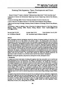
Fig. 1: Concept and realization of the proposed system. a) Conception and physical implementation, depicting the stack system
design, the rotating platform and the static transmitter coil. b) Block diagram of the system. c) Schematic of the wireless power transfer, rectification and DC-DC conversion. a transistor is periodically switched with the frequency of operation. Using only a few components (L1, C1, L2, C2), a sinusoidal output voltage at the load is generated (see Figure 2 (a)), while current and voltage waveforms over the transistor do not overlap, leading to vanishing switching loss. Using the equations from Sokal et.al. 7 , it is possible to design the amplifier to achieve target criteria, such as required output power, desired load resistance, or specific component values. The power is subsequently transferred between two inductively coupled coils. The stationary coil is placed under the rotating disk. The wireless power transfer module (WPT) schematic is shown in Figure 1 (c). After the receiver coil, the AC power is rectified. A DC-DC converter after the rectification stage is connected to the rotating coil. The DC-DC converter provides a 5 V supply for the µC and the sensors and actuators. The efficiency of wireless power transfer between inductively coupled coil pairs decreases rapidly with increasing separation 9 (see Figure 2 (b)), but for a rotating disk platform, the distance between the coil pair can be kept small enough to achieve acceptable transmission efficiency. To characterize the power transmission capabilities of the entire system, the output voltage on the disk after the DC-DC converter was measured for varying load resistance. A power of 2.4 W was measured after the linear regulator, so this is the maximum power available on the current disk (see Figure 3). Only 1 W in output power is measured when the linear regulator is replaced by a switching DC-DC converter (LT3470), due to its maximum output current limitation of 200 mA. The DC-DC converter has to be chosen according to the actual power consumed on the disk. While linear regulators are easy to implement and only need few components they are ineffi2|
1–4
Fig. 2: a) Schematic of the implemented class E amplifier. In-
set: measured voltage waveform of drain to source (VDS ) and gate to source (VGS ). b) Measured power transmission efficiency between the two coils as a function of their separation. At a minimum distance of 2.6 mm due to the physical configuration, the power transmission efficiency between the coils is 86%.
cient if the input voltage or output current of the regulator are high, which leads to additional heat on the disk that is potentially undesired. On the other hand, switching DC-DC converters are highly efficient devices, however, in general they require more components and a more complicated circuit layout. The load regulation of the system can be observed in Figure 3. We measured a system efficiency of 40% at a maximum power of 1 W with the switching DC-DC converter and 30% with the linear regulator at 2.4 W. Having available a con-
14 a) Rectifier. b) Switching DC-DC converter.
12
c) Linear regulator.
Voltage / V
d) Online measurement. 10
8
6
4
2
0,0
0,1
0,2
0,3
0,4
0,5
Fig. 4: a) Standard Arduino-micro board: 48 mm×18 mm. b)
Custom Arduino-micro, rearranged on a disk: 50 mm . interface design in a number of useful configurations, and a cross-platform software development environment. The software is designed to provide the programmer with a simplified command set, which allows programming without the need to learn the internal specifications of the µC. The hardware setup used in this paper is based on the Arduino micro board featuring an ATMega32UA µC (16 MHz clock, 8 bit CPU, 32 I/O pins, 8-channel 10-bit A/D converter, 4.5 − 5.5 V supply). The schematic of the standard board, available in the public domain, was rearranged to fit our application (see Figure 4).
Current / A
Fig. 3: Load regulation of the entire system for different con-
figurations. a) only with a rectifier, b) with a switching DCDC converter with a maximum output current of 200 mA, c) with a linear regulator, d) online power measurement on the disk during spinning with switching DC-DC converter. stant power supply on the rotating system greatly increases the flexibility of a Lab-on-a-disk system. Not only can electrically driven sensors and actuators be used, but furthermore, a µC can be powered, which allows for control loops, monitoring, and communication to be implemented. The choice of the µC should fulfil the following criteria: • Low power consumption. This is due to the constantly available but still limited amount of power on the disk. • Reasonable clock speed. Real-time applications require fast response times, especially when microfluidics is involved, so that at least µs clock speeds are necessary. • A reasonable number and type of I/O ports. With 5 to 10 I/O ports, a large number of signals can be read and written, and if more are needed, port expanders can be used. An I2 C and SPI Bus greatly simplifies system design and opens up the platform for a range of commercially available subsystems. • Easy of programming and use. Since typical users will not be experts in microelectronics or programming, an intuitive interface is needed. The Arduino open hardware platform 10 currently fulfils these criteria. It is based on an Atmel µC, a standardized hardware
Table 1: Possible improvements of reported Lab-on-a-disk applications by using subsystems of the modular platform. (For more details see Potential applications section) Reference
µC
Storage
Sensors
Actuators
M. Amasia 11 M. Glynn 12 B. Lee 13 N.Kim 14 Y.Kim 15
+ ++ + ++ +++
+ + + + ++
++ +++ ++ ++ ++
+++ ++ +++ +++
In order to demonstrate the flexibility and capabilities of the platform, a modular plug-and-play and therefore non-compact design was chosen that facilitates rapid prototyping, rather than focusing on a specific application, for which a more compact design could have been manufactured. The rotating system consists of six disks (see Figure 1 (a) for an overview), containing several sensors (gyroscope, temperature, pressure), two actuators (fan and motor), seven LEDs, a bluetooth module and an SD-card reader in addition to the µC. The system functionality is characterised by exemplary measurement curves shown in Figure 5. The received power is monitored over time for three different resistive loads in Figure 5 (a). Figure 5 (b) plots temperature and angular velocity over time, as measured by sensors on the disk. By activating all components of the system, 0.7 W of power was consumed. While the last paragraph demonstrated the system capabilities of the platform in principle, the following focuses on the opportunities that emerge for reported applications. 1–4 | 3
spinning. Y. Kim et al. 15 report on a new robust and reliable way to dynamically control laminar flow interfaces for very long time periods. With active control on the disk this could be implemented on Lab-on-a-disk devices.
Conclusions and Outlook
Fig. 5: Example of online measurable physical variables in
the proposed rotating system. (a) Received power at 3 different loads with a switching DC-DC converter (LT3470). (b) Logged temperature and angular velocity ω of the disk. ω was obtained by means of a gyroscope and from acceleration in the X and Y directions. At high enough rotation speed, the gyroscope signal saturated.
Potential applications Amasia et al. 11 report on integrating a PCR onto a fluidic disk. The heating and cooling of the reaction chamber was implemented using a large thermal block that was placed in close proximity under the rotating disk. A constant supply of power on the disk would facilitate integrating a thermoelectric element directly in contact with the fluidic disk and controlling and measuring it using the µC. This should allow for a more efficient and precise control of the temperature in the fluid with a much smaller thermal element. Glynn et al. 12 report the magnetic selection of cells by sorting these into separate compartments. The integration of logic and sensors allows a more quantitative detection by directly counting each bead. This can either be done with a light trap, or via impedance spectroscopy. Having the sensing elements at a fixed position, and close to the fluidic chamber, dramatically increases the sensitivity compared to usual disk setups. The second advantage is that, in contrast to detection from outside the disk, the beads move linearly (radially) relative to the on-disk detector. N. Kim et al. 14 present an automated microfluidic compact disk (CD) system specialized for cultivating and monitoring Caenorhabditis elegans. With active components on the disk, parameters such as temperature and the acting gravitational force could be monitored much more precisely. Also, an active sorting mechanism could be implemented that is then controlled by the µC. Lee et al. 13 report a fully integrated device that can perform both multiple biochemical analysis and sandwich type immunoassay simultaneously on a disk. The capability of the ferro-wax valve platform would be greatly enhanced if these valves could be actuated while the disk was 4|
1–4
The presented approach opens the door to a much more direct and sophisticated system level toolbox for Lab-on-a-disk applications. The implementation of wireless constant power supply, communication, and control logic, together with sensing and actuation, combines stationary analysis and spinning fluidic disks towards the best of both worlds. In this paper we demonstrated the technical foundation of what we believe will have numerous applications in the future.
Acknowledgements This work was financed in part by the ERC Grant NMCEL (grant number 290586), and in part by an operating grant from the University of Freiburg. The authors express their gratitude to their colleague Nils Spengler who made available the ShareLATEX environment.
References 1 J. Ducr´ee, S. Haeberle, S. Lutz, S. Pausch, F. von Stetten and R. Zengerle, Journal of Micromechanics and Microengineering, 2007, 17, S103. 2 R. Gorkin, J. Park, J. Siegrist, M. Amasia, B. S. Lee, J.-M. Park, J. Kim, H. Kim, M. Madou and Y.-K. Cho, Lab Chip, 2010, 10, 1758–1773. 3 Z. Noroozi, H. Kido and M. J. Madou, Journal of The Electrochemical Society, 2011, 158, P130–P135. 4 K. Abi-Samra, T.-H. Kim, D.-K. Park, N. Kim, J. Kim, H. Kim, Y.-K. Cho and M. Madou, Lab Chip, 2013, 13, 3253–3260. 5 G. Wang, H.-P. Ho, Q. Chen, A. K.-L. Yang, H.-C. Kwok, S.-Y. Wu, S.-K. Kong, Y.-W. Kwan and X. Zhang, Lab Chip, 2013, 13, 3698–3706. 6 J. Burger, A. Gross, D. Mark, G. Roth, F. von Stetten and R. Zengerle, IR thermocycler for centrifugal microfluidic platform with direct on-disk wireless temperature measurement system, 2011, http://dx.doi.org/10.1117/12.887178. 7 N. Sokal and A. Sokal, Solid-State Circuits, IEEE Journal of, 1975, 10, 168–176. 8 Z. N. Low, R. Chinga, R. Tseng and J. Lin, Industrial Electronics, IEEE Transactions on, 2009, 56, 1801–1812. 9 C.-J. Chen, T.-H. Chu, C.-L. Lin and Z.-C. Jou, Circuits and Systems II: Express Briefs, IEEE Transactions on, 2010, 57, 536–540. 10 Arduino, http://www.arduino.cc. 11 M. Amasia, M. Cozzens and M. J. Madou, Sensors and Actuators B: Chemical, 2012, 161, 1191 – 1197. 12 M. Glynn, D. Kirby, D. Chung, D. J. Kinahan, G. Kijanka and J. Ducr´ee, Journal of Laboratory Automation, 2014, 19, 285–296. 13 B. S. Lee, Y. U. Lee, H.-S. Kim, T.-H. Kim, J. Park, J.-G. Lee, J. Kim, H. Kim, W. G. Lee and Y.-K. Cho, Lab Chip, 2011, 11, 70–78. 14 N. Kim, C. M. Dempsey, J. V. Zoval, J.-Y. Sze and M. J. Madou, Sensors and Actuators B: Chemical, 2007, 122, 511 – 518. 15 Y. Kim, B. Kuczenski, P. R. LeDuc and W. C. Messner, Lab Chip, 2009, 9, 2603–2609.