Electro-optic thin films of organic nonlinear optic molecules aligned through vacuum deposition Weiwei Sun,1,2 Zhaohong Wang,1,4 Antao Chen,1,2,* Ilya Kosilkin,3 Denise Bale,3 and Larry R. Dalton2,3 1 Applied Physics Laboratory, University of Washington, Seattle 98105, USA Electrical Engineering Department, University of Washington, Seattle 98105, USA 3 Chemistry Department, University of Washington, Seattle 98105, USA 4 Key Laboratory of Physical Electronics and Devices of the Ministry of Education, Xi’an Jiaotong University, China *
[email protected] 2
Abstract: Nonlinear optical molecules can be vacuum deposited into uniform thin films using thermal evaporation. Alignment order can be achieved during thin film deposition by an in-plane electrical field poling using electrodes patterned on the substrate. Electro-optic (EO) coefficients, r33 and r13 are independently measured using Young's interferometry technique. Thin-films of N-benzyl-2-methyl-4-nitroaniline (BNA) can exhibit an EO coefficient, r33, comparable to that of BNA single crystals. EO coefficients of BNA at different poling fields, wavelengths, and frequencies are investigated. © 2011 Optical Society of America OCIS codes: (190.4710) Optical nonlinearities in organic materials; (120.3180) Interferometry.
References and links 1. 2. 3. 4. 5.
6. 7.
8.
9.
10.
11. 12.
13.
D. Burland, “Optical nonlinearities in chemistry: introduction,” Chem. Rev. 94(1), 1–2 (1994). M. G. Kuzyk and C. W. Dirk, Characterization Techniques and Tabulations for Organic Nonlinear Optical Materials (Marcel Dekkar, 1998). T. A. Skotheim and J. R. Reynolds, Handbook of Conducting Polymers. Conjugated polymers: Theory, Synthesis, Properties, and Characterization, 3rd ed. (CRC Press, 2007). K. D. Singer, J. E. Sohn, and S. J. Lalama, “Second harmonic generation in poled polymer films,” Appl. Phys. Lett. 49(5), 248–250 (1986). T. D. Kim, J. W. Kang, J. Luo, S. H. Jang, J. W. Ka, N. Tucker, J. B. Benedict, L. R. Dalton, T. Gray, R. M. Overney, D. H. Park, W. N. Herman, and A. K. Jen, “Ultralarge and thermally stable electro-optic activities from supramolecular self-assembled molecular glasses,” J. Am. Chem. Soc. 129(3), 488–489 (2007). D. Rezzonico, S. J. Kwon, H. Figi, O. P. Kwon, M. Jazbinsek, and P. Günter, “Photochemical stability of nonlinear optical chromophores in polymeric and crystalline materials,” J. Chem. Phys. 128(12), 124713 (2008). H. Hashimoto, Y. Okada, H. Fujimura, M. Morioka, O. Sugihara, N. Okamoto, and R. Matsushima, “Secondharmonic generation from single crystals of N-Substituted 4-Nitroanilines,” Jpn. J. Appl. Phys. 36(Part 1, No. 11), 6754–6760 (1997). M. Fujiwara, K. Yanagi, M. Maruyama, M. Sugisaki, K. Kuroyanagi, H. Takahashi, S. Aoshima, Y. Tsuchiya, A. Gall, and H. Hashimoto, “Second order nonlinear optical properties of the single crystal of N-Benzyl 2-methyl-4nitroaniline: Anomalous enhancement of the d333 component and its possible origin,” Jpn. J. Appl. Phys. 45(11), 8676–8685 (2006). M. Fujiwara, M. Maruyama, M. Sugisaki, H. Takahashi, S.- Aoshima, R. J. Cogdell, and H. Hashimoto, “Determination of the d-tensor components of a single crystal of N-Benzyl-2-methyl-4-nitroaniline,” Jpn. J. Appl. Phys. 46(No. 4A), 1528–1530 (2007). K. Iwaszczuk, D. G. Cooke, M. Fujiwara, H. Hashimoto, and P. Uhd Jepsen, “Simultaneous reference and differential waveform acquisition in time-resolved terahertz spectroscopy,” Opt. Express 17(24), 21969–21976 (2009). K. Miyamoto, S. Ohno, M. Fujiwara, H. Minamide, H. Hashimoto, and H. Ito, “Optimized terahertz-wave generation using BNA-DFG,” Opt. Express 17(17), 14832–14838 (2009). S. Kalluri, S. Garner, M. Ziari, W. H. Steier, Y. Shi, and L. R. Dalton, “Simple two-slit interference electro-optic coefficients measurement technique and efficient coplanar electrode poling of polymer thin films,” Appl. Phys. Lett. 69(2), 275–277 (1996). P. Günter, C. Bosshard, K. Sutter, H. Arend, G. Chapuis, R. J. Twieg, and D. Dobrowolski, “2-cyclooctylamino-
#145322 - $15.00 USD Received 4 Apr 2011; revised 10 May 2011; accepted 11 May 2011; published 24 May 2011
(C) 2011 OSA
6 June 2011 / Vol. 19, No. 12 / OPTICS EXPRESS 11189
14.
15.
16.
17.
18.
5-nitropyridine, a new nonlinear optical crystal with orthorhombic symmetry,” Appl. Phys. Lett. 50(9), 486–488 (1987). O. P. Kwon, B. Ruiz, A. Choubey, L. Mutter, A. Schneider, M. Jazbinsek, V. Gramlich, and P. Gunter, “Organic nonlinear optical crystals based on configurationally locked polyene for melt growth,” Chem. Mater. 18(17), 4049–4054 (2006). R. P. Fraser, H. Sun, and P. Sullivan, “Use of spatially anisotropic intermolecular interactions to define order in molecular films grown by physical vapor deposition (PVD),” in Photonics, CMDITR Review of Undergraduate Research, Vol. 6, (2009). C. Hunziker, S.-J. Kwon, H. Figi, F. Juvalta, O.-P. Kwon, M. Jazbinsek, and P. Günter, “Configurationally locked, phenolic polyene organic crystal 2-{3-(4-hydroxystyryl)-5,5-dimethylcyclohex-2enylidene}malononitrile: Linear and nonlinear optical properties,” J. Opt. Soc. Am. B 25(10), 1678–1683 (2008). O. P. Kwon, S. J. Kwon, H. Figi, M. Jazbinsek, and P. Günter, “Organic electro-optic single- crystalline thin films grown directly on modified amorphous substrates,” Adv. Mater. (Deerfield Beach Fla.) 20(3), 543–545 (2008). J. L. Oudar and D. S. Chemla, “Hyperpolarizabilities of the nitroanilines and their relations to the excited state dipole moment,” J. Chem. Phys. 66(6), 2664–2668 (1977).
1. Introduction Organic electro-optic (EO) materials have been actively researched for decades for a broad range of electro-optic device applications [1–3]. The driving force of this research is primary due to the inherently large EO coefficients achievable with organic materials, along with their low dielectric permittivity, which makes them suitable for high bandwidth devices. The EO effect of these materials arises from the second-order nonlinear optic (NLO) molecules (dipolar chromophores) preferentially aligned in one orientation. The molecules must have overall noncentrosymmetric alignment for the macroscopic EO effect to occur. The most common organic EO materials are EO polymers, where the nonlinear optic molecules are imbedded in a passive polymer matrix. The alignment of the NLO molecules is typically achieved by electric field poling. In classical poling processing methods [4], the EO polymer film is heated close to its glass transition temperature while applying a DC electric field. The poling results in statistical polar orientation of the molecular dipoles along the field direction, with the order being maintained when the film is cooled down to room temperature with the poling field on. EO coefficients greater than 300 pm/V have been achieved in EO polymers [5]. However, EO polymer materials have limitations. Specifically, the loading density (concentration) of the NLO molecules in the polymer host is usually limited to less than 25% by weight. Some device designs are not compatible with solvent processing required in the fabrication of EO polymer thin films as well as the high temperature during the poling; thus, a dry (e. g. vacuum deposition) process to fabricate thin films of organic EO materials is preferred in this case. Organic EO crystal materials have properties complementary to EO polymers and neat thin films. One primary difference is that organic EO crystals have highdensity chromophore packing and excellent orientation stability up to the melting temperature of the material. EO crystals also have much better photostability than EO polymers [6]. For these reasons a vacuum deposition process to achieve thin films of organic EO materials that tend to form non-centrosymmetric crystals merits exploration. In this paper, a method of fabricating organic EO thin films through simultaneous thermal evaporation/deposition and electric-field poling is presented. Polycrystalline thin films of small angle domains are achieved. EO coefficients of thin films of N-benzyl-2-methyl-4nitroaniline (BNA) measured using a patterned substrate and Young's interferometry technique exhibited high EO coefficients that are comparable to those of bulk single crystals. EO coefficients of BNA were investigated at multiple wavelengths, different applied DC voltages during deposition, and measurement frequencies. 2. EO material and test sample fabrication The chemical structure of BNA is shown is Fig. 1(a) [7]. Similar to other common secondorder organic NLO molecules, it has a permanent dipole moment because the electron
#145322 - $15.00 USD Received 4 Apr 2011; revised 10 May 2011; accepted 11 May 2011; published 24 May 2011
(C) 2011 OSA
6 June 2011 / Vol. 19, No. 12 / OPTICS EXPRESS 11190
donating group and electron accepting are located at separate ends of the molecule. BNA is a solid crystal at room temperature, with a melting point of 105 °C at normal atmospheric pressure [7], and is one of the second-order NLO molecules that can form noncentrosymmetric single crystal from melt [8]. It has a relatively large nonlinear optical coefficient d333 of 234 ± 31 pm/V (r33 of 45 ± 6 pm/V) at the wavelength of 1064 nm [9]. The NLO properties of BNA and its application in THz radiation and EO waveguide modulators are areas of active research [8,10,11]. Samples consisted of glass substrates featuring a two-slit electrode design [12] (see Fig. 1(b) and Fig. 2). The electrodes were made of titanium with standard photolithography and lift-off processes. Titanium was used for its good adhesion to glass. The slit widths were patterned to be 5-20 μm with a center-to-center separation of 100 μm. Electrical connections to the lectrodes were made with wires attached to the electrodes with a conductive epoxy.
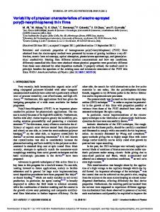
Fig. 1. (a) The chemical structure of BNA; (b) Schematic side view of the sample.
A DC voltage was applied across the slits of the electrodes during the deposition of BNA using thermal evaporation method. Figure 2(a) shows the connection of the DC voltage during the material deposition. The voltage across the slit creates an electric field that is perpendicular to the slit in the plane of substrate. An ammeter is used to detect electric breakdown during deposition. The breakdown voltage during thin film deposition was found to be above 10 V/μm and it mainly depends on small protrusions in the roughness of the edges of the electrodes as well as the dielectric strength of the deposited material. By using a coplanar electrode configuration and electric field direction mentioned above, a torque would be produced on the dipolar BNA molecules in the two slits to align them perpendicular to the slits in the plane of the substrate. The deposition was carried out using a thermal evaporator with base pressure of 5 × 10 6 Torr. BNA was evaporated from a thermal heater source. The deposition rate was kept below 1 nm per second by controlling the temperature of the evaporation source. BNA begins to evaporate at 70 °C, and the deposition rate increases with temperature. The deposition temperature for the desirable deposition rate was found to be 98 °C and resulted in an 800 nm thick BNA thin film after approximately 1 h. The glass substrate was not heated and remained at room temperature during deposition. Because of the low evaporation temperature of the BNA and the low pressure of the vacuum, heating the substrate was found to impair film growth. Specifically, no thin film of BNA forms on the substrate at substrate temperatures above 60 °C. Without heating the substrate, the thin film can be achieved in a uniform coverage on the substrate. During the deposition, BNA in the two slits crystallized in small angle domains with the polar axis aligned under the electrostatic force of the electric field. A scanning electron microscopy (SEM) image that shows the BNA thin film around one slit is shown in Fig. 3. The film in the image covered the edge of one slit, depicted with a dash line. The slit is on the left hand side of the line. It’s clearly shown that the BNA crystal domains in the slit are well aligned along the E-field, while the crystal domains outside the slit are orientated perpendicular to the electrode metal because the E-field is perpendicular to the electrode surface. Although the polycrystalline structure of the BNA thin film is expected to
#145322 - $15.00 USD Received 4 Apr 2011; revised 10 May 2011; accepted 11 May 2011; published 24 May 2011
(C) 2011 OSA
6 June 2011 / Vol. 19, No. 12 / OPTICS EXPRESS 11191
increase the scattering loss, the polycrystalline EO thin film can still be useful in device designs that are tolerant to material loss, such as spatial light modulators and silicon photonic crystals where long (centimeters) optical path lengths are not needed. The Young’s interference fringes from two-slit electrodes covered with a BNA thin film were clean and showed no noticeable effect of scattering.
Fig. 2. Top view of the sample substrate, with the polarity of voltage connection across the slits during the deposition and EO measurement indicated. (a) DC electric field is applied across the slits when EO material is thermally evaporated on the sample; (b) AC electric field is applied during the measurement of EO coefficients.
Fig. 3. The SEM image of BNA thin film around the slit.
3. EO measurement based on Young’s interference An EO measurement setup based on Young’s interference [12] was used to measure the EO coefficients reported here. Figure 4 illustrates the measurement device and signal processing. A photodetector was mounted on a translation stage, thereby allowing for it to move across the interference fringes to measure the fringe pattern and its modulation when an AC voltage is applied across one slit. The output from the detector was connected to the data acquisition (DAQ) module to record the average DC signal, and also to a lock-in amplifier to extract the AC modulation. When an electric field is applied across one slit (Fig. 2(b)) containing the material deposited, the Young’s interference pattern will shift laterally due to the change of refractive index in the BNA in one slit. If an AC field is applied, the pattern will spatially oscillate at the same frequency as the AC field. The oscillation can be detected as intensity modulation if the detector is positioned on the slope of fringe. Then EO coefficient could be calculated from AC signals and the intensity distribution of the fringe pattern. In our case the modulating AC field is in the same direction as the polar axis of the micro-domains of the BNA. The EO
#145322 - $15.00 USD Received 4 Apr 2011; revised 10 May 2011; accepted 11 May 2011; published 24 May 2011
(C) 2011 OSA
6 June 2011 / Vol. 19, No. 12 / OPTICS EXPRESS 11192
coefficient r33 was measured with polarization of the laser light parallel the electric field, while r13 was measured with polarization perpendicular to the electric field.
Fig. 4. EO measurement setup.
Based on the detected AC signal and the interference intensity of the fringe, the EO coefficients (r33 or r13) can be calculated via [12]
r
2Vac , n3 EtkL
(1)
where E is the electric field applied across one of the two slits; n is effective refractive index of the material; t is the deposited film thickness; λ is the wavelength of the incident beam; and L is the fringe period. Vac is the AC signal measured by a lock-in amplifier, and k is slope of the fringe at the position of measurement.
Fig. 5. Measured DC and AC signals detected across several fringes.
During the measurement, the detector is slowly scanned across the interference pattern. Figure 5 shows the DC and AC signals acquired during a scan. The x-axis of Fig. 5 is the detector position. The total range of scan covers several fringes. DC signal (solid line) represents the intensity of interference fringe, and AC signal (dotted line) represents the intensity modulation caused by the transverse oscillation of the fringe due to the applied modulating voltage. The AC signal is proportional to the first order derivative of the DC signal, and the EO coefficient can be calculated from Eq. (1) if the film thickness, index of refraction, slit width, AC modulating voltage, the first order derivative of the DC signal and the wavelength of the measurement are known. The error of measurement comes mostly from
#145322 - $15.00 USD Received 4 Apr 2011; revised 10 May 2011; accepted 11 May 2011; published 24 May 2011
(C) 2011 OSA
6 June 2011 / Vol. 19, No. 12 / OPTICS EXPRESS 11193
the measurement error of the film thickness. The thickness was measured with an optical profiler at the flat areas adjacent to the slits. However, from SEM images of the cross-section of the samples, the film thickness in the slot is found to be different from the film thickness in the flat areas by as much as ±25%. Errors from other sources are estimated to be about 5%. 4. Result and discussion Several materials, including BNA [7], COANP [13], DAT2 [14], PS1 [15], JD2112 [15], JD2116 [15], OH1 [16], EHD-1-12 [17] and EHD-1-13 [17] were examined. Among these materials, thin films of BNA were found to exhibit the highest EO coefficient. Properties of BNA thin films were further studied in detail, including the effect of poling field, dispersion of the EO coefficient, variation of the EO coefficient at different modulation frequencies and modulation voltages. The EO coefficient r33 of BNA thin films at different poling electric field is shown in Fig. 6(a). Due to the breakdown limitation, the highest electric field for BNA sample was kept under 10 V/μm. The poling electric field was varied from 3 V/μm to 10 V/μm. The measured r33 at 1550 nm was proportional to the poling filed, which compares with the linear relationship between r33 and poling field in poled EO polymers [12].
Fig. 6. The r33 coefficient as a function of electric poling field and as a function of wavelength. (a) The r33 coefficient as a function of electric poling field at the measurement wavelength of 1550 nm; (b) Theoretical and experimental results of EO coefficient r33 at different wavelengths.
The ratio between EO coefficients r33 and r13 was found to be about 4.8 at a typical field of 10 V/μm. The results also show that BNA thin films made under a high poling electric field have r33 values comparable to the BNA single crystal grown from solution [8], which has an r33 of about 45 pm/V at 1064 nm [9]. The dispersion of r33 of BNA was measured using three laser wavelengths: 980 nm, 1310 nm and 1550 nm, respectively. The BNA sample was 800 nm thick and prepared using an electric poling field of 10 V/μm. It was tested with a modulation voltage of 5 V and frequency of 1 kHz. The r33 values at measurement wavelengths are overlaid with a theoretical curve as shown in Fig. 6(b). The theoretical data was calculated from the dispersion of molecular first hyperpolarizability based on a two-level model [18] and was found to agree well with experimental data. Figure 7(a) shows the measurement results of the EO coefficients under different modulation frequencies. In the range between 200 Hz and 2 kHz, r33 remains constant. This indicates that molecular rotational motion does not have significant contribution to the EO coefficient, otherwise a roll-off of r33 should be observed over this frequency range.
#145322 - $15.00 USD Received 4 Apr 2011; revised 10 May 2011; accepted 11 May 2011; published 24 May 2011
(C) 2011 OSA
6 June 2011 / Vol. 19, No. 12 / OPTICS EXPRESS 11194
Fig. 7. EO coefficient r33 under different modulation frequencies and different modulation voltages. (a) EO coefficient r33 under different modulation frequencies; (b) EO coefficient r33 under different modulation voltages.
Figure 7(b) shows the results of the r33 measured at different modulation voltages. AC modulation voltages of 1 kHz modulation frequency were applied across a 20 μm slit, and r33 values were measured at five different AC amplitude voltages of 1 V, 2 V, 3 V, 4 V and 5 V, respectively. The detected modulation intensity at 1 kHz was found to be linear with applied field. The fact that the EO modulation is independent of the applied voltage suggests that the modulation is due to the linear EO effect and the contributions of higher order (e.g., Kerr) EO effects are negligible. 5. Conclusions By applying an in-plane electric field using electrodes fabricated on the substrate, BNA molecules deposited on the substrate through thermal evaporation can be aligned to form a polycrystalline thin film of small angle domains. Two-slit electrodes pattern on the glass substrate allows the molecules deposited in the slits be aligned by the electric field, and the EO coefficient measured by Young’s interferometric method. A linear relationship between the alignment field and EO coefficient has been observed, similar to the linear relationship observed in EO polymers. The EO coefficient of BNA thin films fabricated using this technique is comparable to that of single crystalline BNA. The dispersion of EO coefficient agrees with the theoretical dispersion of the first order hyperpolarizability. Because no roll-off of the EO modulation was observed below kilohertz frequencies, the electric field induced rotational motion of molecules does not have appreciable contribution to the EO coefficient. Acknowledgment We would like to express our appreciations to Emily A. Hillenbrand for synthesis and purification of EHD-1-12 and EHD-1-13 ingredient. We are also grateful to financial support by NSF Grant Number ECS-0437920, NSF-DMR-0092380, and NSF Center on Materials and Devices for Information Technology Research (CMDITR), Grant Number DMR-0120967.
#145322 - $15.00 USD Received 4 Apr 2011; revised 10 May 2011; accepted 11 May 2011; published 24 May 2011
(C) 2011 OSA
6 June 2011 / Vol. 19, No. 12 / OPTICS EXPRESS 11195