programs for producing drinking water that meets the USEPA safe drinking water act regulations. Ion exchange technology typically requires chemicals for the ...
Twelfth International Forum On Electrosynthesis In The Chemical Industry: Clean And Efficient Processing Sheraton Sand Key, Clearwater Beach, FL October 11-15, 1998
Electrochemical Reduction Of Nitrate Jerry J. Kaczur
Olin Corporation Chlor Alkali Products Division Charleston Technology Center P.O. Box 248 1186 Lower River Road Charleston, TN 37310 ABSTRACT Olin has developed an electrochemical reduction technology that provides an ecological method of treating aqueous streams containing oxyhalide and/or oxynitrogen chemical species with the co-production of little or no hazardous effluent waste.(1-3) This electrochemical technology, named ElectroReduction™, can efficiently reduce various oxychlorine DBP’s (Disinfection By-Products) species, such as chlorite (ClO2-) and chlorine dioxide (ClO2), formed from chlorine dioxide treatment of drinking water to environmentally safe chloride (Cl-) ions. The reduction technology can also be used to reduce oxynitrogen species present in water, such as nitrates (NO3-) and nitrites (NO2-), reducing them to nitrogen using suitable cathode materials. The ElectroReduction™ process utilizes a high surface area cathode structure design to obtain high oxy-specie removal efficiencies in single or multiple passes through the electrolytic system.
-1-
The selection of cathode materials for the process is important in maximizing the reduction of the specific oxychlorine and oxynitrogen anion species present in water while achieving high operating electrolytic current efficiencies. Bench scale testing of the reduction process has been demonstrated for the reduction of chlorite, chlorate, hypochlorite, and nitrate anions. The technology may be useful in pointof-use systems or for municipal drinking water treatment. Applying this technology for treating large quantities of water, such as in municipal water systems, will require further engineering design and scale-up. The reduction process can be applied to the treatment of dilute or concentrated chemical process waste streams. Information on oxynitrogen reduction chemistry as well as bench scale performance data in treating aqueous solutions containing nitrate as an oxynitrogen specie example is detailed in this paper.
application and yet must be as environmentally sound as possible.
1.0 INTRODUCTION Chemical oxidants such as chlorine, sodium hypochlorite, chloramine, chlorine dioxide, and ozone are widely used in the disinfection of drinking water for public protection against toxic microbial pathogens in the water. All of these oxidants produce various chemical disinfection by-products (DBP's) in the treated water that may pose potential health risks depending on their types and concentrations. Oxyhalide DBP's such as chlorite (ClO2-) and chlorate (ClO3-) ion species are present or formed with the application of chlorine dioxide, chlorine, or sodium hypochlorite oxidants in treating the water. Additionally, ground and surface waters used for drinking water can also contain oxynitrogen compounds, such as nitrates and nitrites. These compounds may come from a variety of sources such as agricultural runoff and fertilizers, chemical process effluents, acid rain, and from naturally occurring sources such as mineral deposits. The maximum contaminant level (MCL) allowable of combined nitrate/nitrite anions in drinking water in the United States was lowered by the USEPA from 50 mg/L down to 10 mg/L as N (nitrogen) in 1991. The rule was based on preventing methemoglobinemia in infants.(4) Similar total nitrate/nitrite contaminant limits are also in effect in Europe.(5) Various technologies can be used in removing of these oxyhalide and oxynitrogen species from water. These technologies include biological methods, membrane based separation methods such as reverse osmosis, nanofiltration, and electrodialysis, in addition to ion exchange, chemical reduction, and physical adsorption methods. Many of these technologies present some hidden or not so well defined process problems. These may include the need for a large capital outlay for installation or high operating costs for the removal system. Other problems include the formation of by-product chemical waste streams from the use of any regeneration chemicals required or the production of concentrated waste streams containing the oxy-species that will require further treatment or disposal. The appropriate removal technology must be chosen to meet the particular needs of each process
Olin has developed two electrochemical reduction processes suitable for the removal/reduction of aqueous:
Oxyhalide species, in particular oxychlorine species such as chlorite (ClO2-) and chlorine dioxide (ClO2), to environmentally safe chloride (Cl-) ions.(1,3)
Oxynitrogen species, such as nitrate (NO3-) and nitrite (NO2-) to environmentally safe nitrogen.(2,3)
These electrochemical reduction processes, collectively named ElectroReduction™, are useful for the removal/reduction of oxychlorine and oxynitrogen species present in potable water or in other chemical process and waste effluent streams. These oxy-species are reduced using an electrochemical system employing high surface area cathode structures in special electrochemical cell designs. Either dilute or concentrated solutions of these oxyspecies can be efficiently reduced in the process. The process can be operated in either single pass or multiple recycle through the reduction system to achieve the desired concentration level of oxy-species in the final treated water. This paper reviews the chemistry of nitrogen electrochemical reduction and presents some data obtained in bench scale tests in nitrate reduction. Alternative nitrate removal technologies are also briefly reviewed.
2. NON-ELECTROCHEMICAL NITRATE REMOVAL/REDUCTION PROCESSES Non-electrochemical technical approaches in reducing or removing nitrates and nitrites from aqueous water streams can be divided into biological and chemical reduction processes. These processes include biological anaerobic digestion, ion exchange, reverse osmosis, chemical reduction, and distillation. Some of these are briefly described in this section.
2.1 Biological Reduction
-2-
Ion exchange methods are very effective in the removal of nitrate and nitrite anions from aqueous process streams. Various ion exchange resins have been developed with a high specificity for theses anions. This technology is being evaluated in various test programs for producing drinking water that meets the USEPA safe drinking water act regulations.
Anaerobic biological processes for the destruction or removal of nitrates in industrial and municipal waste water treatment processes is widely practiced. These processes can be slow, requiring system retention times ranging from days to weeks. These process systems can also require a large investment in land and/or capital in equipment such tanks and pumps depending on the volumetric capacity and complexity of the system. One commercial example of groundwater denitrification is NSW Corporation, which markets a rotating biocontactor that can reduce nitrates present in a groundwater, potable water supply from 60 mg/L to 5 mg/L.(6) Biological denitrification pilot trials are being conducted for evaluating nitrate removal in drinking water treatment. This type of process is particularly favored in Europe. In the United States, the emphasis has been in developing ion exchange processes. This is because ion exchange is considered a simple, rugged, and effective process that has a relatively low cost. In one denitrification pilot study, biologically activated filters using denitrification bacteria and methanol as a reductant feedstock for the bacteria was evaluated for nitrate/nitrite removal performance in drinking water treatment.(7,8) The pilot system used a biological fluidized bed having a capacity of 40 m3/hr of water. A 70 mg/L nitrate influent concentration was reduced to between 2 - 17 mg/L total nitrate/nitrite depending on the specific operating conditions. The process product stream contained excess methanol reductant as well as nitrite, which was found to be an intermediate reduction species. Biological reduction methods have some major drawbacks. The added methanol reductant must be fully consumed, otherwise it will be converted into additional DBP’s in the water if chlorine is used to provide the disinfectant residual in the finished water. These DBP’s are THM’s, Total Trihalomethanes, which are chlorinated organics. In addition, there are concerns as to the potential health risks related to the toxicity of small concentrations of methanol in the finished product drinking water. Other less toxic reductants are being evaluated in Europe. 2.2 Ion Exchange/Membrane Processes
Ion exchange technology typically requires chemicals for the periodic regeneration of the various ion exchange resin(s) employed. This can generate a chemical waste stream in addition to producing a concentrated nitrate/nitrite containing by-product stream, both of which can create further pollution and waste disposal problems. Other important issues with ion exchange processes are biofouling of the resins as well as the accumulation of metals in the resins. One nitrate removal ion exchange process was piloted with the potential capability of producing a land disposable regenerant from the system. (9) The process used a two bed ion exchange process consisting of a strong acid cation bed exchanger and a weak base anion bed exchanger that was arranged in series. Ammonium hydroxide and nitric acid were tested as regenerants. These streams, when combined, produced an ammonium nitrate solution effluent for use as a fertilizer. The piloting showed problems in regard to cation bed fouling by calcium and transition metal ions. In addition, the high cost of nitric acid as the acid regenerant and problems with anion bed exhaustion by sulfate ions made the system cost prohibitive. In another recently piloted ion exchange approach, a single, strong base anion exchanger is used for nitrate ion removal and is regenerated using a sodium chloride brine solution. The brine regenerant effluent stream containing nitrate is then treated in a separate anaerobic system with added methanol and other nutrients for the bacteria. The denitrated brine solution is then mixed with additional NaCl make-up as needed and reused as the ion exchange regenerant.(9)
2.3 Chemical/Catalytic Reduction Processes
-3-
A German study compared the costs of RO versus electrodialysis for reducing nitrate in well water to produce suitable quality drinking water.(13) The conclusions of the study were that both processes had treatment costs that were nearly identical, so long as the concentrates could be discharged without cost and that water losses were unimportant. RO showed simplicity and high reliability where a pilot system operated for more than 27,000 hours without a noticeable decrease in salt selectivity. Electrodialysis had an advantage over RO where a high recovery of water was essential.
Recent chemical and catalytic processes have been described in the literature for removing nitrate/nitrite from aqueous process streams. Several examples of these processes are briefly described below. U.S. Patent 4,990,266 describes a chemical method for nitrate/nitrite removal utilizing a catalytic hydrogenation reduction process. Hydrogen gas is used to chemically reduce a palladium/rhodium or a palladium/copper metal mixture in a catalyst bed. Water containing soluble nitrates/nitrites is pumped through the catalyst bed and is converted to nitrogen. The water feed in the process is maintained at a pH of 8 or less.(11) Another proposed nitrate chemical removal method from water uses aluminum metal powder as the reductant. The process was most efficient in a pH range between 9.5 - 10.25. Nitrate ions are reduced to nitrite, ammonia, and nitrogen. Ammonia is the principal reaction product (60% - 95%) followed by nitrogen and nitrite.(12) The estimated reagent consumption was 1.16 grams of aluminum per gram of nitrate converted to ammonia. Some basic issues with the process are the aluminum concentration in the final water and the narrow range of pH required for the process.
2.4 Reverse Osmosis/Electrodialysis Reverse osmosis, commonly referred to as RO, is capable of removing 90 – 95% of all oxynitrogen compounds such as nitrates in drinking water to permissible levels. The RO process uses membranes that are highly selective in rejecting inorganic dissolved salts. The selectivity depends on the pore size of the specific membranes used in the process. RO systems require water feed pressures in a range from 20 psig to as high as 1500 psig in order to drive water through the RO membrane to produce the purified product water. To prevent inorganic salt concentration polarization at the RO membrane surfaces, which results in high operating pressures, water must flow across the surfaces of the membrane to continually remove these concentrated salts. Typically, RO processes recover between 20 to 80% of the input water as a product. The rest of the water becomes a concentrated salt waste stream that must be purged or treated.
-4-
Electrodialysis presents a similar problem as with ion exchange - what to do with the concentrated waste stream, especially if the stream cannot be recycled back to a process or converted to another form useful such as nitric acid.
3. ELECTROCHEMICAL REDUCTION PROCESSES Over the years, various electrochemical reduction processes have been developed for oxy-specie removal from chemical product solutions, such as NaOH. Other processes were developed for the reduction of oxy-nitrogen species into useful co-products such as ammonia. This section describes some of these processes.
3.1 Other Electrochemical Reduction Processes In the past, the various electrochemical processes developed for specific oxy-specie reduction utilized electrolytic cell designs having:
Low surface area expanded metal or screen cathode structures constructed from various metals, graphite, or carbon
Cell designs with and without separators or membranes to separate the anode and cathode reaction products Many of these are patented processes. A brief summary for relevant ones for nitrate reduction are given below.
U.S. Patent 3,542,657 is an electro-chemical process for the treatment of alkali metal
hydroxide solutions, such as sodium hydroxide, containing nitrates/nitrites. Nitrates are reduced in an undivided cell using nickel anodes and cathodes. Ammonia and nitrogen gas are the main reduction products from the process.(14)
another electrolytic cell having multiple anode and cathode compartments.(18)
U.S. Patent 4,125,445 is a process for the electrolytic reduction treatment of industrial process waste water containing nitro and nitrate ester compounds. The undivided cell design uses alkaline feed solutions and a copper cathode in a batch process for reducing nitrate esters. The by-products from the reduction change during the reduction process, producing ammonia after 80% of the esters are reduced.(15) U.S. Patent 4,397,719 is a process for the electrochemical reduction of alkali metal nitrates and ammonium nitrate to the corresponding nitrites. The two compartment electrolytic cell design uses cathode and anode compartments separated by a cation membrane. Various materials are used as cathodes. The catholyte feed is kept at a pH of 4.0 or higher. The nitrite product, if a waste, is thermally decomposed to nitrogen by thermally decomposing the salts outside of the cell.(16) U.S. Patent 4,956,057 is a reduction process for the complete removal of nitrites and nitrates from aqueous solutions. The aqueous solution is fed into the cathode compartment of an undivided cell. The cathode product gas is a mixture of H2, NH3, NO, and N2O which passes through a catalyst bed where it reacts to produce nitrogen and water. No cathode materials or process operating conditions are disclosed in the patent.(17) U.S. Patent 5,306,400 is a process for the combined removal and destruction of nitrate ions. The electrolytic cell design consists of an anode compartment, a cathode compartment, and a center compartment containing an anion exchange resin. The center compartment is separated from the anode and cathode compartments by anion exchange membranes. Aqueous nitrate ion containing solution passes through the center compartment, capturing nitrate ions onto the anion resin. The nitrate ions then migrate towards the anode compartment. The nitrate ions are then subjected to consecutive reduction and oxidation reactions by recirculating the nitrate ions into the anode and cathode compartments or into
-5-
Hobbs and co-workers(19-21), at Westinghouse Savannah River, have developed a process for the direct reduction of nitrates and nitrites under alkaline conditions to produce a high concentration NaOH solution product with gaseous byproduct formation of NH3, N2O, N2, and H2 and with oxygen released from the anode reactions. The process was developed to process alkaline high level radioactive waste stored in large tanks at the Savannah River nuclear reprocessing site and convert the nitrates/nitrites to NaOH which could be recycled for processing radioactive materials at the site. Bench and pilot testing evaluated both divided and undivided cell configurations. The best results were obtained with a membrane divided cell using an anode made from nickel or platinum on titanium and with nickel cathodes with a current efficiency of about 60 – 70%. The product from the system was a 3 – 5 M NaOH solution. Los Alamos National laboratory has disclosed a process on an internet web site for the conversion of nitrates to nitrogen gas. The nitrate waste is passed through a metal packed bed for the conversion of nitrate to nitrite, and then is processed in a stirred chemical reactor with electrodes with the final product being nitrogen. No other information is available.(22)
4. ELECTROCHEMICAL REDUCTION CHEMISTRY This section is a brief review of the reduction chemistry of nitrogen and chlorine compounds with a graphical representation of the energy transitions between the various nitrogen and chlorine chemical species.
4.1 Inorganic Nitrogen Reduction Chemistry The reduction chemistry of inorganic nitrogen compounds is complex since it is known to exist in at least 10 oxidation states. Table I lists the oxidation states of the common nitrogen compounds which range from +5 to -3. Table II is a partial listing of the potential electrochemical reduction reactions of the nitrate anion in acidic media to various lower valence nitrogen species. The standard Eo reduction potentials of these reactions are also given.(23-24) Table III is a partial listing of the potential electrochemical reduction reactions of the nitrite anion in acidic media to various lower valence nitrogen species. The standard Eo reduction potentials of these reactions are also given.(23-24) Table IV is a listing of the potential electrochemical reduction reactions of the nitrous acid anion, which is the prevailing converted nitrite species in acidic media, to various lower valence nitrogen species. The standard Eo reduction potentials of these reactions are also given.(23-24)
convert oxynitrogen species in aqueous solutions to environmentally safe reduced compounds under specific operating conditions. The process can efficiently reduce concentration levels of oxy-nitrogen species ranging from ppm to very concentrated solutions in the weight percent range.
5.1 ElectroReduction™ Cell Design Figure 2 is a shows a general diagram of one of the ElectroReduction™ cell design configurations. This electrochemical design has an anolyte compartment, catholyte compartment, and a separator, preferably a cation exchange membrane, that divides the two electrode compartments. The cell employs a zero gap design where the anode and cathode are in direct contact with the cation exchange membrane to minimize cell voltage, which is especially important when the aqueous solution to be treated has a low ionic conductivity. The anolyte compartment uses an anode structure that has an oxygen-evolving type electrocatalyst coating. The anode reaction generates hydrogen ions and oxygen from the splitting of water:
All of the nitrate and nitrite reduction reactions in acid media consume differing amounts of hydrogen ions. Since the reactions consume hydrogen ions, the pH of the solution will increase during the reduction in the vicinity of the reduction electrode surfaces.
2H2O ---> O2 + 4H+ + 4e-
Figure 1 graphically shows the energy surface diagram for the various nitrogen chemical species as a function of their total free energy, expressed in Faraday-volts, as a function of pH. This is a useful method of visualizing the free energy changes between the various nitrogen species and is calculated using an oxygen reference.(25) The most stable chemical species are found at the two ends of the energy diagram, with ammonium ions at the lowest oxidation state and nitrate ions at the highest oxidation state. Nitrogen has a stability region which is seen as the valley between NH3OH+ and N2O.
(1)
Deionized water is supplied to the anode compartment to replace water lost by electrolysis and from transport with the hydrated hydrogen ions through the membrane into the catholyte compartment. Dilute non-oxidizable acids such as sulfuric acid can also be used in the anolyte to provide solution conductivity when required. The catholyte compartment consists of a porous, high surface area cathode structure and a cathode current distributor plate. High surface area cathode materials that have been used in the cell include:
Graphite felts, woven graphite cloths, and graphite/carbon reticulates
Non-sintered and sintered metal felts made from metal fibers, metal foams, and metallized polymeric substrates.
5. ELECTROREDUCTION™ TECHNOLOGY The aqueous solution stream containing the oxy-nitrogen species to be reduced is pumped upwardly through the high surface area cathode
The Olin ElectroReduction™ Technology utilizes an electrolytic cell to electrochemically
-6-
structure in a flow-by type configuration where all of the flow goes upwardly through the cross sectional thickness of the into the high surface area structure with very little bypass flow.
and oxychlorine specie removal efficiencies. Most of the tests were conducted using oxyspecie concentrations in the 100 mg/L range or less in a single pass through the cathode compartment.
Oxynitrogen species are electrochemically reduced on the cathode surfaces to lower valence nitrogen-oxygen intermediates, ending preferably as nitrogen. The process reduction current inefficiency is mainly due to the competing water reduction reaction at the cathode surface when there are insufficient chemical species to reduce or the applied electrode potential (or current density) is too high. The water reduction produces hydrogen as a by-product as given by the reaction: 2H2O + 2e- --->
H2 + 2OH-
(2)
The oxy-specie removal efficiency of the ElectroReduction™ process depends on a number of factors, some of which are:
Aqueous oxy-nitrogen specie solution pH and concentration.
Mass/volume flowrate through the high surface area cathode structure, which determines residence time and mass transfer within the electrode structure.
Cathode surface area and porosity, which determines the reduction voltage potential at the cathode surfaces at set operating current densities.
The number of electrons required for the reduction of each oxy-specie.
The electrochemical reduction performance characteristics of the selected cathode material.
During cell operation, deionized water was metered into the anolyte compartment and the oxy-specie containing solutions were fed into the bottom of the cathode compartment and exited out at the top in a single pass through the cathode compartment and collected for analysis. In the application of the technology for nitrate removal, the pH of the aqueous feed solution was found to be a critical factor in obtaining high nitrate ion removal percentages at high current efficiencies. The other critical factor was the selection of an effective reduction cathode material for nitrate, which in this case was found to be copper. Table V shows the test data on the single pass electrochemical reduction of a dilute nitrate ion aqueous solution containing 85 mg/L of nitrate ion dissolved in deionized water. The solution feedstock was adjusted to various pH values using sulfuric acid as indicated. The cathode was a high surface area copper felt cathode fabricated from 2.5 mil x 3 mil pure copper fibers having a 3.0 inch x 12 inch x 0.125 inch thickness when compressed into the cathode compartment of the cell. The assembled copper felt cathode had a calculated specific surface area of 74 cm2/cm3 with a feed cross section area of 2.42 cm2. The current was kept constant in this set of tests at 1.01 amperes and the feed solution flowrate through the catholyte compartment of the cell was varied as indicated. The product solutions were analyzed by ion chromatography (IC) for nitrate and nitrite ion concentrations. The cell voltage ranged from 2.44 - 2.49 volts. The power cost estimates per 1000 gal shown are calculated at a $0.055/kWh power rate. The current efficiency was calculated on the basis of the conversion of nitrate ion to nitrogen in an acid medium which takes 5 electrons.
5.2 Bench Scale ElectroReduction™ Of Nitrate – Low Concentration, Single Pass Performance Results A 0.0232 m2 projected membrane area prototype lab scale cell was used in developing the technology. Various high surface area cathode materials such as graphite felt, stainless 316L fiber felt, and copper fiber felt were evaluated for performance for both oxynitrogen
-7-
The IC analysis data given in Table V shows that nitrite is formed and present as an intermediate by-product of nitrate reduction under these process conditions. In addition, the product solution pH increased after
electroreduction processing, indicating the consumption hydrogen ions as expected in the cathodic nitrate and nitrite reduction reactions given in Tables II, III, and IV. The product solution pH increases because hydrogen ions are consumed in the reduction reactions, resulting in an excess of hydroxyl ions (OH-) at the cathode surface. This pH increase dramatically slows down the reduction of nitrate.
In additional bench scale experimental work, copper cathodes were found to provide the highest nitrate ion reduction efficiency. Graphite and stainless steel cathodes were found to not be as effective in nitrate reduction, but these tests were conducted on near neutral solutions. These and other candidate cathode materials for nitrate reduction will be tested in the future.
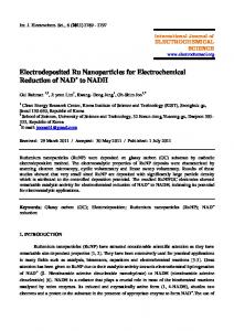
Figure 3 shows the nitrate removal percentage performance from the data in Table V as a function of the feed solution flowrate. As seen, the nitrate reduction removal efficiency dramatically increases as the solution feedstock solution is lowered from a pH of 7.60 to 2.26. Slower flowrates showed the highest nitrate removal percentages in the single pass flowthrough operation mode.
5.2 Bench Scale Batch ElectroReduction™ Processing Of High Concentration Nitrate Solutions A set of three experiments were conducted to determine the nitrate reduction efficiency for high concentration nitrate solutions and to determine the extent of by-product formation.
Figure 4 shows the reduction process current efficiency as a function of the solution flowrate and the initial pH values of the feedstock solution. The current efficiency more than doubles when the feedstock solution is reduced to a pH between 2 and 3 when operating at a specified flowrate. Figure 5 shows additional data not presented in any of the tables where a more dilute 10 mg/L nitrate solution in deionized water with a pH of 6.60 was passed through the cell cathode at a constant flowrate of 55 gm/min. The current was varied from 0.1 to 3 amperes. The nitrate percentage removal ranged between 10 - 28% and did not improve to any significant degree with increasing current over the range of the experiment. The pH of the product solutions increased with increasing current to a maximum value of 9.63. In our bench scale testing, nitrite was the only substantial chemical intermediate and byproduct found in the reduction of nitrate on a copper cathode substrate at sufficiently low pH process operating conditions. Ammonia and NO2 by-products were not detected in the product solutions, but formation of N2O, nitrous oxide (NO) may have been possible. Reactions (4) and (9) in Table II and reaction (13) and possibly reaction (12) in Table III are thought to be the predominant electrochemical reduction reactions for this reduction process configuration.
The set of three batch bench scale experimental test results are summarized in Table VI. The nitrate solutions were prepared from a potassium nitrate stock solution. A specific volume of the solution was continuously pumped through the catholyte and electrolyzed at the specified current densities in individual one hour batch runs. The solution pH was controlled in the specified pH range during the experiment with the addition of sulfuric acid. The 0.0232 m2 bench scale cell used in the single pass tests using a copper felt cathode was used in this set of tests. In Test #1, the operating pH of the system was allowed to vary between 1.5 – 3.5 during the run to help determine the formation of any intermediate gaseous or solution byproducts such as NO, N2O , or NH3 as a function of pH. Ammonia was noted in the catholyte off-gas and possibly NO when the solution input pH to the cell was allowed to increase into the 3 – 3.5 pH range. When the pH was lowered into the 1.5 – 2 range, ammonia was no longer detected by smell. The test results showed a 166% CE based on the reduction of nitrate to nitrogen which takes 5 electrons, indicating definitely that there were nitrate side reduction reactions that were requiring a lower number of electrons such as the formation of NO and N2O. Test #2 was conducted using a very high 123.2 gpl NO3- solution and the pH of the run was controlled in the pH 1 – 1.5 range. No ammonia smell was noted in the catholyte offgas during the test. The final CE of the run was 125%, indicating that there was still a small
-8-
amount of side reactions that were occurring, most probably the formation of N2O and maybe a small amount of NO.
species and percentage removal required.
Test #3 was conducted using a more dilute 22 gpl nitrate solution which dropped to a concentration of 4.4 gpl nitrate at the end of the run. . No ammonia smell was noted in the catholyte off-gas during the test. The CE dropped to an average of 47% for the test, indicating that hydrogen was being produced from the reduction of water.
8. REFERENCES 1.
2. 6. TECHNICAL CHALLENGES The ElectroReduction™ technology development for nitrate reduction will require scale-up of the technology to handle large flowrates - in the 50 to 1000 gpm range. We feel that the system can be successfully scaled-up but will require additional R&D for fabricating and evaluating several potential scale-up cell designs. In addition, the process development will require work in evaluating alternative cathode materials of construction to optimize nitrate reduction. The nitrate reduction products from the process will also need to be analyzed to quantify the amount of the various ionic and gaseous byproduct species.
3.
4. 5.
6. 7. SUMMARY In summary, the key features of the Olin ElectroReduction™ process are:
7.
An effective process for the removal/reduction of oxynitrogen and species from aqueous solutions. The main nitrate reduction product is environmentally safe nitrogen.
8.
Simple and safe, using the “electron” as the reducing agent.
Effective oxy-specie reduction in a single pass or multiple recycle/batch operation through the electrolytic system even down to low mg/L oxy-specie concentrations.
Low to moderate power costs in water processing depending on the oxy-
-9-
9.
Kaczur, J. J., Cawlfield, D. W., and Woodard, K. E., Jr., U.S. Patent 5,167,777, "Process And Apparatus For The Removal Of Oxyhalide Species From Aqueous Solutions", Issued Dec. 1, 1992 (to Olin Corporation). Kaczur, J. J., and Cawlfield, D. W., and Woodard, K. E. , Jr., U.S. Patent 5,376,240, “Process For The Removal Of Oxynitrogen Species From Aqueous Solutions”, issued Dec. 27, 1995 (to Olin Corporation). Kaczur, J. J. and Cawlfield, D. W., “Oxyhalide and Oxynitrogen Specie Removal From Aqueous Solutions by Electrochemical Reduction”, 8th Annual International Forum on Electrolysis in the Chemical Industry: Environmental Electrochemistry”, Lake Buena Vista, FL, Nov. 13-17, 1994. Phase II Final Rule. Federal Register, 56:20:3526 (Jan. 30, 1991). “Nitrate, Nitrate Everywhere”, Process Engr. Environ. Protection Suppl., No. 3, pp. 23-24 (1991). NSW Corporation, Environmental Systems, Roanoke, VA. Advertisement in J. Am. Water Works Assoc., 85:4, (1993). Liessens, J., Germonpré, R., Beernaert, S., and Verstraete, W., “Removing Nitrate With a Methylotrophic Fluidized Bed: Technology and Operating Performance”, J. Am. Water Works Assoc., 85:4, pp. 144-154, (1993). Liessens, J., Germonpré, R., Beernaert, S., and Verstraete, W., “Removing Nitrate With a Methylotrophic Fluidized Bed: Microbiological Water Quality”, J. Am. Water Works Assoc., 85:4, pp. 155-161, (1993). Clifford, D. A. and Weber, W. J. Jr., “A Nitrate-Removal Ion-Exchange Process With a Land-Disposable Regenerant”, Proc. National Conf. on Treatment and Disposal Of Industrial Wastewaters and Residues, Apr. 26-28, Houston, TX. (1977).
10.
11.
12.
13.
14.
15.
16.
17.
18.
19.
20.
21.
Clifford, D. and Liu, X., “Ion Exchange for Nitrate Removal”, J. Am. Water Works Assoc., 85:4, pp. 135-143, (1993). Vorlop, K-D., Tacke, T., Sell, M., and Strauss, G., U.S. Patent 4,990,266, “Process For Removing The Nitrite And/Or Nitrate Content In Water”, Issued Feb. 5, 1991 (to Umweltschutztechnologie mbH GUTEC: Gesellschaft zur Entwicklung von). Murphy, A. P., “Chemical Removal of Nitrate From Water, Nature, Vol. 350, Mar. 21, 1991 pp. 223-225. Patent applied for Aug., 1990. Rautenbach, R., Kopp, W., Opbergen, G. van, and Hellekes, R., “Nitrate Reduction of Well Water by Reverse Osmosis and Electrodialysis - Studies On Plant Performance and Costs”, Desalination, 65, pp. 241-258 (1987). Mindler, A. B. and Tuwiner, S. B., U.S. Patent 3,542,657, “Electrolytic Reduction Of Nitrate From Solutions Of Alkali Metal Hydroxides”, Issued Nov. 24, 1970 (to Hydronics Corp.). Hurley, E. K., U.S. Patent 4,125,445, “Electroreduction Of Nitrate Esters”, Issued Nov. 14, 1978 (to Hercules Inc.). Yoshida, M., U.S. Patent 4,397,719, “Process For Preparing Nitrogen By Ammonia Nitrate Decomposition”, Issued Aug. 9, 1983 (to Asahi Kasei Kogyo Kabushiki Kaisha). Stucki, S. and Winkler, D., U.S. Patent 4,956,057, “Process For Complete Removal Of Nitrites And Nitrates From An Aqueous Solution”, Issued Sep. 11, 1990 (to Asea Brown Boveri Ltd.). Bradbury, D. and Elder, G. R., U.S. Patent 5,306,400, “Method For The Combined Destruction Of Nitrate Ions”, Issued Apr. 26, 1994 (to Bradtec Limited). Hobbs, D.T and Ebra, M. A., “Electrochemical Processing of Alkaline Nitrate and Nitrite Solutions”, AIChE Symposium Series, No. 254, Vol. 83 pp. 149-155 (1987) Hobbs, David T., “Electrochemical Treatment of Liquid Nuclear Wastes”, 8th Annual International Forum on Electrolysis in the Chemical Industry: Environmental Electrochemistry”, Lake Buena Vista, FL, Nov. 13-17, 1994. Steimke, J. L., Hobbs, D. T., and Steeper, T. J., “Pilot Scale Testing of
- 10 -
22. 23.
24.
25.
Electrochemical Processes For Nitrate and Nitrite Destruction and Caustic Recovery”, 11th Annual International Forum on Electrolysis in the Chemical Industry: Electrochemical Processing Technologies, Sheraton Key Clearwater Beach, FL. , Nov. 2-6, 1997. Los Alamos National Laboratory, Internet Web Page, No other information available. Maloy, J. T., “Chapter 7. Nitrogen, Phosphorus, Arsenic, and Bismuth”, pp. 127 - 139, in Standard Potentials in Aqueous Solutions, edited by Bard, A. J., Parsons, R., and Jordan, J., Marcel Dekker, Inc., N.Y., (1985). Pourbaix, M. and Zoubov, N. de, “Section 18.1 - Nitrogen”, pp. 493 - 503, in Pourbaix, M., Atlas Of Electrochem-ical Equilibria In Aqueous Solutions, Trans. by Franklin, J. A., National Association Of Corrosion Engineers , Houston, TX (1974). Cawlfield, D. W., Unpublished work copyright ©1994, Olin Corporation.
TABLE I. Oxidation states of typical nitrogen compounds. Oxidation State +5 +4 +3 +2 +1 0 -1/3 -1 -2 -3
Typical Nitrogen Compounds HNO3 , NO3NO2 , N2O4 HNO2 , NO2- , NO+ , NCl3 NO N2O , H2N2O2 , N2O2-2 , NHCl2 N2 NH3 , N3NH3OH+ , NH2OH , NH2Cl N2H5+ , N2H4 NH4+ , NH3
TABLE II. Listing of potential nitrate ion reduction reactions in acidic media and their standard Eo reduction potentials. Reactions:
Eqn. No.
Nitrate Ion Reduction In Aqueous Acidic Media NO3- + 2H+ + e---> NO2(g) + H2O + 2e-
NO3-
+ 2H
NO3-
+ 10H + 8e+ 3H+ + 2e-
NO32NO3NO32NO3-
+ +
+ 10H + 8e+ 4H+ + 3e+
+ 12H
+
Standard Reduction Potential Eo in Volts
(3)
+0.78
+ H2O
(4)
+0.84
+ 3H2O
(5)
+0.88
---> HNO2 + 2H2O
(6)
+0.94
---> N2O(g)
(7)
+1.12
(8)
+0.96
(9)
+1.25
--->
NO2-
--->
NH4+
+ 5H2O
---> NO(g) + 2H2O + 10e ---> N2(g) + 6H2O
Table III. Listing of potential nitrite ion reduction reactions in acidic media and their standard Eo reduction potentials. Reactions:
Eqn. No.
Nitrite Ion Reduction In Aqueous Acidic Media NO2- + 2H+ + e---> NO + H2O NO22NO22NO2-
+ 8H
+ 6e-
+
+ 6H
+
+ 8H
+
+ 4e+ 6e-
Standard Reduction Potential Eo in Volts
(10)
+1.20
(11)
+0.90
---> N2O + 3H2O
(12)
+1.40
---> N2 + 4H2O
(13)
+1.52
--->
NH4+
+ 2H2O
- 11 -
TABLE IV. Nitrite ion is predominantly in the nitrous acid form in strong acid media. This table lists the nitrous ion reduction reactions in acidic media and their standard Eo reduction potentials. Reactions:
Eqn. No.
Nitrite Ion Reduction In Aqueous Acidic Media 2HNO2 + 4H+ + 4e---> N2O + H2O 2HNO2 + 4H
+
2HNO2 + 6H
+
2HNO2 + 6H
+
+ 2e+ 6e+ 6e-
---> H2N2O2 + 2H2O ---> N2(g) + 4H2O --->
NH4+
+ 2H2O
Standard Reduction Potential Eo in Volts
(14)
+1.30
(15)
+0.86
(16)
+1.45
(17)
+0.86
TABLE V. ElectroReduction™ test data for 0.0232 m2 bench scale cell treating an 85 mg/L nitrate ion feed solution in deionized water in a single pass through the cell at a constant current of 1.01 amperes. Feed solution was acidified to the various pH values as indicated and demonstrates the effect of feed/process pH on nitrate reduction efficiency. The cathode was an unsintered copper fiber felt specific surface area of approximately 74 cm2/cm3. Solution Feedrate (ml/min)
Cell Amps
Cell Volts
Product Solution pH
IC Analysis mg/L of:
Total % NO3-/NO2Reduction
% Current Efficiency
Est. Power $/1000 Gal @ $0.055/kWh
15.3 17.6 30.6 35.3
9.2 5.4 5.3 3.0
$0.159 $0.315 $0.547 $1.136
Initial Feed Solution Acidified To pH of 3.06 Using Conc. H2SO4: 55 1.01 2.45 3.85 60 9 18.8 27.8 1.01 2.45 5.75 44 13 32.9 16.0 1.01 2.45 6.50 30 13 49.4 7.7 1.01 2.45 7.14 7.1
$0.159 $0.315 $0.547 $1.136
Initial Feed Solution Acidified To pH of 2.26 Using Conc. H2SO4: 55.0 1.02 2.45 2.43 38 94%
>94%
85 mg/L NO3in Feed Solution
80
Feed Solution pH 7.60 pH 3.05 pH 2.26
60
40
20
0 0
10
20
30
40
Solution Feed Flowrate In ml/min
50
60 Slide 14
ElectroReduction™ Cell Nitrate Reduction Performance - Low Nitrate Concentration Soln's Electrochemical Nitrate Ion Removal From Aqueous Solutions Single Pass, Copper Felt Electrode, Constant Current - 1.01 Amperes
Percent Electrical Current Efficiency
50 Feed Solution pH 7.60
85 mg/L NO3in Feed Solution 40
pH 3.05 pH 2.26
30
20
10
0 0
10
20
30
40
50
60
Solution Flowrate in ml/min Slide 15
ElectroReduction™ Cell Nitrate Reduction Performance - Low Nitrate Concentration Soln's Single Pass Cell, Copper Felt Electrode, Constant Flow, Variable Current
Percent Nitrate Removal Efficiency
50
10 mg/L NO3 in Feed Solution
Feed Solution pH 6.60
40
30
20
10
0
0
0.5
1
1.5 2 Cell Amperage
2.5
3
3.5 Slide 16
Electrochemical Nitrate Ion Reduction In Aqueous Solutions Electrochemical Single Pass Reduction Treatment With Power Cost Estimates Per 1000 Gal Water Solution Feedrate (ml/min)
Cell Amps
Cell Volts
Total % NO 3-/NO 2 Reduction
% Current Efficiency
Est. Power $/1000 Gal @ $0.055/kW h
15.3 17.6 30.6 35.3
9.2 5.4 5.3 3.0
$0.159 $0.315 $0.547 $1.136
18.8 32.9 49.4 >94.1
11.3 10.0 8.6 >7.1
$0.159 $0.315 $0.547 $1.136
Initial Feed Solution Acidified To pH of 2.26 Using Conc. H 2SO 4: 55.0 1.02 2.45 2.43 38