Nov 11, 1997 - The TRT is an array of straw tubes which integrate tracking and ... straws interleaved with radiator stacks, made of 17 polypropylene foils of.
EUROPEAN ORGANIZATION FOR NUCLEAR RESEARCH CERN{PPE/97-161 11 November 1997
Electron Identi cation with a Prototype of the Transition Radiation Tracker for the ATLAS experiment T. Akesson1), A. Antonov2) , V. Bondarenko2), V. Bytchkov3), H. Carling1), K. Commichau4) , H. Danielsson1), F. Dittus5) , B. Dolgoshein2), N. Dressnandt6) , B. Dulny7) , W. L. Ebenstein8) , U. Egede1), P. Farthouat5), J. Fent7) , D. Froidevaux5), I. Gavrilenko9), G. Hanson10) , M. Holder11) , V. G. Ivochkin12), S. Jagielski13), S. Jaroslawski14), P. T. Keener6), B. Kisielewski15), S. Konovalov9), A. Konstantinov2), V. A. Kramarenko16), P. Lichard5), B. Lundberg1), F. Luehring10) , Y. Lutsch11) , P. Malecki15), S. Muraviev9), A. Nadtochy12) , P. Nevski2 17) , F. M. Newcomer6), P. Norton14) , R. Nuennerich11) , H. Ogren10), S. H. Oh8) , J. Olszowska15), S. Pavlenko2), V. Peshekhonov3), R. Richter7) , A. Romaniouk2), D. R. Rust10) , V. Ryjov3), D. H. Saxon18), V. Schegelsky12), R. Schulte4) , S. Semenov2), A. Shmeleva9) , S. Smirnov2), L. N. Smirnova16) , M. Soderberg1), V. Sosnovtsev2), E. Spiridenkov12), M. Stavrianakou5), M. Thulesius1) , V. Tikhomirov9), R. Van Berg6), C. Wang8) , D. J. White14) , H. H. Williams6) , ;
ATLAS TRT collaboration
Abstract
A prototype of the Transition Radiation Tracker (TRT) for the ATLAS detector at the LHC has been built and tested. The TRT is an array of straw tubes which integrate tracking and electron identi cation by transition radiation into one device. Results of experimental measurements and of comparisons with Monte Carlo simulations are presented for the electron identi cation performance as a function of various detector parameters. Under optimal operating conditions, a rejection against pions of a factor 100 was achieved with 90% electron e�ciency.
(Submitteed to Nuclear Instruments and Methods in Physics, section A)
Fysiska Institutionen, Lunds Universitet, Lund, Sweden Moscow Engineering and Physics Institute, Moscow, Russia 3) Joint Institute of Nuclear Research, Dubna, Russia 4) Rheinisch-Westf alische Technische Hochschule, Aachen, Germany 5) European Laboratory for Particle Physics (CERN), Geneva, Switzerland 6) Department of Physics and Astronomy, University of Pennsylvania, Philadelphia, Pennsylvania, USA 7) Max-Planck-Institut f ur Physik, Munchen, Germany 8) Physics Department, Duke University, Durham, North Carolina, USA 9) P. N. Lebedev Institute of Physics, Moscow, Russia 10) Indiana University, Bloomington, Indiana, USA 11) Fachbereich Physik, Universitat Siegen, Siegen, Germany 12) Petersburg Nuclear Physics Institute, Gatchina, St. Petersburg, Russia 13) Faculty of Physics and Nuclear Techniques of the Academy of Mining and Metallurgy, Cracow, Poland 14) Rutherford Appleton Laboratory, Chilton, Didcot, United Kingdom 15) Henryk Niewodniczanski Institute of Nuclear Physics, Cracow, Poland 16) Moscow State University, Institute of Nuclear Physics, Moscow, Russia 17) now at Brookhaven National Laboratory, New York, USA 18) Department of Physics and Astronomy, University of Glasgow, Glasgow, United Kingdom 1) 2)
1
Introduction
Many of the physics channels to be investigated at the LHC depend on lepton identi cation over a wide range of energies. While the isolated electron to jet ratio is around 10 3 at s = 1:8 TeV for transverse energies around 20{40 GeV, it is expected to be of the order of 10 5 at s = 14 TeV. The potential background from QCD jets to electron signals will therefore be high at the LHC, and hence excellent electron identi cation is required. When charged particles with a Lorentz factor of 1000 or higher pass through a series of interfaces between materials with di�erent dielectric properties, transition radiation X{ray photons are emitted along the particle trajectory. The radiator can be implemented as thin foils placed in air or as a bre or foam material. A detecting element containing xenon, e�ciently absorbing the emitted transition radiation X{rays, is placed behind the radiator. The theory for transition radiation emission and detection is well documented in [1, 2]. For energies above 0.5 GeV, electrons emit transition radiation, whereas charged pions do so only for energies above 130 GeV: transition radiation thus provides a method for electron/pion separation over a wide range of energies. To achieve a jet rejection of 106, a transition radiation detector has been incorporated into the layout of the ATLAS Inner Detector, providing additional jet rejection to that achieved with the more standard selection using information from the calorimeters and the charged track momentum measurements [3]. The ATLAS Transition Radiation Tracker (TRT) combines electron identi cation and tracking in a magnetic eld by interleaving the radiator with xenon- lled proportional drift tubes (straws). The TRT provides many measurements of the charged particle trajectory, ensuring robust pattern recognition in the dense environment of tracks expected at the LHC design luminosity. The signals from transition radiation photons are thus recorded in the same detecting elements as those used to reconstruct the tracks, in contrast to methods used in the past, where the particle trajectory was measured in one device and an extrapolation was usually needed to look for the signal from transition radiation photons in a dedicated detector. The combination of tracking and transition radiation detection used in the ATLAS TRT strengthens the particle identi cation power, since the measurements of the X-ray transition radiation photons can be correctly assigned to the reconstructed tracks, even at the LHC design luminosity. This paper reports the results of measurements performed using a small-scale prototype with a geometry close to that of the ATLAS TRT [3]. As in the end-cap part of the ATLAS TRT, the straws are positioned in successive radial layers and radiator stacks made from thin polypropylene foils are interleaved between the layers. Results on electron identi cation with earlier prototypes of the TRT have been reported in [4, 5]. The geometry of these prototypes corresponded rather to that of the barrel part of the ATLAS TRT, since they contained axial straws embedded in a foam radiator. p
p
2
The Transition Radiation Tracker prototype
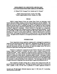
The prototype consists of ve blocks containing 512 straws each. Each block, as seen in g. 1, contains 16 layers of radial straws interleaved with radiator stacks, made of 17 polypropylene foils of 15 �m thickness and spaced on average by 265 �m. Each layer contains 32 straws positioned in a support frame with an accuracy of 100 �m. The total length of the detector is 780 mm. The support frames are staggered with respect to one another, in such a way as to minimise the uctuations in the total number of straws crossed by beam particles as a function of their impact point on the prototype. The edges of the frames provide a common gas manifold for all the straws and the necessary electrical connections. One distributed blocking capacitance of 800 pF is connected to each group of 16 straws. No cross-talk was observed within the accuracy of the measurements, which was better than 1%. The inner part of the frames is constructed out of carbon bre reinforced plastics, to minimise the amount of material. As a result, the average thickness of this inner support, including the straw xations and end-plugs, is about 1.4% X0 for particles crossing at normal incidence. The straws have an inner diameter of 4 mm and have 60 �m thick walls made of coated polyimide lm [6, 7]. The straws are reinforced with carbon bres to increase the rigidity and to prevent the straws from creeping under variations of humidity and temperature. Their length was chosen to be 33 cm, due to the limited amount of space available inside the solenoidal magnet used for the 1995 measurements with the prototype. The front-end electronic chips are connected to printed-circuit boards situated at the outer radius of the frames. The active gas in the straws consisted normally of 70% Xe, 20% CF4 and 10% CO2 . By examining the gas-gain uniformity of all 2560 straws, it was found that 97% of the straws have a wire o�set below 300 �m, which guarantees stable operation under LHC conditions. All straws have been operating under high voltage in a reliable way over several years. The sector prototype was operated with a gas 1
Figure 1: One of the ve blocks in the TRT prototype before the electronics boards were mounted. The outermost layer of radially mounted straws can be seen.
ow of 0.05 cm3 =min per straw, which corresponds to about one volume per hour.
3
Front-end electronics and readout
In addition to the stringent requirement to operate up to straw counting rates of 20 MHz at the LHC design luminosity, the nal electronics of the TRT should ful l requirements common to all types of LHC readout electronics: { Radiation hardness. { Low power consumption. { Operation at a 40 MHz bunch crossing (BX) rate. { Storage of data on detector for around 3 �s. { Continuous readout at a rate of up to 75 kHz. { Readout through high bandwidth links. { Readout format compatible with level-2 trigger requirements. As explained in detail below, many of these requirements were already implemented for the development version of the electronics on the prototype. The most signi cant di�erence is that the readout chips were not manufactured in a radiation-hard process. The long ion tail observed in the straw signal, characteristic of xenon gases, requires an accurate tail cancellation circuitry to avoid baseline shifts at counting rates of up to 20 MHz. A detailed analysis of the properties of the straw signal can be found in [8]. Minimum-ionising particles produce extended ionisation with an average energy around 2 keV. On the other hand, transition radiation photons, which are generated by electrons crossing the radiator foils between the straw layers, deliver a point-like ionisation with an energy several times higher than the ionisation from the particle itself. Both types of signals can be recorded by means of a fast preampli er/shaper circuit combined with two discriminators, one with a low threshold ( 0:2 keV), which e�ciently registers signals from primary ionisation, and one with a high threshold ( 6 keV), which registers a large fraction of the absorbed TR photons. �
�
3.1 System overview
A simpli ed functional block diagram illustrating the readout sequence for one straw is shown in g. 2. The signal from the straw is processed in the preampli er/shaper circuit. The output signal is compared in two discriminators with low and high threshold as described above, and the resulting two bits are latched and stored in the digital pipeline at the rising edge of the bunch crossing (BX) clock. If the low-threshold discriminator red, a 3-bit Gray-encoded timing value is latched and stored in the pipeline. The three bits describe the time between the previous rising edge of the BX clock and the arrival of the signal, i.e. the drift time in the straw. The pipeline stores ve bits of information for each time slice of 25 ns over a period of around 3 �s (128 clock cycles). 2
Upon an accept signal from the level-1 trigger, the trigger decision logic selects the three relevant consecutive time slices and stores their information into a derandomiser (readout bu�er). The data in the derandomiser are kept until an output-enable signal is issued by the back-end electronics. The back-end unit reads out, packs and sends to the DAQ system the data from 512 channels. The back-end unit is also responsible for the slow control of the front-end circuits and the level-1 trigger management. STRAW DETECTOR
PREAMPLIFIER
High thr.
Low thr.
SHAPER BX 2 DISCRIMINATORS DRIFT TIME MEASUREMENTS
DTM
DIGITAL PIPLINE
ON detector
(128 CELLS)
SELECT
DERANDOMISER
Read EVENT
DATA SELECTOR
BUFFER 5 EVENTS SHORT LINK
2.5 m OFF detector
Trigger LEVEL 1
LOCAL
LOGIC
(ROD, PHI slice builder)
READOUT CONTROL TRIGGER HANDLING EVENT BUILDER DATA TRANSMIT
25 m HIPPI VME
DAQ
Figure 2: Complete chain of front-end electronics and readout system from the straws to the VME module readout by the DAQ. The details for one readout channel are explicitly shown.
3.2 Transition Radiation Detector Analog (TRDA) integrated circuit
This 8-channel integrated circuit [9, 10] corresponds to the preampli er/shaper and discriminator stages shown in g. 2. It contains a common-base bipolar input stage with charge integration at the collector. The shaper contains four integrators and two pole/zero cancellation stages. The output analog signal has 12.5 ns peaking time and a 15 ns falling time. The equivalent noise charge is at the level of 2000 electrons for a 10 pF input capacitance. The preampli er/shaper is followed by two Schmitt triggers (comparators with hysteresis), which guarantee a minimal output pulse width of 5 ns. In order to avoid high-swing signals close to the sensitive inputs, a di�erential low-amplitude current-sensitive interface was chosen. The information from the low and high-threshold comparators is ternary encoded in order to save output pins. This ternary interface encodes the values of the low and high-threshold outputs, according to table 1, which shows that the total value of the current in both pins of the ternary interface is constant. State True Complement current current No signal 1 3 Low threshold only 2 2 Low and high threshold 3 1
Table 1: Ternary interface state assignment for the TRDA chip. The currents are given in units of 200 �A. The TRDA is an 8-channel chip produced in the PLESSEY bipolar process. It is packaged in a 44pin PLCC package and its power consumption is 12.5 mW/channel. During the testing of the prototype, TRDA chips ceased operating at a slow rate, resulting in a loss of about 20% of the chips at the end of the testbeam period in 1996. Examination of the dead chips showed that a short track between an input bond pad and its protection diode had been vaporised by high-energy electrical discharges. Test inputs veri ed that the following circuitry was still operational. A low-value external resistor would have prevented this problem but was omitted to save space. Such a resistor is implemented for the successor [11] of the TRDA. 3
3.3 Transition Radiation Detector Service (TRDS) integrated circuit
This 8-channel chip [12] receives the ternary signals from one TRDA chip and decodes and converts them to standard CMOS signals. It contains two 5-bit DACs to set the low and high thresholds for the TRDA discriminators. For the standard gas gain, the low threshold can be varied from around 0 to 1 keV and the high threshold from 0 to 9 keV. The scales are linear and can be varied in steps of 1/32 of the maximum setting. There is a possibility to mask bad channels in the TRDS and to generate test pulses which are injected to the TRDA inputs. The test-pulse amplitude is adjustable with a 3-bit resolution. Test pulses can be generated separately for even and odd channels. The TRDS was produced in the ESS 2 �m CMOS process and packaged in a 68-pin PLCC package. It has a power consumption of 7.5 mW/channel.
3.4 Drift-Time Measuring ReadOut Chip (DTMROC)
The 32-channel DTMROC [13] receives low and high-threshold signals from four TRDS chips. These signals, which can be as short as 5 ns, are latched synchronously with the BX clock. The chip also measures the drift time using a Delay Locked Loop (DLL). The DLL supplies a 3-bit Gray-encoded word, which represents the time elapsed since the previous rising edge of the BX clock. The contribution p of the DTMROC to the Gaussian resolution of the drift-time measurement is thus 0.90 ns ( 225ns 3 12 ), contributing a constant term of about 50 �m to the overall drift-time accuracy. The data from the low and high-threshold discriminators and the drift-time measurement (5 bits/straw and clock cycle) are written to a digital pipeline. The pipeline is 128 BX clock cycles long, allowing for a total level-1 trigger latency of 3.2 �s. The level-1 trigger signal activates internal circuitry and the data from three time slices, corresponding to the tagged event, are transferred from the pipeline to a so-called derandomiser. The derandomiser can store up to ve events. The readout of the data output is organised on three serial outputs running at 20 MHz, and is activated when the Output Enable signal is transmitted from the back-end electronics. The DTMROC was produced in the AMS 1.0 �m CMOS process and packaged in a 84-pin PLCC package with a power consumption of 7 mW/channel.
3.5 Front-end boards
The basic readout unit for the prototype is formed from four TRDA chips, four TRDS chips and one DTMROC placed on one front-end board, as shown in g. 3. The analog TRDA integrated circuits are placed on one side of the readout board, while the digital TRDA and DTMROC chips are placed on the other side. In this way, the sensitive analog input lines from the straws are protected as much as possible from the digital transmission lines. The front-end boards are placed directly on the detector prototype and serve 32 straws. Eight front-end boards form a group which is connected to one so-called roof board. The roof board distributes power and services to front-end boards and collects the readout lines.
Figure 3: A front-end board from the TRT prototype. The 32-channel DTMROC is visible on top with four 8-channel TRDS chips below. The four TRDA chips are on the other side of the board. A total of 32 straws can be connected to the pins at the bottom of the picture and the connector on top ts into a roof board. 4
3.6 Back-end electronics
The data from two roof boards, corresponding to 16 front-end boards or 512 straws, are collected on a so-called Local Logic board, which controls the readout protocol. The state of the derandomiser and the available bu�er space are checked by the trigger logic which provides a BUSY signal to the central trigger logic before the derandomiser in the DTMROC or the bu�ers on the Local Logic boards become full. A DAQ system developed at CERN was used [14]. In addition to the standard DAQ modules, those speci c to the TRT prototype were: { A Trigger Delay Module (TDM), which receives signals from the external trigger logic and synchronises them with an on-board generated 40 MHz clock to emulate the LHC clock cycle in the SPS conditions. The phase between the external trigger and the clock is measured with a 4-bit precision (1.6 ns per bin) and transmitted to the Local Logic together with the level-1 trigger signal. This provides a measurement of the o�set in time between the beam particle and the rising edge of the 40 MHz clock on an event by event basis. The trigger is delayed to match the front-end pipeline length and delivered together with the clock signal to the front-end boards. { A Slow Control Module (SCM), which mediates all slow control and parameter loading as well as the Local Logic programming and initialisation.
4
Testbeam setup
The sector prototype described above was tested in the H8 beam line at the CERN SPS during several periods in 1995 and 1996. The beam line was equipped with a precise beam telescope, consisting of three silicon microstrip detectors, two standard beam chambers, a Cherenkov counter, and a preshower detector together with a small electromagnetic calorimeter (lead-glass array or RD3 prototypes of the ATLAS liquid argon electromagnetic calorimeter [15]). With this detector con guration, an electron/pion separation at the level of 10 5 was achieved when necessary, and beam-particle tracks could be extrapolated to the sector prototype with an accuracy of 10 �m. The total amount of material in front of the detector was approximately 11% of a radiation length. Silicon detectors
Magnet
Preshower B
Beam
1938
Beam chambers
790
Calorimeter
TRT sector prototype
Figure 4: Top view of the TRT prototype setup in the 1995 testbeam run. The solenoidal magnet containing the prototype was rotated by 19� with respect to the beam line. All distances are in mm. In the 1995 testbeam run, the detector was placed in a small solenoidal magnet with a maximum eld of 0.8 T. The magnet was, as seen in g. 4, rotated by 19� with respect to the beam line to achieve maximum bending of the beam particles. The sector prototype was thus placed in a con guration similar to that at a pseudorapidity � = 1:8 at the LHC. In the 1996 testbeam run, the beam line was equipped with a large superconducting dipole magnet, with which testbeam measurements of the sector prototype were carried out in a magnetic eld of up to 1.56 T. The layout of the testbeam setup and some of the most important geometric parameters are shown in g. 5. In this setup, the straws are almost parallel to the magnetic eld, corresponding to the layout foreseen in ATLAS at a pseudorapidity � 0. The setups described above have been used extensively to evaluate the TRT sector prototype performance, using beams of electrons and pions with energies of 20 to 200 GeV, with and without magnetic eld, and also using tagged photon beams, where the trigger forced the photon to convert in front of or inside the prototype. �
5
Track reconstruction
For the studies of pion rejection, a simpli ed tracking algorithm which did not make use of the drift-time information from the straws was used. A straw has a (low-threshold) hit if the low-threshold 5
Profile of magnetic field 1.56 T
Beam chambers Silicon detectors
Si3
4000
Preshower
Magnet B
Beam
939
2118
TRT sector prototype
790
Calorimeter
200
Magnet
TRT sector prototype
Figure 5: Side view (left) and transverse view (right) of the TRT prototype setup in the 1996 testbeam run at the H8 beam line of the CERN SPS. All distances are in mm. The sector prototype inside the dipole magnet is enlarged to improve visibility. discriminator red at any time during the three time slices read out for an event. For single particles crossing the detector, the simpler track reconstruction algorithm, using no drift-time information from the straws, provides a comparable rejection power to that obtained with an optimal tracking algorithm. Tracking studies using the drift-time information are presented in [16]. The alignment of the straws was done by extrapolating the tracks reconstructed using the silicon telescope to each layer of straws. For all straws with a hit in the layer, the position of the extrapolated track contributed to a straw pro le. After normalising the pro le of each straw to the pro le of the beam, the position of the 4 mm wide and nearly square pro le was tted with a function of the type (1) f (x) = A e 21 ( � 0 ) ; where x0 is the position of the tted straw centre, A is the straw e�ciency, and the half-width � of the x x
8
pro le has a value of 2 mm. The alignment correction for a straw was determined as the di�erence between the position calculated from the geometry of the TRT prototype and the centre x0 of the tted straw pro le. Normalised hit frequency
Normalised hit frequency
'
0 µm
1
0.8
0.6
0.8
0.6
0.4
0.4
0.2
0.2
0
0
0.5
1
1.5
2
2.5
3
Distance from track (mm)
150 µm
1
0
0
0.5
1
1.5
2
2.5
3
Distance from track (mm)
Figure 6: Distance from the track reconstructed with the beam telescope to all the hit straws in the detector, for data (points with error bars) and Monte Carlo (shaded histogram). The two gures correspond to a perfect straw alignment in the Monte Carlo (left) and to a 150 �m Gaussian spread applied to the positions of the straws inside each layer (right). Due to the narrow pro le of the beam (1 cm), only one alignment correction could be determined with su�cient statistics for each layer of 16 straws. Therefore, straws which were at the edge of the beam and thus impossible to align properly, were given the same alignment correction as the straw in the same layer placed fully inside the beam. 6
Using the aligned positions of the straws, the distance from the centre of hit straws to the extrapolation of the track reconstructed with the beam telescope was then calculated. This calculated distance, plotted for all hits in the detector and for many events, is shown in g. 6. Distances above 2 mm correspond to hits coming mainly from �-rays emitted by the beam particle. Comparisons were made to the Monte Carlo with a Gaussian spread applied to the positions of the straws inside each layer. The results for a 0 �m spread (perfect straw alignment) and for a 150 �m spread are shown in g. 6. The best t to the data is obtained for a spread of 150 �m, which consists of a 100 �m contribution from construction and of a 100 �m contribution from residual non-straightness of the straws. A parabolic t accounting for the e�ect of the magnetic eld was made to the hits found by the tracking algorithm, and only reconstructed tracks with parameters matching the direction and momentum of the beam particles were selected for further analysis. The track parameters from the beam telescope were not used in the track t. The number of hits along the reconstructed track, before and after matching to the beam parameters, is shown in g. 7. �
Relative fraction of tracks
�
-1
10
-2
10
-3
10
0
5
10
15
20
25
30
35
40
45
50
Number of hits along track
Figure 7: Number of hits on the reconstructed tracks in the TRT prototype before (open) and after (shaded) matching to the beam parameters (magnetic eld of 0.8 T).
6
Electron identi cation
All results reported here were obtained with beams of 20 GeV pions and electrons. As discussed in section 1, electron identi cation using transition radiation makes use of the di�erence in the energy deposited in the straws by electrons and by charged pions, which are the main background source to electrons at the LHC. For electrons, the tail above 5{7 keV is dominated by transition radiation hits, while for pions it is mostly due to �-rays. The pion rejection is calculated by counting the number of high-threshold hits on reconstructed tracks for pions and electrons (see g. 8). The distribution of high-threshold hits on the reconstructed tracks is expected to follow a binomial law. This is illustrated in g. 9, where a t has been performed to the pion and electron data of g. 8. The distributions follow the binomial law over several orders of magnitude and do not display any poorly understood tails. By requiring more than a certain number of high threshold hits along the track, the e�ciency for misidentifying pions as electrons is measured as a function of the electron e�ciency. For data taken in a 0.8 T eld with a high-threshold discriminator setting of 6 keV, g. 10 shows the result of applying this procedure to the distributions of g. 8. For an electron e�ciency of 90%, the measured pion e�ciency is around 1.2% or, correspondingly, the measured rejection against pions is a factor of 80. The high-threshold setting for the TRDA chip can be varied and the pion rejection depends to some extent on the value chosen. The discriminator threshold was calibrated to a 5% accuracy, using data taken with a 5.9 keV 55 Fe X-ray source. For a xed electron e�ciency of 90%, g. 11 shows the measured pion e�ciency as a function of the setting of the high-threshold discriminator. The electron identi cation performance is seen to be quite stable for thresholds between 5 and 7 keV. Further results reported in this paper for pion e�ciencies are given for a threshold of 6 keV and an electron e�ciency of 90%. 7
Relative fraction of tracks
Relative fraction of tracks
0.3
Pions
0.25
0.2
Electrons
0.15
1
Pions -1
Electrons
10
-2
10
0.1 -3
10 0.05 -4
0
0
5
10
15
20
25
30
Number of high threshold hits
Figure 8: Distribution of the number of high-threshold hits (above 6 keV) on reconstructed tracks from 20 GeV pions and electrons in a magnetic eld of 0.8 T.
7
10
0
5
10
15
20
25
30
Number of high threshold hits
Figure 9: Distribution of the number of high-threshold hits for pions and electrons in a magnetic eld of 0.8 T. The points with error bars represent the data and the histograms a t of the data to a binomial distribution.
Monte Carlo model of the TRT prototype
A detailed Monte Carlo, using geant 3.21 [17], has been developed to simulate the TRT prototype and the complete beam line. It makes use of the same software modules as the simulation of the TRT in the ATLAS Inner Detector, thus providing as accurate as possible a calibration for the performance studies of the nal detector. While the TRT prototype and the silicon telescope are simulated in detail, the other parts of the beam line are only included as passive material. The material included in the simulation matches the amount and distribution in the beam line to an accuracy much better than the 10% uncertainty in the actual amount of material present.
7.1 Simulation of the straw signal
The simulation of the electron identi cation performance of the TRT requires an accurate description of: { The straw response to the energy deposited by minimum ionising particles. { The production and absorption of transition radiation photons. The energy depositions considered here are in the range from the ionisation potential, i.e. 10 eV, to 20 keV, which is not adequately simulated by geant 3.21. In addition, geant does not contain transition radiation as a physical process. For these reasons, a detailed Monte Carlo model has been developed. It describes all the relevant features of energy depositions in the straws, of transition radiation creation and absorption, and of the response of the associated electronics. This Monte Carlo model reproduces in particular quite accurately the measured position resolution and e�ciency of the straw as a function of its counting rate [18]. The next sections of this paper describe in some detail how well the measured probabilities to observe hits above the high threshold for electrons and pions are reproduced by this Monte Carlo model. The simulation of the straw response consists of the following steps: { The ionisation deposited by each charged particle crossing a straw is calculated from its Lorentz factor , using the Photo-Absorption Ionisation Model (PAI Model) [19, 20]. This energy is divided among a small number of primary ionisation centres (on average, 18 at normal incidence). The energy and spatial uctuations of dE=dx measured in straws are well reproduced by the Monte Carlo using the PAI model. { The energy associated with any absorbed transition radiation photons is added to the energy deposited in the gas. { The signal amplitudes and arrival times on the wire are summed over all primary clusters for all charged particles crossing the straw. This sum forms the time-dependent straw output signal. �
�
8
Pion efficiency (%)
Pion efficiency
1
-1
10
-2
10
5 4.5 4 3.5 3 2.5 2 1.5
-3
10 1 0.5 -4
10
0.5 0.55 0.6 0.65 0.7 0.75 0.8 0.85 0.9 0.95
1
0
4
4.5
5
Electron efficiency
Figure 10: Pion versus electron e�ciency, obtained by varying the number of high-threshold hits required on reconstructed tracks.
5.5
6
6.5
7
7.5
8
8.5
9
Threshold (keV)
Figure 11: Pion e�ciency as a function of the discriminator threshold, for a xed electron e�ciency of 90% and for 20 GeV pions and electrons in a 0.8 T magnetic eld.
{ The amplitude of the time-dependent straw output signal is reduced to account for space-charge
e�ects, using the results from measurements performed as a function of the deposited energy and the gas gain [21]. { The straw output signal is convoluted with a model of the electronics signal shape, based on measurements of the response of the TRDA chip. A distribution of the pulse-height as a function of time is thus generated for each straw. { A low (minimum-ionising) and a high (transition radiation) threshold are then applied to the resulting signal, which can fail to cross the threshold, cross the threshold once, or cross the threshold more than once. Both thresholds can be adjusted to match the threshold settings on the TRDA chip. { The discriminator response is modelled with a pulse-width equal to the time over threshold plus 2 ns (but not shorter than 10 ns) and with a recovery time of 5 ns after the pulse drops below threshold. { The distance of the charged particle to the wire is reconstructed, using the time of the leading edge of the low-threshold discriminator output and the established time-to-distance relationship as described in [8]. { The drift-time accuracy for a single straw is predicted to be typically 140 �m for a peaking time of 12.5 ns, in good agreement with testbeam data. In the simulation, transition radiation photons are generated in the radiator material for charged particles with a Lorentz factor above 1000. The energy spectrum of emitted transition radiation photons is simulated following the formulae of [1, 22] for regular foils. The energy spectrum is then transported along the particle track (an approximation which is accurate enough in the ATLAS TRT for electron transverse momenta above 1 GeV), partially absorbed in the radiator and the straw walls, and partially absorbed in the xenon gas mixture inside the straws. The predicted energy spectrum of the absorbed transition radiation has been shown to be in reasonable agreement with testbeam data [3].
7.2 Calibration of the Monte Carlo model
The probability per straw to observe a high-threshold hit on the reconstructed track as a function of the threshold in keV is shown in g. 12 for pions and electrons in a 1.56 T magnetic eld. The testbeam measurements are represented as horizontal bands with a width corresponding to the measurement errors. As discussed in section 6, the energy scale of the high-threshold discriminator was nominally set to a value of 6 keV and calibrated to a 5% accuracy. For pions, the high-threshold hit probability is measured to be 4:93 0:07%, which corresponds to a value of 6:00 0:06 keV for the high threshold, in excellent agreement with the 55 Fe measurements mentioned in section 6. Once this scale is xed, the simulation can be compared to the data from electrons which produce transition radiation. The Monte Carlo model used for the production of transition radiation is valid for an ideal radiator with perfectly regular foil spacings and foil thicknesses. In reality, the �
�
9
prototype radiator geometry is not perfectly regular, and a tunable overall reduction factor was applied to the amount of transition radiation produced. This factor re ects the relative radiator performance with respect to an ideal radiator, and was found to be 88:4 2:2 2:0% for a 6 keV threshold, as shown in g. 12. The rst quoted error is statistical and the second one is an estimate of the systematic error, based on the analysis of data taken at di�erent periods during the testbeam run in 1996. This measured relative radiator performance was found to be stable as a function of the choice of geant cuto�s used in the Monte Carlo model. �
Pion efficiency (%)
Fraction over threshold
0.35
MC elec (80%) MC elec (90%) MC pion
0.3
0.25
�
Electron data
0.2
6
MC (80%) MC (90%) Data
5
4
3
0.15 2
0.1
Pion data
0.05 0
2.5
3
3.5
1
4
4.5
5
5.5
6
6.5
7
0
7.5
3
3.5
4
4.5
Threshold (keV)
5
5.5
6
6.5
7
7.5
Threshold (keV)
Figure 12: Probability to observe a highthreshold hit in a straw crossed by a pion or electron track as a function of the value chosen for the high threshold. The results are shown as horizontal bands for the data, which were taken at a xed threshold of approximately 6 keV, and as curves for the Monte Carlo simulations. For the simulation of electrons, the results are shown for relative radiator performances of 80% and 90% (see text).
Figure 13: Pion e�ciency at a xed electron e�ciency of 90% as a function of the high threshold. Results from measurements in a 1.56 T magnetic eld are compared with Monte Carlo predictions for relative radiator performances of 80% and 90%.
The measured and predicted pion e�ciencies at a xed electron e�ciency of 90% are shown in g. 13 as a function of the high threshold. Data taken in a 1.56 T magnetic eld are compared to simulations with relative radiator performances of 80% and 90%. This gure shows that the relative radiator performance varies from 80% for a threshold around 4.5 keV to 90% for a threshold above 6 keV. The shape of the transition radiation spectrum is therefore not reproduced accurately enough by the simulation. More detailed comparisons between measured and predicted transition radiation spectra and spectra can be found in [23]. �
�
8 Dependence of the electron identi cation on detector parameters 8.1 E�ect of the detector length
The pion e�ciency depends strongly on the total length of the detector, as illustrated in g. 14, which shows the pion e�ciency as a function of the length of the TRT prototype used in the measurement. The electron/pion separation improves approximately by a factor of two for each additional 150 mm of detector length. If the readout electronics in a given layer of the prototype have ceased to operate, this layer cannot provide any additional pion rejection. In g. 14, this e�ect can be seen for straw layers situated at a length of around 680 mm, where the rejection power does not improve over a succession of three consecutive layers. All results, presented in this paper for data taken with one or more non-functional layers, have been corrected, using the exponential dependence of the pion e�ciency as a function of the detector length. 10
Pion efficiency (%)
Pion efficiency
-1
10
Data MC
1.4 1.2 1 0.8 0.6 0.4
-2
10
0.2
200
300
400
500
600
0
700
Active detector length (mm)
0
0.2
0.4
0.6
0.8
1
1.2
1.4
1.6
Magnetic field (T)
Figure 14: Pion e�ciency at a xed electron e�ciency of 90% as a function of the length of the prototype used for the measurement. The error bars are strongly correlated from point to point.
Figure 15: Pion e�ciency at a xed electron e�ciency of 90% as a function of the magnetic eld (parallel to the straws).
8.2 E�ect of the magnetic eld
A good understanding of the behaviour of the TRT prototype in a high magnetic eld is of importance, since the ATLAS TRT will operate in a eld of 1{2 T. In the 1996 setup, it was possible to measure the performance up to a maximum eld of 1.56 T. For four di�erent values of this magnetic eld, the pion e�ciency was evaluated at a xed electron e�ciency of 90%, as shown in g. 15. The di�erence between the data and the simulation is less than the variations caused by the systematic uncertainty on the determination of the relative radiator performance. For 20 GeV beams of pions and electrons, no signi cant change of the performance as a function of the magnetic eld was observed.
8.3 E�ect of variable straw density
In the case of the 1996 setup, where the beam was perpendicular to the straws, it was possible to measure the impact of the straw density per layer on the electron identi cation performance. This was done by moving the prototype by 6 cm and 12 cm in the vertical direction, as shown in g. 16. �
�
Outer support
Beam positions
Straws
Inner support
Figure 16: Schematic view of a single straw layer with the di�erent positions of the beam used to measure the impact of the straw density per layer on the electron identi cation performance. The relative radiator performance was determined for each position of the prototype, as described in section 7.2, and the results including their statistical errors are shown in g. 17. As the distance between straws increases from 6 mm to 10 mm, the relative radiator performance decreases from 95% to 84%. This decrease is signi cant, since the probability, that the measured relative radiator performance is constant 11
Pion efficiency (%)
Relative performance (%)
and therefore that the measurements shown in g. 17 are only statistical uctuations, is below 10 3. Since the pion measurements are not a�ected by variations in the straw density, the only possible source for this e�ect is, once again, the simulation of the absorbed transition radiation spectrum. The formula of [22] for transition radiation production in the case of radiator foils with irregular spacing was also implemented in the simulation, to investigate whether the di�erences between data and simulation discussed above could be caused by the simpli ed simulation using regular radiator foils (see section 7.2). The absorbed transition radiation spectrum predicted by the more detailed simulation was found to be very similar to that predicted by the simpli ed approach, thus providing no further explanation.
100
95
90
2.5
B=1.56 T (data) B=1.56 T (MC)
2
1.5
1
85
0.5
80
6
7
8
9
10
Distance between straws (mm)
Figure 17: Measured relative radiator performance in a 1.56 T magnetic eld as a function of the straw density. The straw density is expressed as the distance between adjacent straws at the position of the beam.
0
6.5
7
7.5
8
8.5
9
9.5
10
10.5
Distance between straws (mm)
Figure 18: Measured and predicted pion e�ciency at a xed electron e�ciency of 90% as a function of the straw density in a 1.56 T magnetic eld. The simulation results are shown for a relative radiator performance of 88.4% (see text).
The dependence of the pion e�ciency on the straw density in a 1.56 T magnetic eld is shown in g. 18 for a xed electron e�ciency of 90%. The measurements are compared to the predictions for a relative radiator performance of 88.4%. This value corresponds to the performance measured for the central position of the prototype, i.e. to a distance between straws of 8.5 mm, and was found to be too low for higher straw densities and too high for lower straw densities (see g. 17). The predicted pion e�ciency therefore varies much less with the straw density than the measured one.
8.4 E�ect of the gas parameters
The parameters of the gas obviously also a�ect the electron identi cation performance. The tracking performance of the detector can be improved by lowering the xenon concentration and thereby increasing the drift velocity, or by increasing the gas gain above the nominal value of 2:5 104 . Data without magnetic eld were taken with two gas mixtures: the standard 70% Xe, 20% CF4 , 10% CO2 mixture and a mixture with 40% Xe, 50% CF4 , 10% CO2 . For a high threshold of 6 keV, the pion e�ciency increases by a factor of 8, from 1.2% with 70% Xe to 9.6% with 40% Xe. This large degradation of the electron identi cation performance, due to the signi cant loss of X-ray absorption in the straw gas, is in good agreement with earlier results, using xenon concentrations between 50% and 70% [5]. The electron identi cation performance is also signi cantly degraded if the gas gain increases substantially, as shown in g. 19. Space-charge e�ects around the wire reduce the e�ective gas gain substantially for energy depositions above 5 keV, and are enhanced as the gas gain increases [21]. �
9
Conclusions
A prototype of the Transition Radiation Tracker (TRT) of the ATLAS detector has been built. The geometry and materials of this prototype and the characteristics of its readout electronics are close to those foreseen for the operation of the TRT detector at the LHC. The prototype has been tested over a wide range of operating conditions and has shown reliable and stable performance. Results on the electron identi cation performance have been presented in this 12
Normalised pion efficiency
Data MC 2.5
2
1.5
1
0.5
0
2.4
2.6
2.8
3
3.2
3.4
3.6
3.8
4
4.2 4
Gas gain (×10 )
Figure 19: Measured and predicted pion e�ciency at a xed electron e�ciency of 90% as a function of the straw gas gain. Both the measured (black squares) and predicted (open circles) values are normalised to the pion e�ciency at the nominal gas gain of 2:5 104. �
article and show that, for an electron e�ciency of 90%, a pion e�ciency of 1% can be achieved over a detector length of 780 mm. The performance was measured to be stable as a function of the discriminator threshold (from 5 to 7 keV) and of the magnetic eld (from 0 to 1.6 T). In contrast, the performance was found to be quite sensitive to the choice of gas gain and to the amount of xenon gas in the straws. Although detailed Monte Carlo simulations have been shown to accurately describe the measured straw performance in terms of drift-time measurement accuracy and e�ciency, the simulation of the transition radiation cannot predict the measured electron identi cation performance without introducing normalisation factors, which presumedly re ect the limited knowledge of the exact geometry of the foil radiator and also of the exact energy spectrum of produced and absorbed X-ray photons. On average, the measured radiator performance was found to be almost 90% of that expected from a perfectly regular radiator. The above results can be used to evaluate more quantitatively the expected electron identi cation performance of the TRT at the LHC, as described in detail in [3]. The expected pion e�ciency, at a xed electron e�ciency of 90%, varies from 0.5% to 8% (resp. 1.6% to 16%) over the di�erent regions of the TRT detector, at a luminosity of 1033 cm 2 s 1 (resp. 1034 cm 2 s 1 ). �
Acknowledgement
We thank K. Bussmann, T. Nilsson and G. Di Tore for their contributions to the preparation of mechanics and electronics in the testbeam. We also thank the RD13 collaboration for the use of their Data Acquisition System and the RD3 collaboration for the use of a prototype of the ATLAS liquid argon calorimeter. The research described in this article was partly made possible thanks to Polish State Grant No KBN 2P03B00212, the Swedish Natural Science Research Council, the Swedish Council for Planning and Coordination of Research, the United States Department of Energy under award number DEFG0291ER-40661 and the UK Particle Physics and Astronomy Research Council.
References
[1] M. Cherry, G. Hartmann, D. Muller, and T. A. Prince. Transition radiation from relativistic electrons in periodic radiators. Phys. Rev., 10:3594{3607, 1974. [2] X. Artru, G.B. Yodh, and G. Mennessier. Practical theory of the multilayered transition radiation detector. Phys. Rev., D12(5):1289{1306, 1975. [3] ATLAS Collaboration. ATLAS Inner Detector Technical Design Report volume 1. CERN/LHCC/9716, 1997. [4] J. T. Shank et al. Test beam performance of a tracking TRD prototype. Nucl. Instrum. Meth., A309:377{385, 1991. 13
[5] T. Akesson et al. Particle identi cation performance of a straw transition radiation tracker prototype. Nucl. Instrum. Meth., A372:70{84, 1996. [6] V. Bondarenko et al. Kapton straw chambers for a tracking transition radiation detector. Nucl. Instrum. Meth., A327:386{392, 1993. [7] T. Akesson et al. Study of straw proportional tubes for a transition radiation detector / tracker at LHC. Nucl. Instrum. Meth., A361:440{456, 1995. [8] T. Akesson et al. The ATLAS TRT straw proportional tubes: Performance at very high counting rate. Nucl. Instrum. Meth., A367:143{153, 1995. [9] M. Millmore. RAL internal note, RAL-118, 1992. [10] D. White. RAL internal note, RAL-161, 1994. [11] B. Bevensee et al. An ampli er-shaper-discriminator for the ATLAS Transition Radiation Tracker. IEEE Trans. Nucl. Sci., 43:1725{1731, 1996. [12] J. Dowdell. RAL internal note, RAL-117, 1992. [13] H. Carling and M. Thulesius. Technical Speci cation of the RD6 Drift Time Measuring ReadOut Chip, Revision 3. Lund University internal report, LUNFD6(NFFL-7097), 1995. [14] S. Buono et al. Software engineering techniques and CASE tools in RD13. Nucl. Instrum. Meth., A352:383, 1994. [15] D. M. Gingrich et al. Performance of a large scale prototype of the ATLAS accordion electromagnetic calorimeter. Nucl. Instrum. Meth., A364:290{306, 1995. [16] T. Akesson et al. Tracking with a prototype of the Transition Radiation Tracker for the ATLAS experiment. To be published. [17] CN division Application Software group. GEANT Detector Description and Simulation Tool. CERN Program Library Long Writeup W5013, 1993. [18] T. Akesson et al. Straw tube drift time properties and electronics parameters for the ATLAS TRT detector. To be published. [19] W. W. M. Allison and J. Cobb. Relativistic charged particle identi cation by energy loss. Ann. Rev. Nucl. Part. Sci., 30:253, 1980. [20] V. M. Grishin, V. K. Ermilova, and S. K. Kotelnikov. Fast particle identi cation based on the relativistic increase of the threshold e�ciency in multilayer proportional detectors. Nucl. Instrum. Meth., A307:273, 1991. [21] ATLAS Collaboration. ATLAS Inner Detector Technical Design Report volume 2. CERN/LHCC/9717, 1997. [22] G. M. Garibian, L. A. Gevorgian, and C. Yang. The calculation of X-ray transition radiation generated in regular- and irregular-layered media. Nucl. Instrum. Meth., 125:133, 1975. [23] W. Funk. A systematic study of the particle identi cation performance in the Transition Radiation Tracker (TRT) of ATLAS. ATLAS Internal Note INDET-No-157, 1997.
14